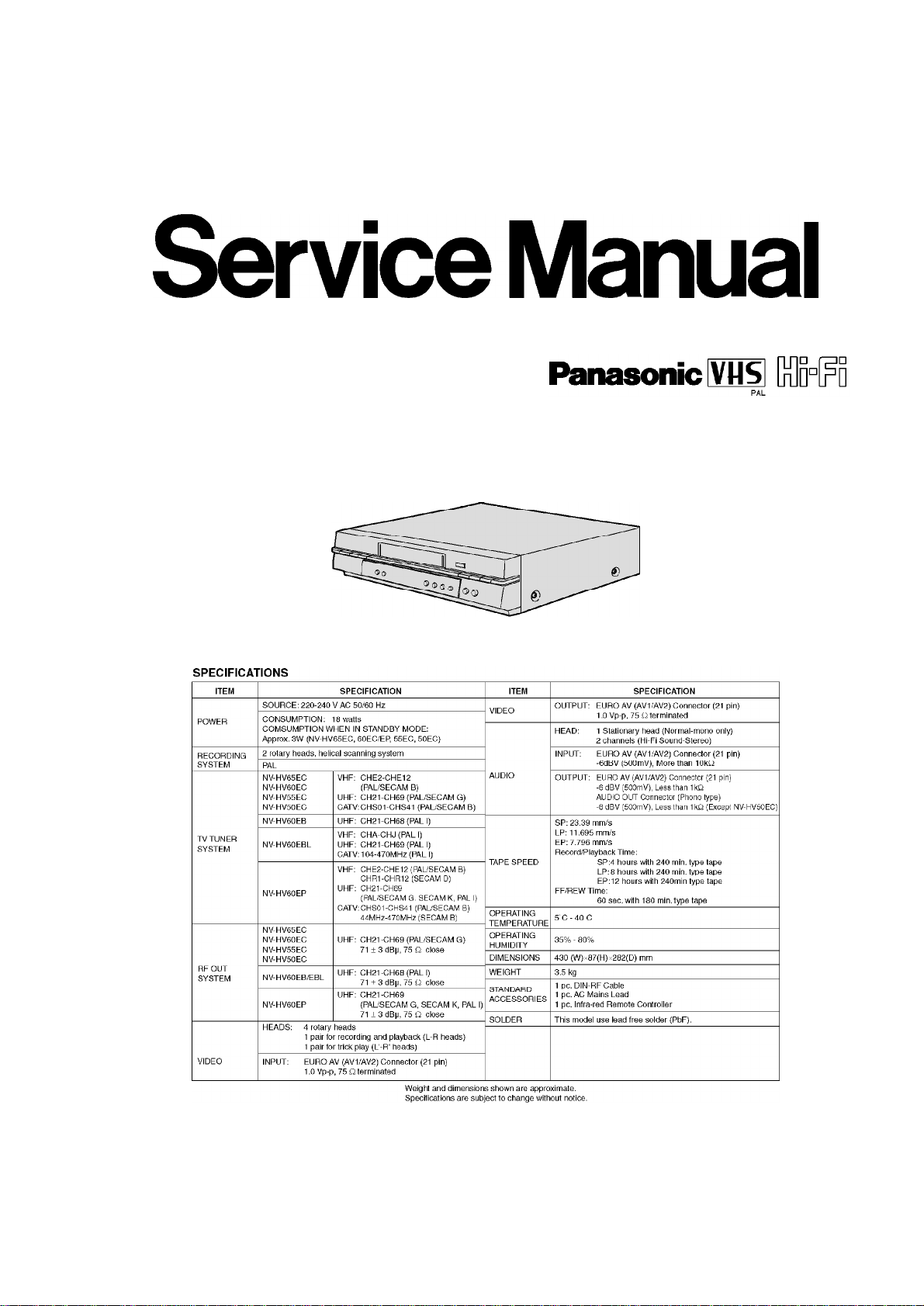
Panasonic NV-HV65EC User manual
Other Panasonic VCR System manuals

Panasonic
Panasonic NV-SJ230A User manual

Panasonic
Panasonic Series Hi-Fi NV-HV61 User manual

Panasonic
Panasonic OmniVision PV-M1339 User manual

Panasonic
Panasonic Omnivision PV-V4601 User manual

Panasonic
Panasonic ProLine AG-1340P User manual

Panasonic
Panasonic OmniVision PV-QV200 User manual

Panasonic
Panasonic NV-SD450EU User manual

Panasonic
Panasonic Omnivision PV-V4530S User manual

Panasonic
Panasonic NV-FJ631EG User manual

Panasonic
Panasonic ProLine AG-1320 User manual

Panasonic
Panasonic NV-SD430 Series User manual

Panasonic
Panasonic AG710P - VCR/BRC User manual

Panasonic
Panasonic NV-HV60EB User manual

Panasonic
Panasonic PV-V4603S User manual

Panasonic
Panasonic AG-7500 User manual

Panasonic
Panasonic NV-MV21 Series User manual

Panasonic
Panasonic Omnivision PV-4760 User manual

Panasonic
Panasonic Omnivision PV-V4621 User manual

Panasonic
Panasonic Omnivision PV-V4611 User manual

Panasonic
Panasonic AG-DV1DC E User manual