SCANNDY USER GUIDE
Page 5
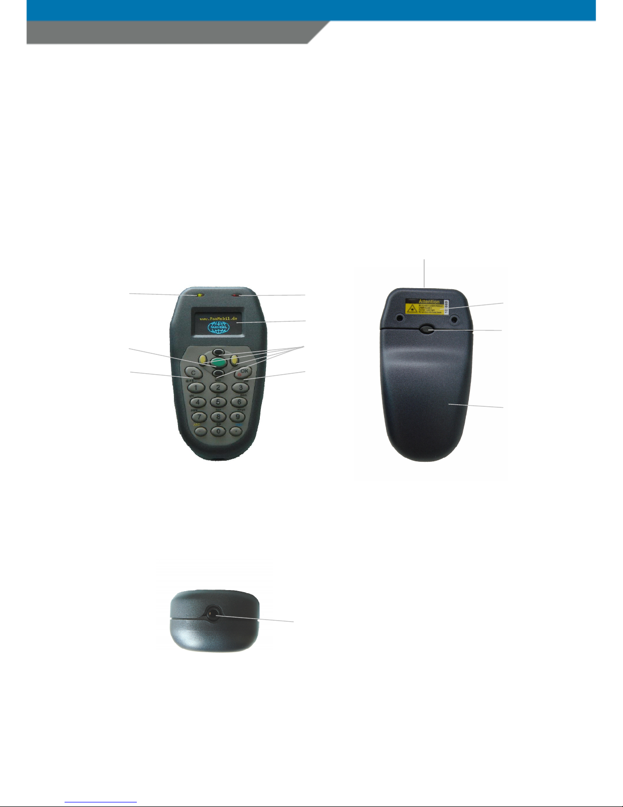
No. Description Function
1 Le t LED indicator Indicates green light when power ON
red light when charging the battery
2 Right LED indicator Indicates green light when triggered to read barcode
blue light when a Bluetooth connection is established
3 OLED display 128x64 ull graphic display
4 Basic trigger key Trigger or the internal laser engine to read 1D barcodes
5 Navigation key’s In menu mode the UP or DOWN navigation key is used to
highlight the chosen option.
LEFT navigation key to SELECT the highlighted option.
RIGHT navigation key to go one step back to the previous option
menu.
In edit mode the navigation keys are used to move the cursor UP,
DOWN, LEFT or RIGHT.
6 Clear key In edit mode this key is used to delete the last character input
when pressed once.
Holding this key pressed or 2 seconds does clear the complete
row.
On G7KLOBTCL1 Version this key is used to clear the screen.
7 OK and power key When the device is switched OFF, press this key shortly to power
the device ON. I the device is already powered ON, press and
hold this key or 3 seconds to power the device OFF
In message mode press this key shortly to apply a message.
In edit mode press this key shortly to have a Line eed
8 Red laser protect
window
Protects the laser engine against dust and damage
Keep this window clean to insure scan barcodes
9 Product label Find here the device serial number
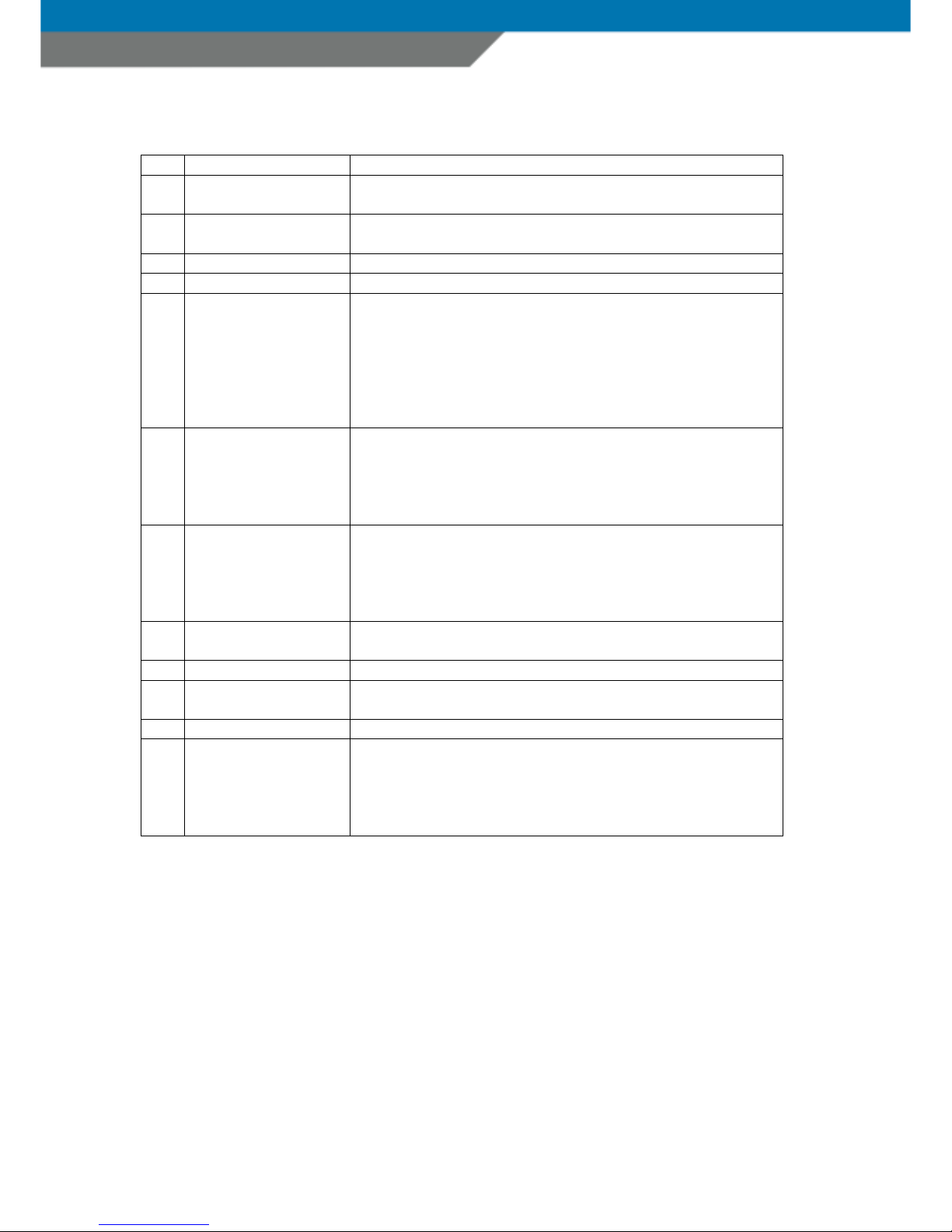
10 Battery cover release
button
Press this button and pull the battery cover in direction o
inter ace connector to access the battery
11 Battery cover Do not use the basic device without the battery cover.
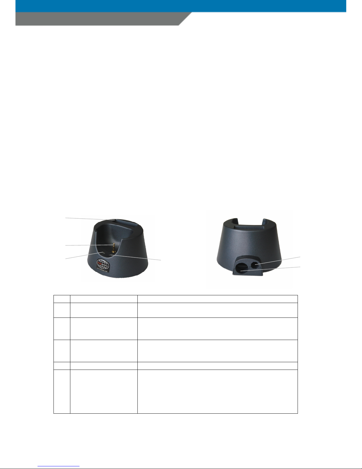
12 Main RS232 inter ace COM1 RS232C inter ace or data trans er and battery charging
when the device is placed in it’s cradle or a cable is directly
connected.
Do not connect with power supply directly.
Only recharge via cradle on serial-interface cable.