Greeter Setup
The greeter module stores prerecorded messages and plays them back when
vehicles arrive. You can record a series of messages then select or combine
them to convey standard messages and reduce time and errors.
Enter the Greeter Configuration Menu
All of the greeter settings are located in a top-level “Greeter Setup” configura-
tion menu. Perform the following procedure to enter the greeter configuration
menu:
1. Enter the base station configuration mode.
2. G5: Select Greeter Menu from the Main Menu. XT-1: Press and release Mode
until Greeter Setup Menu appears.
Record (Store) New Greeter, Reminder and Alert Messages
Perform the following procedure to record (store) a new greeter message using
a headset:
Note: If you store a new greeter message in an occupied slot, the old greeter
message will be permanently erased. Each recorded message can be no more
than 10 seconds long for G5; 8 seconds long for XT-1. G5 shortcut: From the
Main Menu, press the Right Arrow key to quickly access the Record Menu.
1. Put on a working headset with battery inserted and the power on.
2. At G5 basestation, enter the Greeter Menu. XT-1: Enter the greeter
configuration menu.
3. Select 2 Record Messages > Record Message >XX< where “XX” represents
the greeting number you want to record (1–16).
4. Scroll to and select Rec.
5. Press and hold the Page button on the headset.
6. Press and release Service on the base station and speak the messageyou
want to record while continuing to hold the Page button on the headset.
7. When finished, press and release Service, then release the Page button.
8. To hear the new greeting played back, scroll to Play and press Service.
Select Message Playback Schedule
The system allows you to record and store Greeter, Alert and Reminder
messages. G5: You can store up to a maximum of 16 messages, which can be a
combination of Greeter, Alert or Reminders. XT-1: You can store up to 8 greeter
messages, up to 16 reminder messages or up to 4 alert messages. You may
then select one or more of them to be played at any given time.
Perform the following procedures to schedule a message for play:
1. Enter the Greeter Menu.
2. Select 4 Message Daypart Definitions.
3. Configure start and end times for up to 12 dayparts.
4. G5 only: Select 5 Greeter Message Properties.
5. G5 only: Configure all Greeter message properties.
6. Next, select 6 Alert & Reminder Message Properties.
7. Configure each alert and reminder message
8. Select 1 Message Activation.
9. Select Msg. >XX< where “XX” represents the message number you want to
schedule.
10. Select “Yes” for each active daypart.
11.Scroll to the <MON> field, select the next day, and repeat the daypart
activation for each day of the week.
12. Set Act. to [Yes] to activate the weekly schedule for that message.
Change Basic Volume Settings
Note: All volume settings should be adjusted during normal or peak business
hours. Adjusting them during slow times will likely produce volume settings
that are too low.
Note: Inbound and outbound are always defined from the perspective of the
headset.
G5 only: For Dual Lane Operations, at any time while configuring the basesta-
tion or while on the Run Screen, you can switch the display screen to show Lane
1 or Lane 2 settings by pressing the Lane button on the keypad.
Inbound Microphone Volume
Changing the inbound microphone volume affects the sound volume coming
from the customer order point microphone. To turn up or down the inbound
microphone:
1. Enter the configuration mode. G5: Select System Menu.
2. Enter a new value for 01 Drivethru Volume > Inbound Mic Volume. The range
is 0 (silent) to 20 (maximum).
Outbound Talk Volume
Changing the outbound talk volume affects the volume of the speaker at the
customer order point.
Note: To avoid feedback, set the outbound talk volume as low as possible.
To change the outbound talk volume:
1. Enter the configuration mode. G5: Select System Menu.
2. Enter a new value for 01 Drivethru Volume > Outbound Talk Volume. The
range is 0 (silent) to 20 (maximum).
Vehicle Alert Volume
Changing the vehicle alert volume affects the volume of the vehicle alert signal
on the headsets. To change the vehicle alert volume:
1. Enter the configuration mode. G5: Select System Menu.
2. Select a new value for 01 Drivethru Volume > Vehicle Alert Volume. The
range is 0 (silent) to 20 (maximum).
Outbound Greeter Message Volume
Changing the outbound greeter message volume affects the sound volume of
the custom greeting messages and the system internal greetings (“Store
Closed” and “Please Pull Ahead”).
To turn up or down the greeter message volume:
1. Enter the configuration mode. G5: Select System Menu.
2. Select a new value for 01 Drivethru Volume > Greeter Message Volume. The
range is 0 (silent) to 20 (maximum).
Night Volume
You can assign a standard reduction in the volume level of the customer order
point speaker for night hours when lower volume is typically required. With the
night volume set, the system automatically adjusts the volume during night
hours, then back to normal during the day. To change the night volume setting:
1. Enter the configuration mode. G5: Select System Menu.
2. Select a new value for 03 Night Volume > Reduce Drive-Thru Volume At Night
By. The range is 0 (silent) to the current day volume level (maximum).
Note: Night Volume is never higher than Day Volume. Night volume reduction is
a subtracted value, not the resulting level; therefore, if it is the same as the day
volume level, the speaker will turn off at night. You cannot change the day
outbound talk volume on this screen, only the reduction amount identified
above.
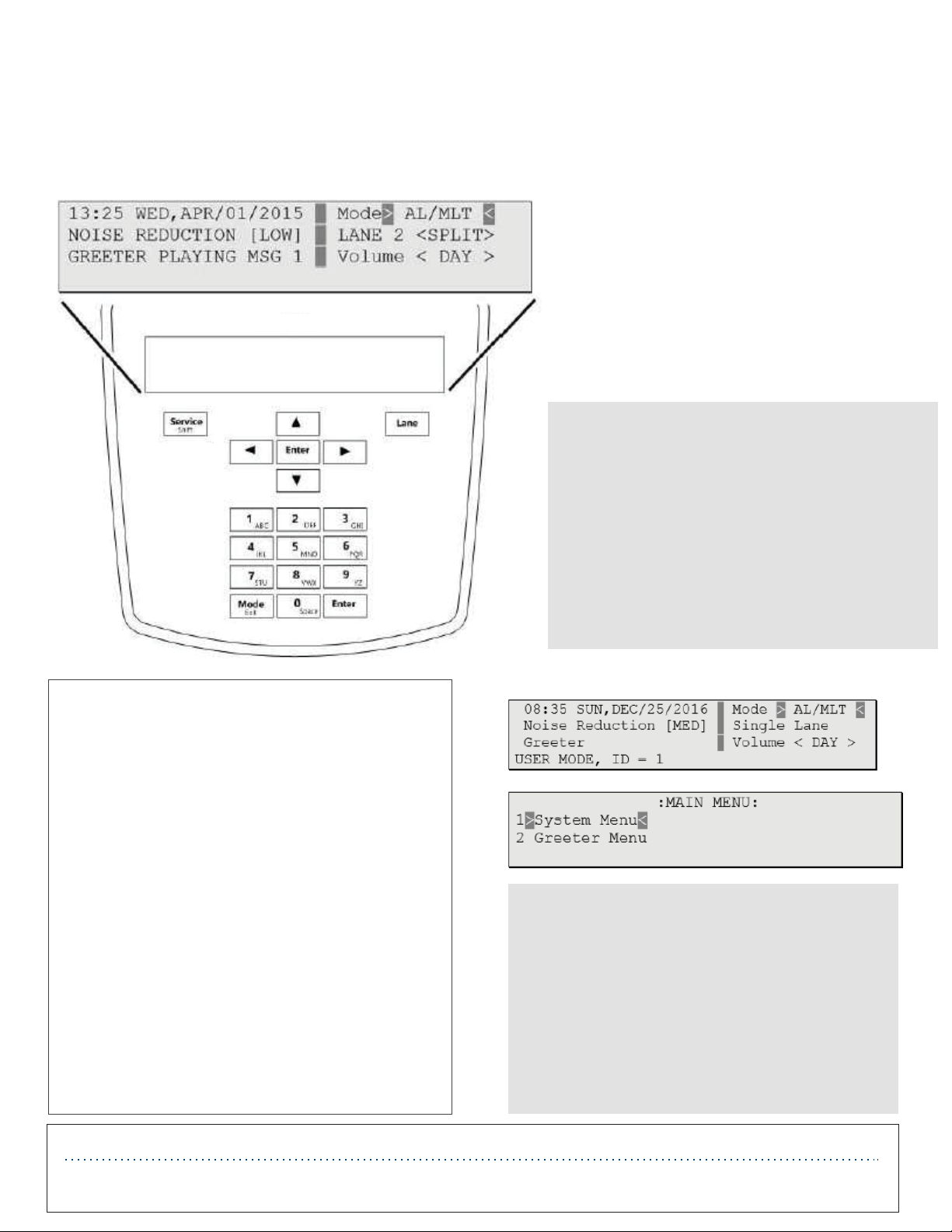
Enter Configuration Mode
Configuration mode is a passcode-protected area that contains most of the configuration options for the base station systems. With your user access, you
can set up all the functionality of the G5 Basestation (G5) and the Model XT-1 Basestation (XT-1). To enter the Configuration mode:
1. Enter your user passcode.
2. Press and release Mode key.
3. The display will show the username and ID number (e.g., User1 ID = 1)