Table 3: Options
[1] Ta m p e r R e c o g n i t i o n OFF† = Disabled ON = Enabled (Z8)
[2] PGM Deactivation OFF† = Deact. Event ON = PGM timer
[3] PGM Normal State OFF† = N.O. ON = N.C.
[4] PGM Base time OFF† = 1 sec. ON = 1 min.
(Default = all inputs @ 600ms)
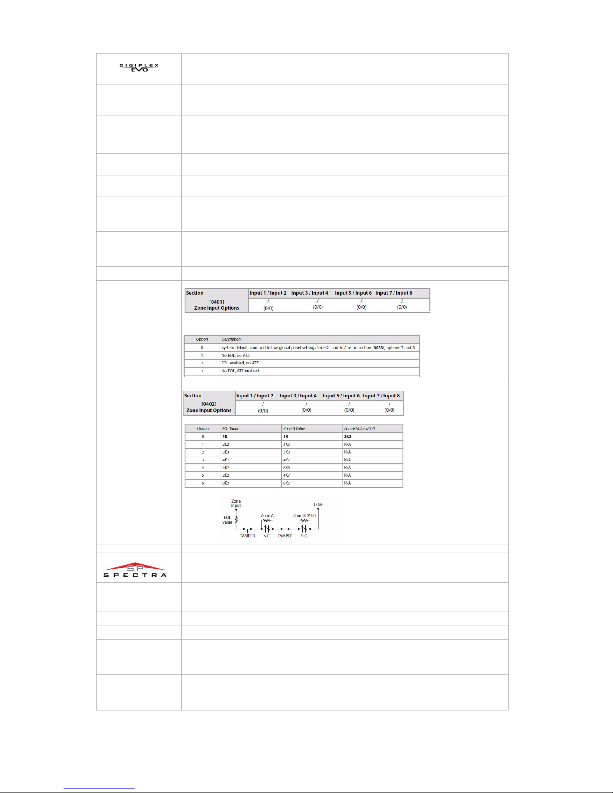
Even numbered sections represent inputs terminals Z1 to Z8. Using [] and [] keys. Select a Base Time value from 000 to 002. Press [ENTER].
000= Input Speed is X by 15 milliseconds.
001= Input Speed is X by 1 second.
002= Input Speed is X by 1 minute.
Odd numbered sections represent inputs Z1 to Z8. Enter a 3-digit decimal time value (000 to 255). Multiply by the Input Speed.
Enter a 3-digit decimal value (001-255). Multiply by the PGM Base Time Selection.
__/__/__ Event Group
__/__/__ Feature Group
__/__/__ Start# Set the range within the Feature Group
__/__/__ End# Set the range within the Feature Group
__/__/__ Event Group
__/__/__ Feature Group
__/__/__ Start# Set the range within the Feature Group
__/__/__ End# Set the range within the Feature Group
Activate PGM for 8 seconds to verify if the PGM is functioning properly.
By default, all options are configured as “0”. This means that all zone inputs will follow the global setting at panel section [3033], options 7 and 8. However, if
you change the value from 1 to 4, the inputs will follow the desired settings as shown below.:
†Default Setting / *Only Event Groups 000 to 055 can be used. See PGM Table in the panel’s Programming Guide.
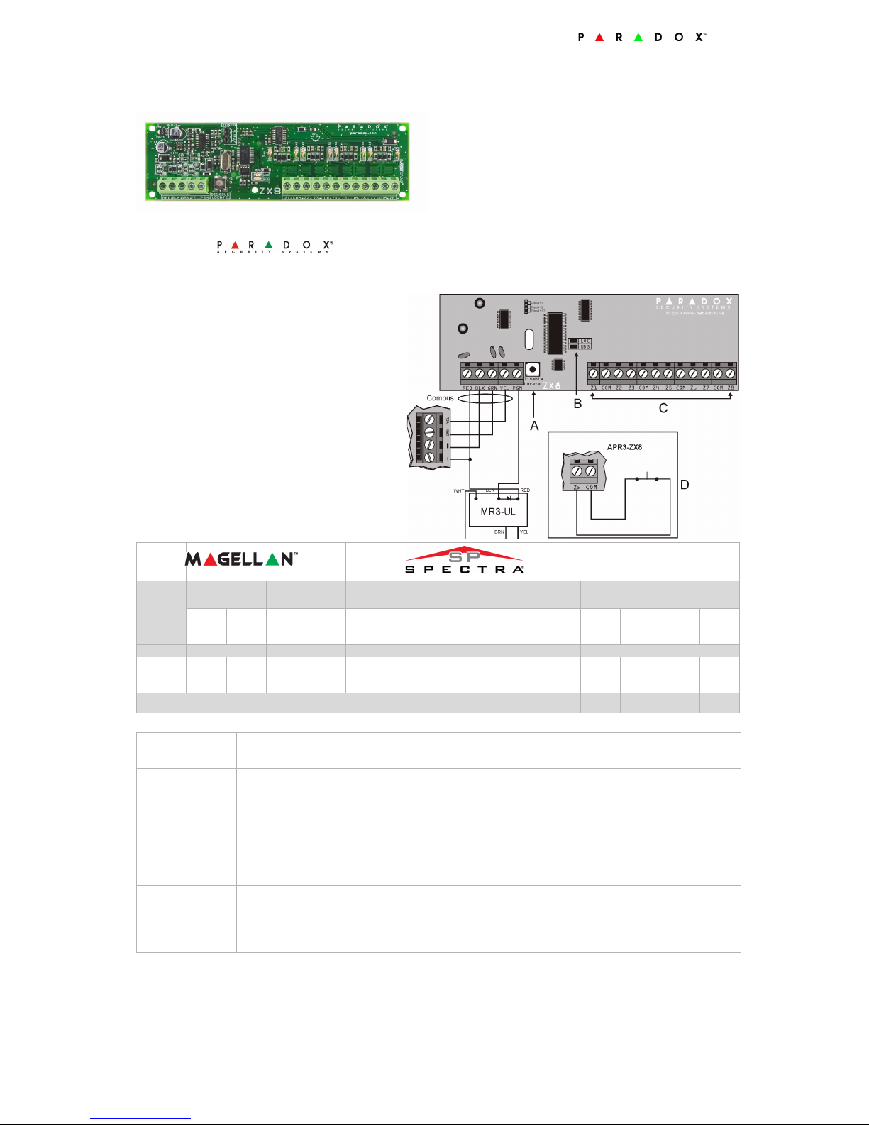
Programming Method
[1] EOL Zones OFF = No EOL ON = With EOL
[2] Ta m p e r R e c o g n i t i o n OFF = Disabled ON = Enabled (Z1)
[3] PGM Follows Global PGM OFF = Disabled ON = Enabled
Enable zone inputs. Options [1] to [8], represent inputs Z1 to Z8.
__/__/__ 000 - 255 sec. 000 = Follow Deactivation Event.
__/__ Event Group [60] Tamper zone opened
[61] Tamper zone closed
__/__ Sub-Group [1] to [8] Zone input Z1 to Z8
__/__ Partition Not Used: Enter [00]
__/__ Event Group [60] Tamper zone opened
[61] Tamper zone closed
__/__ Sub-Group [1] to [8] Zone input Z1 to Z8
__/__ Partition Not Used: Enter [00]
Warranty
For complete warranty information on this product please refer to the Limited Warranty Statement found on the website www.paradox.com/terms. Your use of the Paradox product signifies your acceptance of all warranty terms and conditions.
Magellan, Spectra SP, Digiplex and Digiplex EVO are trademarks or registered trademarks of Paradox Security Systems Ltd. or its affiliates in Canada, the United States and/or other countries. For the latest information on products approvals, such as UL and CE, please visit www.paradox.com. © 2010 Paradox Security Systems Ltd. All rights reserved. Specifications
may change without prior notice. One or more of the following US patents may apply: 7046142, 6215399, 6111256, 6104319, 5920259, 5886632, 5721542, 5287111, 5119069, 5077549 and RE39406 and other pending patents may apply. Canadian and international patents may also apply.
Programming Method
1. Hold [0] key+ [INSTALLER CODE]
2. Enter section [953] (DGP-848) [4003] (EVO)
3. Enter module’s 8-digit [SERIAL NUMBER]
4. Enter [SECTION] and turn desired option ON/OFF or enter the required data
Sections
[001]
Options
[002]-[016]
Even Numbered
Input Speed (Base Time Selection)
[003]-[017]
Odd Numbered
Input Speed (Time Value)
[018] PGM Timer
[019]
[020]
[021]
[022]
Activation Event*
[023]
[024]
[025]
[026]
Deactivation Event*
[030] PGM Test Mode
[401] EOL/ATZ Options per Zone Input
Zone Input Option Individual Settings
[402] Selectable Input Resistor for EOL and Contact
Zone Input Option Individual Settings
1. [ENTER] + [INSTALLER CODE]
2. Enter [SECTION]and turn desired option ON/OFF or enter the required data
[650] Tamper Recognition
[651] Zone Assignment
[655] PGM Timer
[656] PGM Activation Event
[657] PGM Deactivation Event