Parallax Boe-Bot Tank Treads User manual

1 Parallax, Inc. •Boe-Bot Tank Tread Kit (#28106) 03/2004
599 Menlo Drive, Suite 100
Rocklin, California 95765, USA
Office: (916) 624-8333
Fax: (916) 624-8003
General: info@parallax.com
Technical: support@parallax.com
Web Site: www.parallax.com
Educational: www.stampsinclass.com
Boe-Bot Tank Treads (#28106)
Treaded Addition for the Boe-Bot
Introduction
Treads let the Boe-Bot to access more varied terrain such as carpet, small rocks or imperfect surfaces.
This kit involves the removal of the Boe-Bots wheels and addition of a treaded drive train.
Packing List
Verify the contents of your Boe-Bot Tank Tread App Kit to include:
Documentation
(2) metal sides –720-28106
(1) Plastic wheel set and (1) Rubber tread set –721-28106
(2) Servo horn (standard or disk) - 725-00013
(8) 4-40 Machine Screws, 1/4”–700-00028
(6) 4-40 Machine Screws, 3/8”–700-00002
(8) 4-40 Machine Screws, 7/8”–700-00007
(22) 4-40 Nut –700-00003
(2) 1.5”screw –710-00008
(2) 1.25”standoff –713-00003
If any parts are missing contact Parallax immediately for replacements.
Tools Needed
You will need a Philips screw driver, wrench and a 3/32”drill (or Exacto type knife).
Assembly
From the set of wheels cut out the following and trim off any burs:
(2) large wheels (with teeth)
(2) large wheels (no teeth)
(6) medium sized wheels (no teeth)
The remaining wheels are not used.

2 Parallax, Inc. •Boe-Bot Tank Tread Kit (#28106) 03/2004
The servo horn will need four of the holes enlarged for the 4-40 screws. The holes need to be smaller
than the screw so that when the screws are inserted they will make their own threads. You can drill the
holes using a 3/32”drill bit or use an X-acto knife to enlarge the holes as shown in figures 1 and 2 If you
are using the knife be sure not to over enlarge the holes. By reaming with the knife a little from the top
and bottom, the hole will be more uniform in size.
3/32”
(2.2 mm)
Figure 1: Modify Disk Horn with Drill or Knife
Modify the disk servo horn by drilling or reaming the middle holes larger. If using a knife ream from the
top and bottom but leave material for threads to be made.
Wire cutters work well for trimming off the servo horn ends.
3/32”
(2.2 mm)
Figure 2: Modify Standard Servo Horn with Drill or Knife
Modify the standard servo horn by drilling or reaming the inner holes larger. If using a knife ream from
the top and bottom but leave material for threads to be made.
Using the ¼”screws attach the two large wheels (with teeth) to the servo horns as shown in Figure 3.
Figure 3: Mounting the Wheel to Servo Horn
Mounting the wheel with teeth to the servo horn with ¼”screws.

3 Parallax, Inc. •Boe-Bot Tank Tread Kit (#28106) 03/2004
Attach the 7/8”screws and nuts to the remaining wheels as shown and set aside. See Figure 4.
Figure 4: Attach 7/8”Screws to Wheels
Attaching the 7/8”screws to the wheels (2 large and 6 medium in size).
Remove the wheels from your Boe-Bot. The servos should be mounted with the head toward the rear ball
wheel as in Figure 5.
w
w
w
.
p
a
r
a
l
l
a
x
.
c
o
m
c
o
n
t
i
n
u
o
u
s
r
o
t
a
t
i
o
n
wrong way
w
w
w
.
p
a
r
a
l
l
a
x
.
c
o
m
c
o
n
t
i
n
u
o
u
s
r
o
t
a
t
i
o
n
right way
Figure 5: Servos are Mounted on the Outside of the Chassis

4 Parallax, Inc. •Boe-Bot Tank Tread Kit (#28106) 03/2004
Confirm that the servos are mounted correctly.
If your servos are mounted the opposite way, remove them and remount as shown. Attach the sides
using 3/8”screws and nuts. Then attach the servo horn (with wheel) using the screw that came with the
servo. See Figure 6.
Figure 6: Attach Sides with 3/8”Screws and Attach Servo Horn with Wheel
Attach the remaining wheels by first tightening the nut on the wheel then loosening it a ¼ -1/3 a turn.
Mount with a nut on each side of the frame. When the two nuts on each wheel are tightened, check to
see that the wheel and outside nut has a small gap to allow for easy rolling. See Figure 7.
Figure 7: Mount Roller Wheels
When mounting the wheels make sure there is a small gap between the wheel and the nut so the wheel
can roll easily. Leave a small gap so the wheel can turn freely. Mount the remaining wheels shown in
Figure 8.
Figure 8: Mount the Remaining Wheels with 3/8”Screws

5 Parallax, Inc. •Boe-Bot Tank Tread Kit (#28106) 03/2004
Separate all the rubber tread pieces and connect together as shown in Figure 9.
Figure 9: Connect the Tread Links
Each loop contains 1 long, 2 medium and 2 short treads.
Check each wheel to make sure it rolls without binding. If any wheels bind, loosen the nut and remount
to maintain a small gap between the wheel and nut. Stretch the tread over the wheels and the assembly
is done.
P15
P14
P13
P12
P11
P10
P9
P8
P7
P6
P5
P4
P3
P2
P1
P0
X2
X3 Vdd VssVin
Board of Education
© 2000-2003
Rev C
Vdd
Black
Red
X4 X5
15 14 13 12
To Servos
Figure 10: Installing the Standoff “Protectors”
The Boe-Bot’s breadboard circuit can be protected by installing (2) 1.5”screws and (2) 1.25”spacers on
the front of the Board of Education.

6 Parallax, Inc. •Boe-Bot Tank Tread Kit (#28106) 03/2004
Application with the Memsic 2125 Accelerometer Chip
The Memsic 2125 dual-channel accelerometer can be used with your Boe-Bot Tank Tread kit to keep the
Boe-Bot from flipping over when it encounters very uneven terrain.
Parts Required
This project requires the Boe-Bot Full Kit, Memsic 2125 Accelerometer and the Boe-Bot Tank Tread Kit.
Specifically, you will be adding the following components to your Board of Education:
(2) Infrared transmitter assemblies (#350-00017)
(2) Infrared receivers (#350-00014)
(2) 1K ohm resistor 1/4 watt (#150-01020)
220 ohm resistor 1/4 watt (#150-02210)
(1) Memsic 2125 Dual-axis Accelerometer (#28017)
Wiring Diagram and Pictorial
P15
P14
P13
P12
P11
P10
P7
P6
P3
P1
P9
P8
P5
P4
P2
P0
X2
X3 Vdd VssVin
Board of Education
© 2000-2003
Rev C
Vdd
Black
Red
X4 X5
15 14 13 12
To Servos

7 Parallax, Inc. •Boe-Bot Tank Tread Kit (#28106) 03/2004
Schematic
1
2
4
3
5
6
X
Vss
Vss
P5
P4
+5
Memsic
2125
Vdd
Vss
P0 220
Vdd
Vss
P9 220
P8
IR
LED
Vss
1 k
P1
IR
LED
Vss
1 k

8 Parallax, Inc. •Boe-Bot Tank Tread Kit (#28106) 03/2004
Stamp Code
' =========================================================================
'
' File...... Advanced_Tank_Bot.BS2
' Purpose... Tank Bot with Tilt Sensing
' Author.... Parallax
' Started...
' Updated... 12 APRIL 2004
'
' {$STAMP BS2}
' {$PBASIC 2.5}
'
' =========================================================================
' -----[ Program Description ]---------------------------------------------
'
' This program incorporates the Memsic 2125 accelerometer into the BOE-Bot
' tank kit to allow the tank to exlore uneven terrain without tipping over.
' -----[ Revision History ]------------------------------------------------
' -----[ I/O Definitions ]-------------------------------------------------
LfIrOut PIN 8 ' left IR LED output
LfIrIn PIN 9 ' left IR sensor input
RtIrOut PIN 1 ' right IR LED output
RtIrIn PIN 0 ' right IR sensor input
LMotor PIN 13 ' left servo motor
RMotor PIN 12 ' right servo motor
TiltX PIN 4 ' X tilt input
TiltY PIN 5 ' Y tilt input
' -----[ Constants ]-------------------------------------------------------
LFwd CON 1000 ' left motor forward
LStop CON 750 ' left motor stop
LRev CON 500 ' left motor reverse
RFwd CON 500 ' right motor forward
RStop CON 750 ' right motor stop
RRev CON 1000 ' right motor reverse
IsHigh CON 1 ' high-going pulse
IsLow CON 0 ' low-going pulse
YThresh CON 20 ' Y tilt threshold
' -----[ Variables ]-------------------------------------------------------
pulses VAR Byte ' counter for servo control

9 Parallax, Inc. •Boe-Bot Tank Tread Kit (#28106) 03/2004
irBits VAR Nib ' ir detection bits
irLeft VAR irBits.BIT1 ' left IR detection
irRight VAR irBits.BIT0 ' right IR detection
xAxis VAR Word ' x-axis tilt reading
yAxis VAR Word ' y-axis tilt reading
' -----[ EEPROM Data ]-----------------------------------------------------
' -----[ Initialization ]--------------------------------------------------
Reset:
LOW LMotor ' initialize motor outputs
LOW RMotor
' -----[ Program Code ]----------------------------------------------------
Main:
DO
GOSUB Check_Level ' verify terrain okay
' navigate around obstacles
GOSUB Read_IR_Sensors
ON irBits GOSUB Forward, Go_Left, Go_Right, U_Turn
LOOP
END
' -----[ Subroutines ]-----------------------------------------------------
Check_Level:
PULSIN TiltY, IsHigh, yAxis ' check longitudinal tilt
yAxis = yAxis / 100 ' filter reading
IF (yAxis =< YThresh) THEN ' if terrain too steep
GOSUB U_Turn ' ... and turn around
ENDIF
RETURN
Read_IR_Sensors:
irBits = %00
FREQOUT LfIrOut, 1, 38500 ' modulate left IR LED
irLeft = ~LfIrIn ' read input (1 = target)
FREQOUT RtIrOut, 1, 38500 ' modulate right IR LED
irRight = ~RtIrIn ' read input (1 = target)
RETURN
Forward: ' move tank forward
FOR pulses = 1 TO 5
PULSOUT LMotor, LFwd
PULSOUT RMotor, RFwd
PAUSE 20
NEXT
RETURN

10 Parallax, Inc. •Boe-Bot Tank Tread Kit (#28106) 03/2004
Go_Left: ' turn to left
FOR pulses = 1 TO 15
PULSOUT LMotor, LStop
PULSOUT RMotor, RFwd
PAUSE 20
NEXT
RETURN
Go_Right: ' turn to right
FOR pulses = 1 TO 15
PULSOUT LMotor, LFwd
PULSOUT RMotor, RStop
PAUSE 20
NEXT
RETURN
U_Turn: ' turn around
IF (yAxis > YThresh) THEN
GOSUB Back_Up ' back-up if flat terrain
ENDIF
PULSIN TiltX, IsHigh, xAxis ' check longitudinal tilt
xAxis = xAxis / 100 ' filter reading
IF (xAxis < 24) THEN ' turn left
FOR pulses = 1 TO 60
PULSOUT LMotor, LRev
PULSOUT RMotor, RFwd
PAUSE 20
NEXT
ELSE ' turn right
FOR pulses = 1 TO 60
PULSOUT LMotor, LFwd
PULSOUT RMotor, RRev
PAUSE 20
NEXT
ENDIF
RETURN
Back_Up: ' back up a bit
FOR pulses = 1 TO 10
PULSOUT LMotor, LRev
PULSOUT RMotor, RRev
PAUSE 20
NEXT
RETURN
This manual suits for next models
1
Table of contents
Other Parallax Robotics manuals
Parallax
Parallax 28985 User manual

Parallax
Parallax 28195 User manual

Parallax
Parallax S2 User guide

Parallax
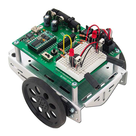
Parallax Boe-Bot User manual
Parallax
Parallax 30055 User manual
Parallax
Parallax 28990 User manual
Parallax
Parallax 28106 User manual
Parallax
Parallax Boe-Bot User manual
Parallax
Parallax Boe-Bot Whisker Kit User manual
Parallax
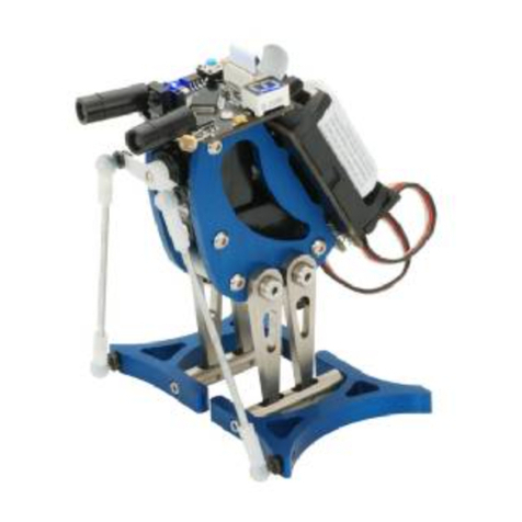
Parallax Penguin User manual
