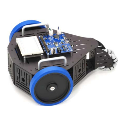
Parallax SumoBot WX Board User manual

Web Store: www.parallax.com
Tutorials: learn.parallax.com
Sales: sales@parallax.com
Tech Support: support@parallax.com
Office: (916) 624-8333
Educator Hotline: (916) 701-8625
Sales: (888) 512-1024
Tech Support: (888) 997-8267
SumoBot WX Board (#32132)
The SumoBot WX board sports a socket for the Propeller FLiP Multicore Microcontroller
Module (#32123), providing power and I/O and connections to the wide array of
on-board peripheral sockets and headers. Clear labelling, status indicator LEDs, and
on-board piezospeaker support successful project building and operation.
Designed specifically for the SumoBot WX Robot Competition Kit (#32134), the board's
corner mounting holes align with the SumoBot chassis. 3-pin servo ports and an
onboard boost regulator support robot locomotion. Additional headers and sockets
accommodate sensors included in the Competition Kit, as well as optional accessories.
The WX socket accepts a Parallax WX ESP8266 WiFi - DIP module (#32420D) for
optional wireless programming and communication.
Features and Specifications
●Socket for the Propeller FLiP multicore microcontroller module
●Powerful onboard 5 V, 350 mA boost regulator with short-circuit and overcurrent
fault protection
●WX Socket for optional wireless programming and communication with a Parallax
WX ESP8266 WiFi - DIP module
●LEDs on the board for power switch position, WiFi ASC, DO and DI, and
low-battery warning
●Reset button PCB resets the Propeller FLiP module
●2.1mm ID center-positive DC Jack for 4.8–8.4 VDC input
●Headers for 3.3V and 5V sensors, including AUX, QTI, PING, Memsic MX2125
and IR emitters/receivers
●Onboard piezospeaker
●Operating temperature: -4 to +185 °F (-20 to +85 °C)
●PCB Dimensions: 3.07 x 3.15 in (78 x 80 mm)
Application Ideas
●Build, program and battle! High-quality SumoBot Robot for the mini-sumo
competition ring
●Learning robot building and programming
●Compact SumoBotWX system PCB suitable for custom products
Resources and Downloads
For SumoBot WX Board documentation, software, and example programs, see the
product page: go to www.parallax.com and search #32132.
Copyright © Parallax Inc. SumoBot WX Board (#32132) v1.0 8/14/2020 Page 1 of 9

Features & Descriptions
1) Propeller FLiP Module Socket
The Propeller FLiP Multicore Microcontroller Module plugs into this DIP socket, which
brings Propeller I/O pin connections P1-P31 to all of the headers and sockets; see the
Pin Definitions and Ratings table. For programming, the USB cable plugs directly into
the FLiP socket.
2) PING))) Distance Sensor Sockets
This header accepts the 0.1” pins on the PING))) Ultrasonic Distance Sensor (#28015)
and LaserPING 2m Rangefinder (#28041) modules.
Copyright © Parallax Inc. SumoBot WX Board (#32132) v1.1 8/17/2020 Page 2 of 9

This header is a two-row socket, with each row the inverse of the other. This
configuration allows the sensor module to be plugged in from either the TOP or
BOTTOM of the PCB. On the assembled SumoBot WX, the Ping))) Ultrasonic sensor fits
best under the board, whereas the LaserPING fits well on the top.
You must only connect one PING module to the socket, either in
the TOP or BOTTOM position. You must never connect to both sides
(or socket rows) at the same time!
3) Piezospeaker
The piezospeaker is connected to P20; drive with frequency-out signals in the 300 to
5000 Hz range.
4) Mounting Holes
The four plated mounting holes are positioned to attach the SumoBot WX Board to the
robot chassis included in the SumoBot WX Competition Kit.
5) UART Switch
The UART slide switch allows the user to change which Propeller I/O pins are connected
to the WiFi Module socket's TX/RX serial I/O pins.
With the switch in the top position, pins P30 and P31 are connected to the WiFi module
serial pins, which allows for wireless programming of the Propeller on the FLiP module.
With the switch in the bottom, pins P24 and P25 are connected to the WiFi module,
which is useful for transmitting serial data in certain situations, such as when the
Propeller is being programmed by a USB connection that would interfere with data on
P30 and P31.
Another common use for the SER2 connection is when using the FLiP to program the
WiFi module network settings.
Switch position
FLiP pin
Radio module pin
PROG (31/30)
P31 (Propeller FLiP RX)
TX (DO)
P30 (Propeller FLiP TX)
RX (DI)
SER2 (25/24)
P25 (Propeller FLiP RX)
TX (DO)
P24 (Propeller FLiP TX)
RX (DI)
Copyright © Parallax Inc. SumoBot WX Board (#32132) v1.1 8/17/2020 Page 3 of 9

6) ESP2866 WiFi Module DIP Socket
A Parallax WX ESP8266 WiFi Module - DIP (#32420D) can be plugged into this socket.
This equips the SumoBot WX board to wirelessly program the Propeller on the FLiP
module, as well as support other radio applications. When installed, the WiFi module
interacts with the ASC LED, D1 & D0 LEDs, and DTR / RESn Header.
7) ASC LED
The blue ASC LED indicates the connection status of the attached radio module.
When SumoBot WX has the Parallax WiFi module installed, the blue LED will blink
occasionally while the WiFi module is connected to a wireless network, and the blink
timing can be used to identify the connection status of the wireless module.
Refer to the Parallax WiFi module product guide for the latest information about the
ASC LED behavior, available from the 32420D product page at www.parallax.com.
8) DI and DO LEDs
The DI and DO LEDs are wired from the perspective of the radio module. These can be
used to diagnose connection problems or monitor information flow between the radio
module and the Propeller microcontroller.
The red DI LED indicates communication to the radio module RX pin from the Propeller
FLiP module’s Propeller microcontroller TX pin (P30 or P24).
The blue DO LED indicates communication from the radio module to the Propeller
microcontroller’s RX pin (P31 or P25).
Note that the Propeller module TX and RX pin selection can be altered by the UART
switch.
9) DTR / RESn Header
The DTR to RESn header is pre-fitted with a 2mm shunt jumper which must be kept
installed to enable programming of the FLiP module.
The jumper may be removed (and retained!) to prevent the radio module from being
able to remotely program or reset the Propeller FLiP module, as a protection against
rogue competitors from resetting the robot during battle!
Copyright © Parallax Inc. SumoBot WX Board (#32132) v1.1 8/17/2020 Page 4 of 9

10) Battery Low LED
The battery low LED indicates when the batteries need changing. The LED blinks
occasionally as the voltage level nears the end of its capacity, lights solidly with 5-10
minutes runtime left. Timing will vary depending on the battery type and current
demands. The battery low LED may flash briefly when power is first connected, this is
normal and can be ignored.
The battery low signal is also available at one of the so you could monitor for this
condition and reduce current demands for the last stages of battle, or send a message
over WiFi to the robot operator.
11) Reset Button
The reset button at the bottom-right corner of the PCB holds the Propeller FLiP
microcontroller in reset whilst pressed. When multiple robots are about to battle, it can
be convenient for both teams to hold the reset buttons, and release them when it’s
time to start the robots! This button resets the Propeller microcontroller without
affecting power to the rest of the board. The Propeller microcontroller can also be reset
using the small RESET button located under the top edge of the FLiP module.
12) Power Switch with LEDs
The power switch in position 0 disconnects the input power supply from the entire
SumoBot WX board AND holds the Propeller FLiP in reset if it has an external power
source connected to its USB port. Position 1 enables everything except power to the
servo ports. Position 2 also enables power to the servo ports.
Two green power LEDs indicate when the switch is in Position 1 (1 on) or 2 (both on).
13) Anchor Holes
There are seven unplated anchor holes around the PCB, useful for mounting additional
hardware or securing servo and sensor cables with cable ties.
14) MEMSIC MX2125 Header
The MX2125 designated pads are located under the FLiP module socket, and accept the
MEMSIC 2125 Dual-axis Accelerometer (#28017).
Propeller I/O pins P21 and P22 connect to the MX2125 socket via 240-ohm series
resistors. These connections could be used as general purpose I/O’s instead of the
accelerometer function.
Copyright © Parallax Inc. SumoBot WX Board (#32132) v1.1 8/17/2020 Page 5 of 9

15) Servo Headers
The servo headers are labelled L (Left, P26) and R (Right, P27) servo motors, and are
configured to match the orientation of the Parallax standard BRW (Black Red White)
servo cable colors. Power output is enabled when the Power switch is in position 2, and
the voltage level is set by the battery pack voltage connected to the DC Jack.
WARNING! Power In voltage sets the voltage at the servo headers.
Use an input voltage that does not exceed the maximum voltage
rating of the servo motors.
16) QTI Headers
The four QTI headers with 0.1” pitch pins are compatible with the Parallax QTI Sensors
(#555-27401) that are included in the SumoBot WX Competition kit. Note that the
Propeller I/O connection (P12–P15) is the center pin on each of these headers, unlike
the SERVO and AUX headers.
17) Power In DC Jack
The Power In DC Jack accepts a DC plug with a center-positive 5.5 mm outer diameter,
2mm pin diameter, such as the one on the 4AA battery holder included in the SumoBot
WX Competition Kit. Power input voltage range is 4.8-8.4 VDC.
WARNING! Power In voltage sets the voltage at the servo headers.
Use an input voltage that does not exceed the maximum voltage
rating of the servo motors.
18) AUX Headers
Four AUX 3-pin, 0.1” pitch headers are provided for the user to expand and customize
their application with additional accessories.
All four headers are arranged to match the standard Parallax cable color order,
Black-Red-White = Ground-Power-Signal. The top two AUX headers have 3.3V output,
and the bottom two have 5V output.
19) Bulk Capacitors
The SumoBot WX requires significant power during battle, especially as the servo
motors change direction and encounter friction which increases the current draw and
reduces voltage levels. The three large capacitors provide a reservoir of power to keep
the SumoBot WX powered during the toughest of battles!
Copyright © Parallax Inc. SumoBot WX Board (#32132) v1.1 8/17/2020 Page 6 of 9

20) Infrared Receiver Sockets (IR RX)
There are four 3-pin IR Receiver sockets spaced around the front edges of the SumoBot
PCB. Each turned-pin style socket with 0.1” pitch is compatible with the Infrared
Receivers (#350-00039) included in the SumoBot WX Competition Kit.
Each socket has 5V, GND, and an I/O pin connection for the IR receiver to send data to
the Propeller. The center GND pin is identified by a logo representing the IR receiver,
which shows the correct orientation for the receiver.
21) Infrared Transmitter Sockets (IR TX)
There are four 2-pin Infrared transmitter sockets spaced around the front edges of the
SumoBot PCB. Each is a turned-pin style socket with 0.1” pitch, compatible with the
Parallax IR Transmitter LEDs (#350-00003) included in the SumoBot WX Competition
Kit.
Each socket has a PWM-GND and an I/O pin connection for the Propeller to supply a
voltage signal to the IR Transmitter LED.
The PWM-GND pin is a special feature of the SumoBot WX, and enables fine control
over the IR TX LED brightness. Refer to the PWM-GND Op-Amp description below and
the schematic download at the SumoBot WX product page for more details.
22) PWM-GND Op-Amp
The four IR TX LEDs have a common GND connection controlled by an onboard
Op-Amp to allow fine control over the LED brightness and therefore IR receiver range.
To use the LEDs you must either set P23 low (for maximum brightness), or use PWM
code to set the voltage level higher, which will reduce the LEDs' brightness.
The LEDs have a nominal forward voltage of 1.4 V and the positive side of the LEDs are
driven at 3.3V, so you can raise the GND voltage from 0 V up to the difference between
the two, 1.9 V, to adjust the brightness. Experimentation is encouraged!
Specifications
Symbol
Description
Minimum
Typical
Maximum
Units
VIN *
Supply Voltage at DC Input Jack
4.8
6
8.4
V
IOUT_3.3V
Total available current output from all
headers marked as 3.3V
250
mA
IOUT_5V
Total available current output from all
headers marked as 5V
250
mA
VOUT_SERVO
Output voltage at servo headers
VIN - 0.3
V
* DO NOT exceed the maximum voltage rating of your servo motors!
Copyright © Parallax Inc. SumoBot WX Board (#32132) v1.1 8/17/2020 Page 7 of 9

Pin Definitions and Ratings
Pin Label
Type
Function
P0-P3
I/O
IR-RX Headers, tolerate 3.3V or 5V signals in, output 3.3V logic level
P4-P7
I/O
IR-TX Headers, output 3.3V logic level
P8-P9
I/O
AUX Headers with 3.3VOUT and 3.3V logic level.
P10-P11
I/O
AUX Headers with 5VOUT, tolerate 3.3V or 5V signals in, output 3.3V logic
level
P12-P15
I/O
QTI Headers with 5VOUT, tolerate 3.3V or 5V signals in, output 3.3V logic level
P16
O
5V Enable. Set pin as input to enable regulator (default mode).
Output low to disable 5V regulator.
P17
I
Low voltage signal. Normally high, this signal goes low when supply voltage
drops low, and is a warning to change the batteries soon and/or to disable
power to less crucial (and high power) functions, such as the WiFi module.
P18
I/O
WX_DBG - Connects to the debug output signal from the Parallax WiFi module
(if installed).
P19
I/O
Socket for PING))) or LaserPING Distance Sensor
P20
O
Piezospeaker
P21-P22
I/O
Memsic MX2125 expansion pads under the FLiP module
P23
O
Common IR TX LED GND. Set low to operate IR TX LEDs at full brightness, or
apply PWM signal to adjust brightness.
P24
O
Serial2 TTL Output (TX) to WiFi module (if installed)
P25
I
Serial2 TTL Input (RX) from WiFi module (if installed)
P26
O
Servo motor LEFT control signal. P26 LED on FLiP module will flash to indicate
left motor signal
P27
O
Servo motor RIGHT control signal. P27 LED on FLiP module will flash to
indicate right motor signal
P28-P29
I/O
FLiP I2C pins, not used by the SumoBot WX PCB. Refer to the Propeller FLiP
product page for the FLiP schematic for details about these pins.
P30
O
Propeller programming pin / Serial1 / TTL Output (TX) to WiFi module (if
installed)
P31
I
Propeller programming pin / Serial1 / TTL Input (RX) from WiFi module (if
installed)
DTR
O
DTR Signal from WiFi module (if installed), used to reset Propeller FLiP during
wireless programming. Disconnect this signal from RESn to disable wireless
programming.
RESn
I
RESET input to Propeller FLiP module. Set low to hold Propeller FLiP in reset
state.
GND
Power
Ground
DC JACK
Power
Power input to SumoBot WX
NC
-
No connection
5V
Power
5 V power output only when FLiP installed and power switch on. 5V output can
be disabled by 5V_Enable pin, P16.
3.3 V
Power
3.3 V power output only when FLiP installed and power switch on.
SERVO V
Power
Servo motor power output only when power switch is set to position 2.
Copyright © Parallax Inc. SumoBot WX Board (#32132) v1.1 8/17/2020 Page 8 of 9

Dimensions
PCB: 3.07 x 3.15 in (78 x 80 mm)
Mounting hole pitch: 2.75 in (70 mm)
Mounting hole diameter: 0.11 in (3 mm)
Cable tie / fixing hole diameter (qty 7): 0.125 in (3.2mm)
Revision History
Version 1.0: original release. V1.1: Corrected label 5 on features diagram.
Copyright © Parallax Inc. SumoBot WX Board (#32132) v1.1 8/17/2020 Page 9 of 9
This manual suits for next models
1
Table of contents
Other Parallax Robotics manuals

Parallax
Parallax 28985 User manual

Parallax
Parallax 30055 User manual

Parallax
Parallax Boe-Bot User manual

Parallax
Parallax 28106 User manual

Parallax
Parallax 28106 User manual

Parallax
Parallax S2 User guide

Parallax
Parallax 28990 User manual

Parallax
Parallax Boe-Bot Whisker Kit User manual

Parallax
Parallax Boe-Bot Tank Treads User manual

Parallax
Parallax Penguin User manual