Paramotor PXP Meter User manual

Welcome
PXP Meter
APP
to
“ Where you will
only find a problem,
if you have tried it
you can never
be without it ”
2

Index
3
4- When shopping includes
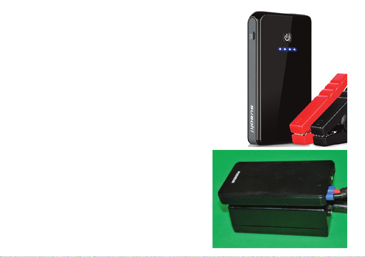
5- Battery - Types and installation
8- Simple Manual
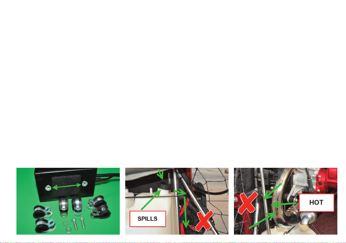
9- Switchboard Installation
11 - Sensor - Fuel Installation
12 - Sensor - RPM Installation
13 - Sensor - Pressure Installation
14 - Sensor - CHT Installation
15 - Sensor - EGT Installation
19 - Sensor - H2O Installation
20 - Installation Sensor - Cable Mass
21 - Installation Connectors
25 - Application - Installation Manual
27 - How We register
28 - First Notification
29 - How to connect the Bluetooth
31 - How to set up the Data
33 - Enter Fuel
34 - How to match the Bluetooth
35 - How We started
37 - Buttons and Data - Sound Button
38 - Data Batteries - Altitude
39 - Alarms
40 - RPM Alarm
41 - Battery Alarm
42 - Fuel Alarm
45 - CHT + EGT Alarms
46 - H2O Alarm
47 - EGT Data
48 - CHT + RPM Data
48 - Types of Revolutions
50 - Fuel data
52 - Fuel Marker
54 - Speed - Distances data
54 - Speed and Media Data
55 - Total Distance Data
55 - Distance Straight line Data
56 - Chronometers
57 - Clock + Compass Data
58 - Pressure + Variometer Data
59 - Amb Temp + Humidity Data
60 - g Force + Sound + Coordi-
nates Data
61 - Buttons Parts
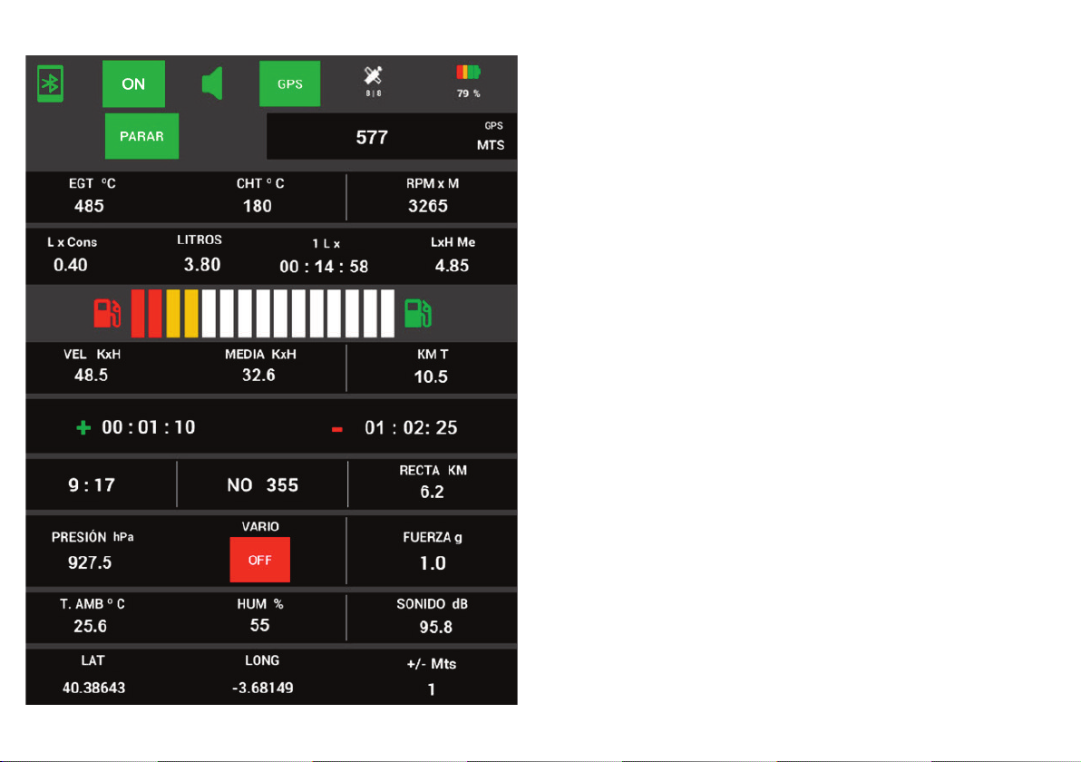
62 - Manual - Home Screen
63 - Manual - English Screen
63 - Meter Screen - GPS FREE
65 - English Parts - General
66 - Part - General - SOS
70 - Part - General - Totals
76 - Part - General - Data
82 - Part - General - Routes
84 - Part - General - User
87 - Part - General - Messages
90 - Part - General - Conditions
102 - Part - Extras - Consump-
tion
103 - Part - Extras - Shooting
112 - Part - Extras - Converter
113 - Part - Extras - Compass
114 - Versions Download
115 - Links Videos

When you purchase, the PXP Meter includes:
1 - 1 Protective and organization Briefcase.
2- 1 Switchboard with VGA connection.
3- 1 VGA sensor connections + cables + watertight sensor connections.
4- 1 Fuel Sensor + cable + three-pin watertight connection.
5- 1 Pressure, temperature and humidity Sensor + cable + four-pin watertight connection.
6- 1 EGT temperature sensor + nut to solder the exhaust + cover screw + cable + 2 pin
watertight with yellow connection.
7- (only if you have purchased the version CHT) 1 CHT temperature Sensor (14 mm) +
cable + 2-pin watertight with green connection (see other spark plugging measurements).
8- (only if you have purchased H2O version) 1-H2O temperature Sensor + cable + 2 pin
watertight with blue connection (see options for pipe connection measures)
9- Revolution Counter Sensor + cable + 1 pin watertight with red connection.
10 - Ground Cable + terminals + 1 pin watertight with black connection.
11 - Connectors + 3 Cable connections to a 12 V external battery + terminals.
12 - 2x screw clamps with plastic from 12/14/16 mm each, screws for clamps, flanges, va-
rious heat shrinks, a cordura cover for cables and several ones for the correct assembly.
13 - Installation and operation manual.
4

What type of Battery does the PXP Meter use?
The PXP Meter is powered by a 12
volt battery.
You can use different types of batteries:
1 -We supply a battery (optional, you can buy
separately): Rechargeable lithium USB Battery
(Li-Ion) from 5v to 5600mAh, another from
12v to 3800mAh, also with USB + 12 volt out-
put + switcher + LED status charge + charger.
We provide you with the serial cable and con-
nection terminal. Measures: 95 x 60 x 20 mm
(recommended small and practical).
2-You can have power in your engine (for
example if you have an electric starter).
We provide you with the serial cable and con-
nection terminals.
3-You can use a type of battery car starter of
the latest generation with different types of
capacities.
We provide you with the serial cable and con-
nection terminal. (See next page).
Battery offered by PXP Paramotor
5

You have to keep in mind that the biggest the heaviest
it is and this can make it difficult to install it for exam-
ple if we are going to use the PXP meter in flight with
Paramotor, but it is neither a big problem.
We are going to supply you with from the series de-
pending on the battery chosen all the connectors and
connection cables, you will find everything prepared
for the connection and power of the PXP Meter.
How to buy the latest generation of car battery starter?
You can search on Google: car battery starter or battery starter
or search on Amazon = car battery starter.
You will find hundreds of offers, if you're only going to use it
for the PXP meter, we recommend you to buy the smallest
(6000-8000 mAh, that usually cost between about €25-45, but
there are more expensive) as we have told you the PXP Meter
does not consume much electricity.
Well if you prefer this battery starter is very interesting also to
carry it in the car, caravan, etc or used to charge the mobile or
tablet, you have flash light and other 1000 uses, you can buy
a bigger one.
6

1 - Supplied connectors and cables
3 - Battery installation
-small Starter
2 - Installation with Battery PXP Meter
3 - Battery installation
-great starter
7

Simple Manual
1-Install the switchboard.
2-Install the sensors.
3-Connect the sensors with the switchboard.
4-Download the PXP Meter App.
5-Install the PXP Meter App
6-Connect the battery to the switchboard.
7-Match the Bluetooth.
8-Go on the screen of the PXP Meter App.
9-Connect the Bluetooth.
10 -Configure the PXP Meter App.
Although you see a long and ex-
tensive Manual, do not confuse
the PXP Meter is very easy to as-
semble, set up and work with.
We've just put everything very
detailed.
You will do with it at the moment
of use and you will not find any
problem.
We have already been responsi-
ble for everything to work at
100%.
8
““The PXP Meter is ready to work and
offer you all the data for hours and
hours, without rest."”

Installation of the Switchboard
The installation of the Switchboard is very simple.
We will supply as standard: 6 screw clamps with plastic protection 12mm / 14mm / 16mm
x 2 of each (other sizes on request), 2 screws of 6mm x 20mm and 2 velcro straps + battery
fasteners.
With these clamps and the threads installed in the Control Unit, we will be able to install our
Control Unit in any position we wish.
Let's give a practical example of mounting on a Paramotor.
Depending on whether we need to disassemble the Paramotor chassis we can choose one
place or another, however we recommend installing it in a fixed place (away from the fuel
tank inlet or the engine exhaust = heat) and that does not affect the assembly or disassembly
of the Paramotor chassis and so we have our Control Unit always fixed, much better.
Clamps + screws
and threads Switchboard NOT about input fuel NOT by engine exhaust
9

4 - We focus and tighten
screws in threads Battery 5 - Paste Battery velcro 6 - We set Battery with
tape and velcro
1 - We chose site to install 2 - Check measurement tube 3 - We introduce
clamps + Velcro
10

Installing the Sensors
1 - Installation "Fuel Sensor" (3 Pins)
It is very easy to cut the tube that supplies the fuel to the engine, (be careful if you have
fuel, dry well or blow before warming up) we heat a little to make it more flexible and insert
both sides of the sensor into the tube.
1 - We cut pipe 3 - We set with clips
and we assure
2 - We see direction arrow e
introduce both sides
Note: if we see the Sensor has position, we have to see
the arrow and install and respect this position of direction
of fuel inlet, otherwise it does not work.
11

2 - Installation "Speed Sensor - RPM" (1 Pin - Red)
It is very easy to wind the red wire onto the coil cable, fix it with the supplied clips and you
are ready to go.
1 - Wrapped red wire on coil wire 2 - Tighten and secure with clips
12

3 - Installation "Pressure, Temperature and Humidity Sensor" (4 Pins)
The only thing we have to do is to install this sensor in a position that can be seen (so that
it can mark the temperature and humidity well, if it is hidden because it can give us lower
values, little thing) and to take into account that if for example we use the PXP Meter in flight
in Paramotor and this is removable, because in a place that does not bother us when assem-
bling and disassembling, that is visible and always remains fixed.
We will fix it with the clips - flanges supplied and ready.
1 - Put on visible site 2 - We set with clips and ensure
13

4 - Installation "CHT Sensor" (2 Pins - Green)
It is very easy to unscrew the spark plug, insert the round of the sensor and screw the spark
plug back in, very easy.
As standard we will supply the round of the sensor in 14 mm but we have measures of 10 /
12 mm.
1 - Remove spark plug + get
round Sensor 3 - Completed2 - Tighten spark plug
Note: we will take into account that the cable that comes out of the round of the
Sensor does not touch much with the aluminum of the cylinder head, it can burn
and break the Sensor with the vibrations, we leave the most centered and clean as
possible.
14

5 - Installation "Sensor EGT" (2 Pins - Yellow)
Perhaps it is the most complicated sensor to install, because we have to weld the nut that
will hold the sensor in the engine exhaust.
But it will be worth it because the EGT temperature is one of the most important data because
it tells us if our engine is well carbonated and the air-fuel mixture has the right ratio (rich
mixture: for having excess fuel or lean mixture: for having lack of fuel).
" Probably the most important data to have in an engine "
1- The first thing we do is tap and drill a 5mm hole in the exhaust, as close as we can to
the cylinder outlet with the exhaust.
Recommended for forward-facing sides - pilot side, "never stop the propeller".
If we see that with the exhaust mounted we have difficulty, then we dismount the exhaust
for the operation. (Recommended) If we do not disassemble the exhaust, after drilling, move
it and turn it downwards in case we have any chips in the exhaust).
2- Clean paint, prepare for welding.
3- We are going to prepare - thread the sensor into the nut supplied as standard.
4- We will regulate the length of the sensor that does not give us in the other part of the
exhaust, more or less that it is a little longer from the center, but without touching the other
side. We're pushing a little bit for regulation right now. We introduce and test.
15

5- We introduce the sensor with the nut in the 5 mm hole, straighten it, find the perfect po-
sition and give some welding points to the nut to fix it.
6- Once the nut has been fixed and punched, unscrew the sensor and thread the screw so
that it does not deform the nut during welding and weld the nut. Be careful not to get too
hot and make holes in the exhaust. (Recommended for professional welding and Tig wel-
ding).
7- Once welded the nut, we remove the screw and we can paint with antirust paint now
that it is hot from the weld and leave better finish, each one to your liking.
8- Mount the exhaust if it was dismounted to carry out the operation.
9- Wait for it to cool down and mount the sensor, checking that it is not giving readings for
another part of the exhaust and tightening the sensor to the exhaust and 2 of the sensor
(counter-thread) so that it is well fixed and with perfect adjustment.
N.B. You must check that the tightening of the counter-thread and the tightening
of the sensor to the exhaust will have to be done when the engine is cold and tigh-
ten if necessary, if it becomes loose with the vibrations this could break the sensor
cables. Always check this tightness.
10 - It is now installed and finished.
16

1 - Make brand 2 - Clean paint1.1 - Drill hole 5 mm
3 - Prepare Sensor
with nut 5 - Tap the nut4 - Regular long + focus
17

7 - Paint and finish 9 - Regular length
+ Press Sensor 9 - Tighten the two nuts
6 - Dotted nut
+ Remove Sensor 6 - Put screw 6 - Weld nut
18

6 - Installation “H2O Sensor” (2 Pins - Blue)
1- Firstly get the cooling tube suitable for the installation of the sensor.
2- Check that the thickness of the sensor (ordered beforehand) corresponds to the thickness
of the tube to be installed, as it will have to be cut, and if it is cut and the tube does not co-
rrespond to the right thickness (too large or too small) this will make work. So make sure.
3- If there is water or antifreeze in the circuit we will have to prepare this as we will have
to cut the tube, and liquid will leak and stain. It is recommended to empty the circuit of
water or antifreeze before cutting the tube to below the level of where we are going to cut
the tube. You decide.
4- Cut the tube.
5- Place the clamps one each side of the tube.
6- Installation – insert the sensor, one each side (if there is difficulty heat the tube and per-
haps use a little multiuse lubricant oil to facilitate the entry).
7- Tighten the clamps. Screw the other part of the sensor with the cable.
8- Fill and check the water level or antifreeze.
9 - We have it installed and finished.
19

1 - Cut pipe 2 - Insert Sensor in tube 3 - Tighten clamps + screw
Sensor cable
"REMEMBER" Fill and check the water level or antifreeze.
7 - Installation "Ground Cable" (1 Pin - Black).
We are going to install the ground cable to any affordable
screw of the motor, we provide you with 1 terminal of 6 m.m
and another of 8 m.m. Choose the screw according to 6 m.m
or 8 m.m, insert into the heat shrink before assembling the
terminal, close the terminal, adjust and heat the shrink, ins-
tall and tighten the chosen screw with the ground cable ter-
minal.
20
Table of contents
Popular Accessories manuals by other brands

Spectech
Spectech T154 user manual

Climax Technology
Climax Technology LM-1ZW quick start guide

Bircher Reglomat
Bircher Reglomat Reflex motion 2 user guide

Vinotemp
Vinotemp WINE-MATE WM-2500SSR Operation Care Installation Manual

Baumer
Baumer FEDK 07N6901/KS35A manual

PCB Piezotronics
PCB Piezotronics IMI SENSORS 518QHBZ Installation and operating manual