Enertex ProxyTouch KNX Quick guide


2018-04-11 Page 2 of 18
Note
The contents of this document may not be wholly or partially, reproduced, transferred,
distributed or stored in any form without prior written approval by Enertex® Bayern GmbH.
Enertex® is a registered trademark of Enertex® Bayern GmbH. Other product- and company
names mentioned herein can be names of trademark or registered trademarks of their
respective owners.
This manual may be changed without notifications or notice and makes no claim to
completeness or accuracy.
Contents
Notes.............................................................................................................................................................. 2
Help function................................................................................................................................................. 2
Overview........................................................................................................................................................ 3
Co issioning............................................................................................................................................ 3
Supply....................................................................................................................................................... 3
Connection diagram................................................................................................................................. 4
Application................................................................................................................................................ 4
Fitting & installing instructions..................................................................................................................5
Default -
no waterproofing required........................................................................................................................5
ith waterproofing -
e.g. in showers......................................................................................................................................... 7
Software description....................................................................................................................................8
Programming............................................................................................................................................ 8
Button partitioning.................................................................................................................................... 8
Lock object............................................................................................................................................... 9
Specification............................................................................................................................................. 9
ETS Application - Para eter....................................................................................................................... 9
General.....................................................................................................................................................................
Buttons...................................................................................................................................................................10
Configuration of buttons.........................................................................................................................................10
Group objects.........................................................................................................................................................11
Revision History......................................................................................................................................... 18
Notes
•Installation and mounting of electrical equipment must be carried out by qualified
electricians. Please note here the section Fitting & installing instructions.
•When connecting KNX/EIB devices specialist skills provided by KNX™ trainings are
required.
•Ignoring the instructions can damage the device, as well a fire or other hazards can
arise.
•These instructions are part of the product and must be left with the end user.
•The manufacturer is not liable for costs or damages incurred by the user or third parties
through the use of the device, misuse or malfunction of the connection, malfunction of
the device or user equipment.
•Opening the housing, other unauthorized alterations and or modifications to the device
will invalidate the warranty!
•The manufacturer is not liable for improper use.
•During installation, pay attention to maintenance access. Claims for damages for
consequential damages due to removing is not granted and is excluded.
Help function
This pdf document uses the division into sections of the Acrobat Reader, which are also called
as “bookmark”. Click on the left edge on the bookmarks tab to view this.
Enertex® Bayern GmbH – Ebermannstädter Straße 8 - 1301 Forchheim - Deutschland - mail@enertex.de

2018-04-11 Page 3 of 18
Overview
The Enertex®-ProxyTouch KNX is a capacitive touch sensor that can be installed behind
surfaces such as ceramic, wood and glass. It has three sensor areas (see Figure 7) that can be
flexibly adapted to the preferences of the user:
Basic features
•The sensors can be addressed together,
•individually,
•or by slide gestures.
•For individual sensors also a double click is applicable for each sensor area.
•If the slide gesture is set, the 3 sensor areas can be additionally addressed by a double
click and as a single common button.
Feedback
If you touch the tile, behind which the device was mounted, at the desired sensor area (A, B or
C), so a message is written to the bus. After contact (parametrizable) an audible feedback is
given, which at each panel has a different pitch (A=high, B=medium, C=low). If the back of the
device is available, a light up of orange LEDs below the respective sensor area can be seen
when touching the control panel. If the device is in programming mode, a red LED is visible and
an acoustic signal is given. The volume of the acoustic signal can be changed in three stages.
Cleaning operation
In the device a cleaning operation mode can be activated via the group object (KNX message).
When this is active and an operation/trigger of the sensors is done by the user, so no messages
are triggered and parametrizable an acoustic signal is generated. The cleaning operation mode
can be canceled by itself parametrized via a time constant up to max. 3h.
Application
Since the sensors react to changes in the surrounding electric field, the functionality of the
ProxyTouch KNX is better given at a rapid approach than at a slow. In addition, the surface of
the material has to be really touched to excite the sensor. Wiping or approaching without contact
does not lead to tripping. By using double click it has to be ensured that the complete gesture
was really led away from the sensor and back to it again. A simple quick tap with your finger, as
usual from the computer mouse operation, is not sufficient.
Co issioning
Supply
For the operation of the Enertex® ProxyTouch KNX an external voltage supply is not needed.
The device gets the supply voltage from the bus.
Enertex® Bayern GmbH – Ebermannstädter Straße 8 - 1301 Forchheim - Deutschland - mail@enertex.de
2018-04-11 Page 4 of 18
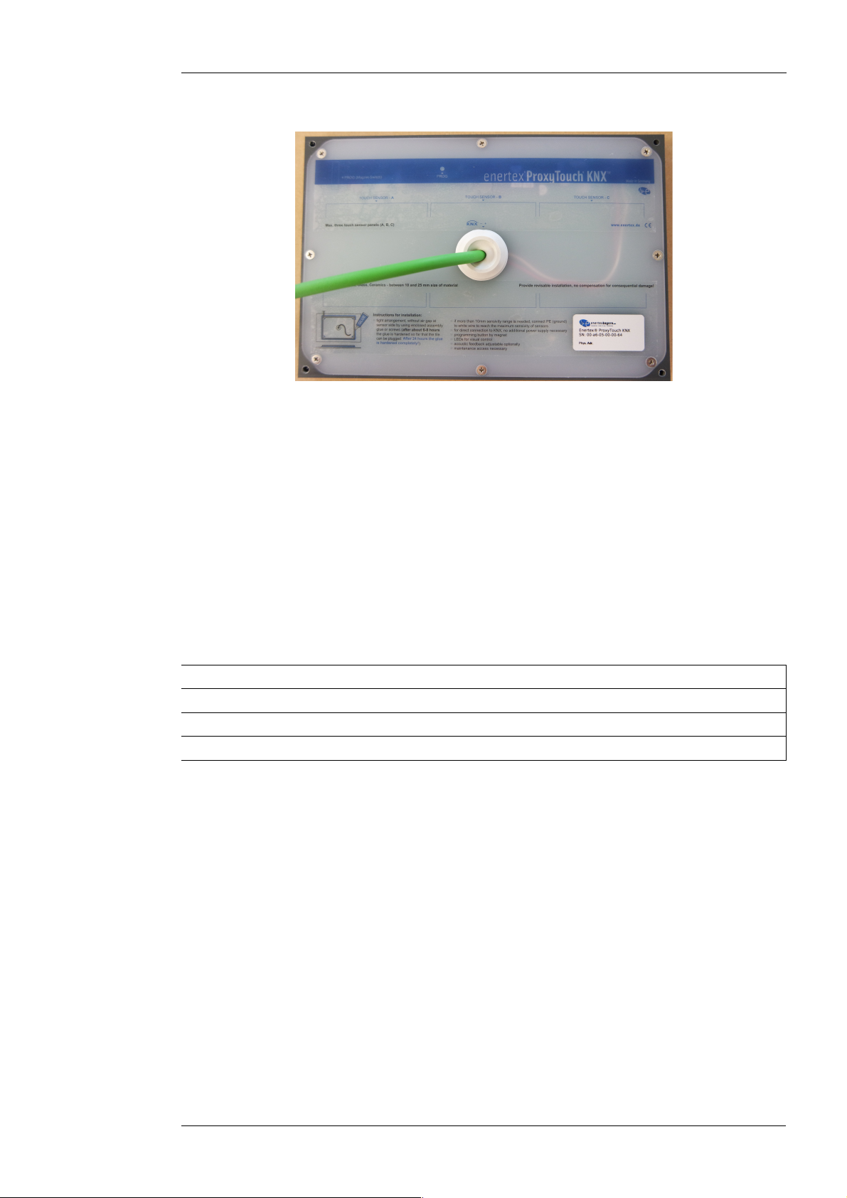
Connection diagra
Figure 1: Connections Front view
•Before installing the ProxyTouch in the wall the KNX cable must be connected to the
KNX bus.
•Especially in case of an installation behind thicker wall coverings the white conductor in
the KNX connection cable of the sensor may be connected to the protective earth of the
building to increase the sensitivity. Thereby, the KNX bus is capacitively coupled to the
protective earth.
•The magnetic switch button at the bottom right sets the ProxyTouch into the
programming mode.
Application
The Enertex® ProxyTouch KNX can be mounted behind several materials with different
thicknesses.
Material Max. reco ended aterial thickness
Tile 25 mm
Wood 20 mm
Glass 25 mm
To ensure the functionality completely, the maximum material thicknesses must be noted. It may
be also necessary to connect the white conductor in the KNX connection cable of the sensor to
the protective ground of the building. Thereby, the KNX bus is capacitively coupled to the
protective earth.
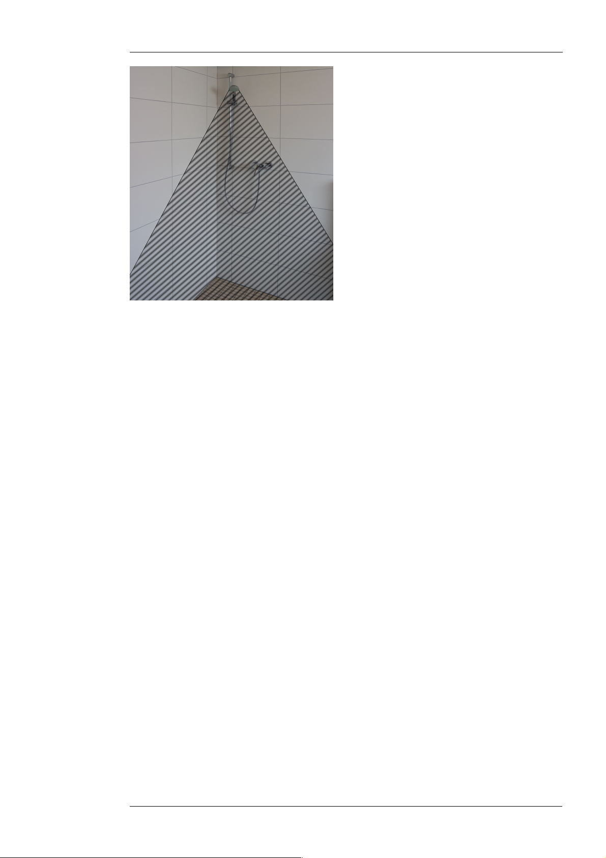
The Enertex®-ProxyTouch can be installed in wet rooms. Direct water jet is to be avoided. It is
recommended that the mounting position in wet rooms is so configured that splash from the
biggest person hits the sensors as little as possible. In the next Figure 2, the shower head is at
height of 1. 5 meters, thus the striped area due to the angle of radiation is not recommended
for mounting:
Enertex® Bayern GmbH – Ebermannstädter Straße 8 - 1301 Forchheim - Deutschland - mail@enertex.de
2018-04-11 Page 5 of 18
Figure 2: Installing position in wet rooms
The robustness of the ProxyTouch decreases with increasing water amount reacting on the
surface. In contrast to the direct reaction of a water jet, low splashing and water vapor do not
result to false tripping. The robustness of the ProxyTouch is substantially increased when in wet
rooms the button partitioning “Slide gestures” is applied and the sensor areas are only
configured as double click.
At this point it is again referenced to the application described above:
Since the sensors react to changes in the surrounding electric field, the functionality of the
ProxyTouch is better at a rapid approach than at a slow. Furthermore the surface of the material
has to be really touched to excite the sensor. Wiping without contact does not lead to tripping. At
double click it has to be ensured that the complete gesture was led away from the sensor and
back to it again. A simple quick tap with your finger, as usual from the computer mouse
operation, is not sufficient.
Fitting & installing instructions
A correct installation is fundamental for Enertex® ProxyTouch KNX to work as designed, and
depends on its operation area. It must also be ensured that the ProxyTouch KNX lies as flat as
possible on the back, that is it should be avoided, that an “air” distance is formed between the
back of the desired surface and the ProxyTouch KNX. A possible distance between the
mounting material and the sensor reduce the sensor range. In particular, “air” between the two
dampens the range by factor by factor 3 to 4 which means that 2mm air between sensor and
back side of mounting location corresponds to a 6 to 8 mm range shortening.
During installation, pay attention to aintenance access. Clai s for da ages for
consequential da ages due to dis ounting is not granted and is excluded.
Default -
No waterproofing
The Enertex® ProxyTouch KNX is each aligned and fixed on the back of the desired surface. In
case of tiles, plastic and glass the housing is glued to the edges using the enclosed adhesive.
For wood the housing has additional holes at the corners, through which the housing can be
screwed together with screws. With the use of the mounting adhesive the housing must be
placed and fixed on the intended place of the material to prevent slippage during the bonding
operation (Figure 3). It must be ensured that the adhesive surface is clean, dry and free of dust
and grease.
Enertex® Bayern GmbH – Ebermannstädter Straße 8 - 1301 Forchheim - Deutschland - mail@enertex.de

2018-04-11 Page 6 of 18
Figure 3: Fixing the housing
If so, the mounting adhesive can laterally be applied 5mm high in the corner between housing
and material.
Figure 4: Applying the adhesive mounting
To obtain a clean glue line, the applied mounting adhesive is spread.
Figure 5: Spreading the mounting adhesive
After the three easily accessible sides have been glued, the fixing can be untightened and the
last side can be bonded. While curing, the mounting should be weighted down to ensure a very
dense contact pressure at the surface. After about 6-8 hours the adhesive is so far cured that
the tile can be plugged. After 24 hours the adhesive is fully cured.
Enertex® Bayern GmbH – Ebermannstädter Straße 8 - 1301 Forchheim - Deutschland - mail@enertex.de
2018-04-11 Page 7 of 18
With waterproofing -
e.g. in showers
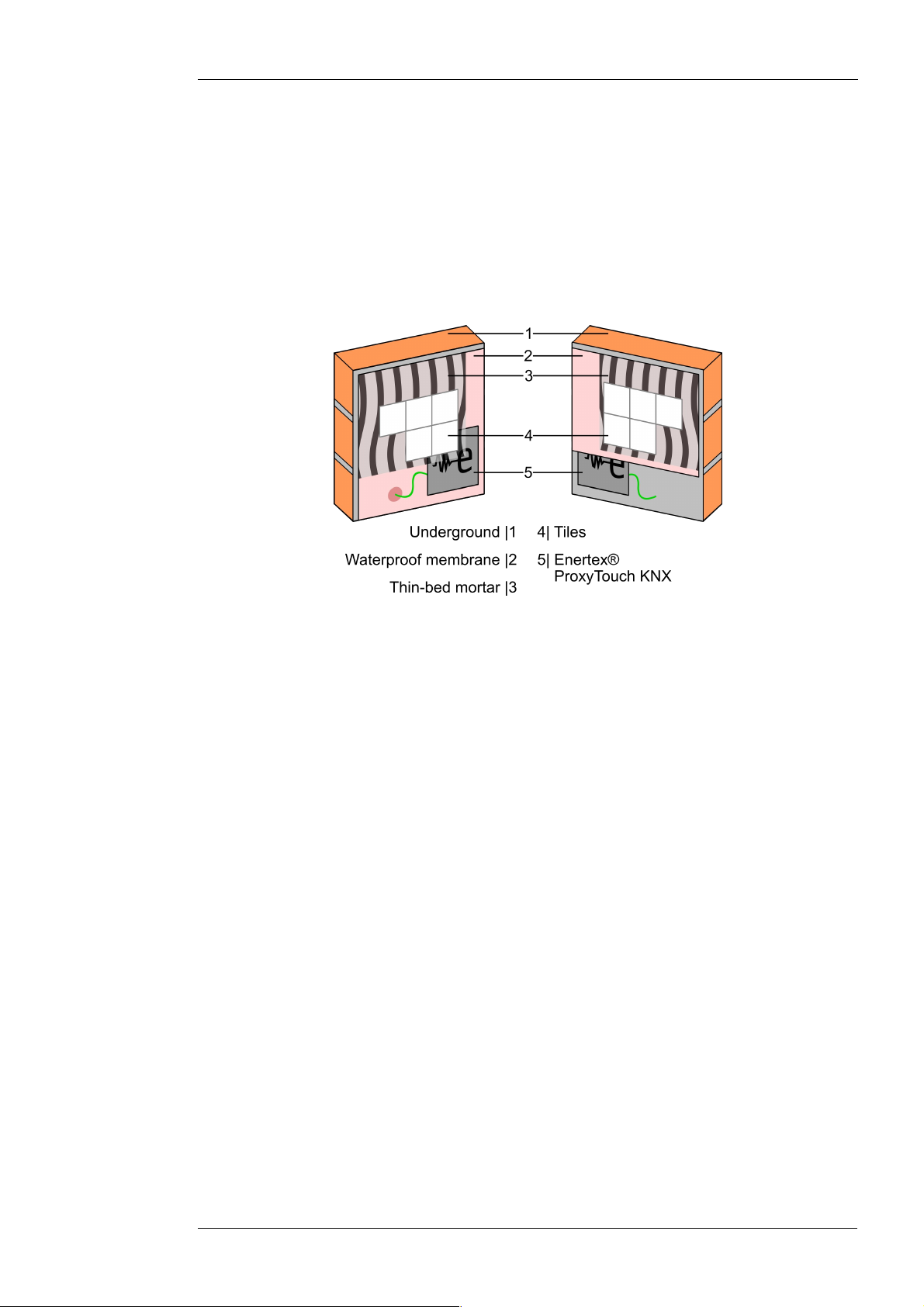
If the operation area is regularily exposed to water, waterproofing may be required. Please
consult IBC chapter 27 or Tile Council of North America (TCNA) publications, e.g., TCNA
Handbook for Ceramic, Glass, and Stone Tile Installation for detailed instructions. To maintain a
waterproof sealing of the underground construction, Figure 6 recommends two installation
options. The ProxyTouch KNX may be installed on or below the waterproof membrane. It
depends on the detailed conditions, which one is better suited. Please note the recommended
material thicknesses mentioned above is 25mm for tiles.
Figure 6: Waterproof installation
Enertex® Bayern GmbH – Ebermannstädter Straße 8 - 1301 Forchheim - Deutschland - mail@enertex.de

2018-04-11 Page 8 of 18
Software description
Progra ing
The device is programmed via the ETS. By the enclosed magnet the device can be set, even
after installation, into the programming mode. For this purpose the magnet is swept over the
surface behind which the device is located. The activation switch is located in the upper left
corner of the device and thus in the upper right corner of the surface. Once the device is in
programming mode an audible signal (buzz) can be clearly heard. If the device has not yet been
installed, a visual feedback (red LED) is also visible besides the audible signal.
Button partitioning
According to the parameterization up to four different messages can be transmitted to the KNX
bus via the touch panels. Each panel gives an audible feedback when touched. Thereby the
sound output varies from high (A) to deep (C). In the button partitioning “Slide gestures” and the
function double click an even higher tone than in single button is emitted in case of successful
operation.
The panel is divided into a maximum of three different sensor areas:
Figure 7: Panels Front view
By para etrization in the ETS the following button partitionings are available:
•Merged buttons
Here, the three sensor areas (A, B, C) are combined to form a one large panel. To carry
out the action programmed in the ETS, touch by hand the surface, behind which the
Enertex®-ProxyTouch is located.
•Single buttons
Here, each sensor area (A, B, C) represents a a control panel. To carry out the action
programmed in the ETS, touch by hand the point on the surface, behind which the
corresponding control panel is located. For all sensor areas a double click is possible.
The double click is triggered by two quick consecutive touches.
•Slide gestures
Here the slide gesture is assembled by the sensor areas (A→C) and (C→A). To carry
out the action programmed in the ETS, sweep with the open hand over the surface,
behind which the Enertex®-ProxyTouch is located. To detect a slide gesture the hand
movement must not be too slow. The sensor areas have two button functions, wherein
for all sensor areas a common single button and a double click is possible. The double
Enertex® Bayern GmbH – Ebermannstädter Straße 8 - 1301 Forchheim - Deutschland - mail@enertex.de

2018-04-11 Page of 18
click is triggered by 2 quick consecutive touches.
Lock object
In each button partitioning the object function Lock object is available. With this object it is
possible to lock the sensor areas whereby no action can be carried out any more. This is
important for example for the cleaning operation to prevent unwanted triggering. If the object has
been set, it can be heard by an audible signal (buzz) during operation of the sensor.
Specification
ETS: from version 3.0d, patch A
ETS Application - Para eter
Note: Depending on the configuration some settings may not be available. They are not shown
in the ETS in these cases.
General
Under the tab “General” the following settings can be made:
Figure 8: General settings
Description of the para eters:
Enertex® Bayern GmbH – Ebermannstädter Straße 8 - 1301 Forchheim - Deutschland - mail@enertex.de
2018-04-11 Page 10 of 18
Na e Options Description
Acoustic feedback Off
Function
Key lock
Function/key lock
Mode in which an acoustic feedback
is given.
Volume 1 / 2 / 3 Volume of the audible feedback from
1 (low) to 3 (high)
Unlock keys after 5 min
10 min
15 min
...
3 h
-
Time, after which the key lock is to
be automatically turned off.
“-”=key lock is not turned off
automatically
Buttons
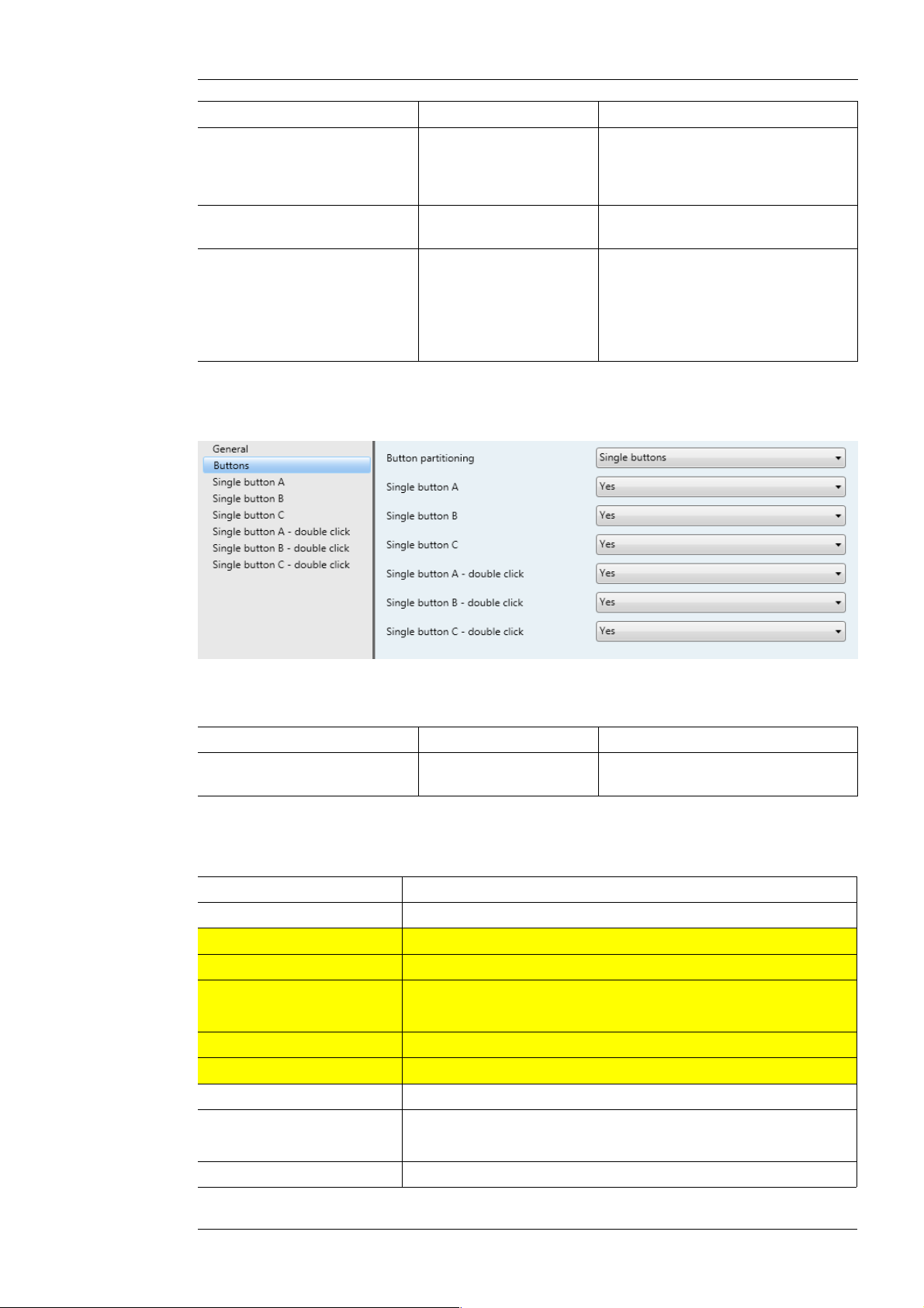
Under the tab “Buttons” the following settings can be made:
Figure 9: Parameter Buttons
Description of the parameters:
Na e Options Description
Button partitioning Merged buttons / Single
buttons / Slide gestures
setting of the panels
Configuration of buttons
Description of the parameters:
Na e Options
Merged buttons Switch / Dim / Blinds / Start scene / Percentage
Single button A Switch / Dim / Blinds / Start scene / Percentage
Single button B Switch / Dim / Blinds / Start scene / Percentage
Single button C Switch / Dim / Blinds / Start scene / Percentage
Double click A Switch / Dim / Blinds / Start scene / Percentage
Double click B Switch / Dim / Blinds / Start scene / Percentage
Double click C Switch / Dim / Blinds / Start scene / Percentage
Slide gesture A→C Switch / Dim / Blinds / Start scene / Percentage
Slide gesture C→A Switch / Dim / Blinds / Start scene / Percentage
Single button Switch / Dim / Blinds / Start scene / Percentage
Double click A Switch / Dim / Blinds / Start scene / Percentage
Enertex® Bayern GmbH – Ebermannstädter Straße 8 - 1301 Forchheim - Deutschland - mail@enertex.de

2018-04-11 Page 11 of 18
Double click B Switch / Dim / Blinds / Start scene / Percentage
Double click C Switch / Dim / Blinds / Start scene / Percentage
1st order 2nd order 3rd order Options Description
Switch Value 0 / 1 / Toggle Value which is
transmitted on the bus
Dim Dim (relatively) Action Decreasing / Increasing Decreases or
increases to set stage
Step 0 - 7 0 = no change / 1 =
100 % / 2 = 50 % / 3 =
25 % / 4 = 12 % / 5 = 6
% / 6 = 3 % / 7 = 1 %
Switch Value 0 / 1 / Toggle Value to be transmitted
on the bus.
Brightness Percentage 0 – 255 Percentage which is
written on the bus
Blinds Up/down - up Blinds move upwards
Up/down - down Blinds move
downwards
Step - increase/
STOP
Adjustment of the slat
or stop the blind
Step - decrease/
STOP
Adjustment of the slat
or stop the blind
Position Percentage 0 - 255 Blinds move to the
selected percentage
Start scene Scene number 1 – 64 Enables the scene with
the specified number
Percentage Percentage 0 – 255 Percentage is written
on the bus.
Group objects
Notes:
•Depending on the configuration some objects may not be available.
List of data point types (DPTs)
Typ Name Length Description Value
[1.1] DPT_Switch 1 Bit Switching 1, 0
[1.3] DPT_Enable 1 Bit Switching 1, 0
[1.7] DPT_Step 1 Bit Switching 1, 0
[1.8] DPT_UpDown 1 Bit Switching 1, 0
[3.7] DPT_Control_Dimming 4 Bit Relatively Dimming 0 = Stop
1 = 100 %
2 = 50 %
3 = 25 %
4 = 12 %
5 = 6 %
6 = 3 %
7 = 1 %
Enertex® Bayern GmbH – Ebermannstädter Straße 8 - 1301 Forchheim - Deutschland - mail@enertex.de

2018-04-11 Page 12 of 18
[5.1] DPT_Scaling 1 Byte Value Percentage
0% = 0......255 = 100%
[18.1] DPT_SceneControl 1 Byte Calling scene 0......63
ID Name Object function Length Type Flags
0 General Lock object 1 Bit [1.3]
DPT_Enable
RWCT--
ID Name Object function Length Type Flags
1 Merged buttons Switch 1 Bit [1.1]
DPT_Switch
--CT--
ID Name Object function Length Type Flags
2 Merged buttons Dimmer 4 Bit [3.7]
DPT_Control_Dimm
ing
--CT--
ID Name Object function Length Type Flags
3 Merged buttons Percentage 1 Byte [5.1]
DPT_Scaling
--CT--
ID Name Object function Length Type Flags
4 Merged buttons Scene 1 Byte [18.001]
DPT_SceneControl
--CT--
ID Name Object function Length Type Flags
5 Merged buttons Up/down 1 Bit [1.8]
DPT_UpDown
--CT--
ID Name Object function Length Type Flags
6 Merged buttons Step 1 Bit [1.007]
DPT_Step
--CT--
ID Name Object function Length Type Flags
7 Single button A Switch 1 Bit [1.1]
DPT_Switch
--CT--
ID Name Object function Length Type Flags
8 Single button A Dimmer 4 Bit [3.7]
DPT_Control_Dimm
ing
--CT--
ID Name Object function Length Type Flags
Single button A Percentage 1 Byte [5.1]
DPT_Scaling
--CT--
ID Name Object function Length Type Flags
10 Single button A Scene 1 Byte [18.001]
DPT_SceneControl
--CT--
ID Name Object function Length Type Flags
11 Single button A Up/down 1 Bit [1.8]
DPT_UpDown
--CT--
ID Name Object function Length Type Flags
12 Single button A Step 1 Bit [1.007]
DPT_Step
--CT--
Enertex® Bayern GmbH – Ebermannstädter Straße 8 - 1301 Forchheim - Deutschland - mail@enertex.de

2018-04-11 Page 13 of 18
ID Name Object function Length Type Flags
13 Single button B Switch 1 Bit [1.1]
DPT_Switch
--CT--
ID Name Object function Length Type Flags
14 Single button B Dimmer 4 Bit [3.7]
DPT_Control_Dimm
ing
--CT--
ID Name Object function Length Type Flags
15 Single button B Percentage 1 Byte [5.1]
DPT_Scaling
--CT--
ID Name Object function Length Type Flags
16 Single button B Scene 1 Byte [18.001]
DPT_SceneControl
--CT--
ID Name Object function Length Type Flags
17 Single button B Up/down 1 Bit [1.8]
DPT_UpDown
--CT--
ID Name Object function Length Type Flags
18 Single button B Step 1 Bit [1.007]
DPT_Step
--CT--
ID Name Object function Length Type Flags
1 Single button C Switch 1 Bit [1.1]
DPT_Switch
--CT--
ID Name Object function Length Type Flags
20 Single button C Dimmer 4 Bit [3.7]
DPT_Control_Dimm
ing
--CT--
ID Name Object function Length Type Flags
21 Single button C Percentage 1 Byte [5.1]
DPT_Scaling
--CT--
ID Name Object function Length Type Flags
22 Single button C Scene 1 Byte [18.001]
DPT_SceneControl
--CT--
ID Name Object function Length Type Flags
23 Single button C Up/down 1 Bit [1.8]
DPT_UpDown
--CT--
ID Name Object function Length Type Flags
24 Single button C Step 1 Bit [1.007]
DPT_Step
--CT--
ID Name Object function Length Type Flags
25 Slide gesture
from A to C
Switch 1 Bit [1.1]
DPT_Switch
--CT--
ID Name Object function Length Type Flags
26 Slide gesture
from A to C
Dimmer 4 Bit [3.7]
DPT_Control_Dimm
ing
--CT--
Enertex® Bayern GmbH – Ebermannstädter Straße 8 - 1301 Forchheim - Deutschland - mail@enertex.de
2018-04-11 Page 14 of 18
ID Name Object function Length Type Flags
27 Slide gesture
from A to C
Percentage 1 Byte [5.1]
DPT_Scaling
--CT--
ID Name Object function Length Type Flags
28 Slide gesture
from A to C
Scene 1 Byte [18.001]
DPT_SceneControl
--CT--
ID Name Object function Length Type Flags
2 Slide gesture
from A to C
Up/down 1 Bit [1.8]
DPT_UpDown
--CT--
ID Name Object function Length Type Flags
30 Slide gesture
from A to C
Step 1 Bit [1.007]
DPT_Step
--CT--
ID Name Object function Length Type Flags
31 Slide gesture
from C to A
Switch 1 Bit [1.1]
DPT_Switch
--CT--
ID Name Object function Length Type Flags
32 Slide gesture
from C to A
Dimmer 4 Bit [3.7]
DPT_Control_Dimm
ing
--CT--
ID Name Object function Length Type Flags
33 Slide gesture
from C to A
Percentage 1 Byte [5.1]
DPT_Scaling
--CT--
ID Name Object function Length Type Flags
34 Slide gesture
from C to A
Scene 1 Byte [18.001]
DPT_SceneControl
--CT--
ID Name Object function Length Type Flags
35 Slide gesture
from C to A
Up/down 1 Bit [1.8]
DPT_UpDown
--CT--
ID Name Object function Length Type Flags
36 Slide gesture
from C to A
Step 1 Bit [1.007]
DPT_Step
--CT--
ID Name Object function Length Type Flags
37 Slide gesture
double click B
Switch 1 Bit [1.1]
DPT_Switch
--CT--
ID Name Object function Length Type Flags
38 Slide gesture
double click B
Dimmer 4 Bit [3.7]
DPT_Control_Dimm
ing
--CT--
ID Name Object function Length Type Flags
3 Slide gesture
double click B
Percentage 1 Byte [5.1]
DPT_Scaling
--CT--
ID Name Object function Length Type Flags
40 Slide gesture
double click B
Scene 1 Byte [18.001]
DPT_SceneControl
--CT--
Enertex® Bayern GmbH – Ebermannstädter Straße 8 - 1301 Forchheim - Deutschland - mail@enertex.de
2018-04-11 Page 15 of 18
ID Name Object function Length Type Flags
41 Slide gesture
double click B
Up/down 1 Bit [1.8]
DPT_UpDown
--CT--
ID Name Object function Length Type Flags
42 Slide gesture
double click B
Step 1 Bit [1.007]
DPT_Step
--CT--
ID Name Object function Length Type Flags
43 Slide gesture
single button B
Switch 1 Bit [1.1]
DPT_Switch
--CT--
ID Name Object function Length Type Flags
44 Slide gesture
single button B
Dimmer 4 Bit [3.7]
DPT_Control_Dimm
ing
--CT--
ID Name Object function Length Type Flags
45 Slide gesture
single button B
Percentage 1 Byte [5.1]
DPT_Scaling
--CT--
ID Name Object function Length Type Flags
46 Slide gesture
single button B
Scene 1 Byte [18.001]
DPT_SceneControl
--CT--
ID Name Object function Length Type Flags
47 Slide gesture
single button B
Up/down 1 Bit [1.8]
DPT_UpDown
--CT--
ID Name Object function Length Type Flags
48 Slide gesture
Single button B
Step 1 Bit [1.007]
DPT_Step
--CT--
ID Name Object function Length Type Flags
4 Slide gesture
double click A
Switch 1 Bit [1.1]
DPT_Switch
--CT--
ID Name Object function Length Type Flags
50 Slide gesture
double click A
Dimmer 4 Bit [3.7]
DPT_Control_Dimm
ing
--CT--
ID Name Object function Length Type Flags
51 Slide gesture
double click A
Percentage 1 Byte [5.1]
DPT_Scaling
--CT--
ID Name Object function Length Type Flags
52 Slide gesture
double click A
Scene 1 Byte [18.001]
DPT_SceneControl
--CT--
ID Name Object function Length Type Flags
53 Slide gesture
double click A
Up/down 1 Bit [1.8]
DPT_UpDown
--CT--
ID Name Object function Length Type Flags
54 Slide gesture
double click A
Step 1 Bit [1.007]
DPT_Step
--CT--
Enertex® Bayern GmbH – Ebermannstädter Straße 8 - 1301 Forchheim - Deutschland - mail@enertex.de

2018-04-11 Page 16 of 18
ID Name Object function Length Type Flags
55 Slide gesture
double click C
Switch 1 Bit [1.1]
DPT_Switch
--CT--
ID Name Object function Length Type Flags
56 Slide gesture
double click C
Dimmer 4 Bit [3.7]
DPT_Control_Dimm
ing
--CT--
ID Name Object function Length Type Flags
57 Slide gesture
double click C
Percentage 1 Byte [5.1]
DPT_Scaling
--CT--
ID Name Object function Length Type Flags
58 Slide gesture
double click C
Scene 1 Byte [18.001]
DPT_SceneControl
--CT--
ID Name Object function Length Type Flags
5 Slide gesture
double click C
Up/down 1 Bit [1.8]
DPT_UpDown
--CT--
ID Name Object function Length Type Flags
60 Slide gesture
double click C
Step 1 Bit [1.007]
DPT_Step
--CT--
ID Name Object function Length Type Flags
61 Single button
double click A
Switch 1 Bit [1.1]
DPT_Switch
--CT--
ID Name Object function Length Type Flags
62 Single button
double click A
Dimmer 4 Bit [3.7]
DPT_Control_Dimm
ing
--CT--
ID Name Object function Length Type Flags
63 Single button
double click A
Percentage 1 Byte [5.1]
DPT_Scaling
--CT--
ID Name Object function Length Type Flags
64 Single button
double click A
Scene 1 Byte [18.001]
DPT_SceneControl
--CT--
ID Name Object function Length Type Flags
65 Single button
double click A
Up/down 1 Bit [1.8]
DPT_UpDown
--CT--
ID Name Object function Length Type Flags
66 Single button
double click A
Step 1 Bit [1.007]
DPT_Step
--CT--
ID Name Object function Length Type Flags
67 Single button
double click B
Switch 1 Bit [1.1]
DPT_Switch
--CT--
ID Name Object function Length Type Flags
68 Single button
double click B
Dimmer 4 Bit [3.7]
DPT_Control_Dimm
ing
--CT--
Enertex® Bayern GmbH – Ebermannstädter Straße 8 - 1301 Forchheim - Deutschland - mail@enertex.de

2018-04-11 Page 17 of 18
ID Name Object function Length Type Flags
6 Single button
double click B
Percentage 1 Byte [5.1]
DPT_Scaling
--CT--
ID Name Object function Length Type Flags
70 Single button
double click B
Scene 1 Byte [18.001]
DPT_SceneControl
--CT--
ID Name Object function Length Type Flags
71 Single button
double click B
Up/down 1 Bit [1.8]
DPT_UpDown
--CT--
ID Name Object function Length Type Flags
72 Single button
double click B
Step 1 Bit [1.007]
DPT_Step
--CT--
ID Name Object function Length Type Flags
73 Single button
double click C
Switch 1 Bit [1.1]
DPT_Switch
--CT--
ID Name Object function Length Type Flags
74 Single button
double click C
Dimmer 4 Bit [3.7]
DPT_Control_Dimm
ing
--CT--
ID Name Object function Length Type Flags
75 Single button
double click C
Percentage 1 Byte [5.1]
DPT_Scaling
--CT--
ID Name Object function Length Type Flags
76 Single button
double click C
Scene 1 Byte [18.001]
DPT_SceneControl
--CT--
ID Name Object function Length Type Flags
77 Single button
double click C
Up/down 1 Bit [1.8]
DPT_UpDown
--CT--
ID Name Object function Length Type Flags
78 Single button
double click C
Step 1 Bit [1.007]
DPT_Step
--CT--
Communication flags according to the KNX specification with the following functions:
•R = Read: allows to read a value from group object
•W = Write: allows to write to the group object
•C = Communication: bus communication possible
•T = Transmit: allows a transmission of a value (usually indicates this flag the transmitting
GA)
•U = Update: allows to update a group object with any feedback ("listen and synchronize"
- functionality)
Enertex® Bayern GmbH – Ebermannstädter Straße 8 - 1301 Forchheim - Deutschland - mail@enertex.de
Table of contents


