BBC Bircher ExpertSystem XL-CP42A24 Series User manual

1
XL-CP42Ax / XL-CP49Ax / XL-CP74Ax / XL-CP99Ax
Translation of the original manual with assembly and mounting instructions
Intended use
1Safety instructions
2Component overview
ENGLISH
374571F
04/21
• Read these operating instructions thoroughly before putting the device into operation
and keep them for future reference.
• Do not use this product other than for its specied application.
• The assembly, mounting, modication or retrotting of sensors and the commissioning
of pressure-sensitive edges may only be undertaken by persons who have completed
relevant professional training and have been authorised to carry out such work.
• Pay attention to all local relevant electrical safety regulations!
• Failure to follow these safety precautions may cause damage to sensor or objects,
serious personal injury, or death.
• It is the responsibility of the equipment manufacturer to carry out a risk assessment
and to install the system, in compliance with applicable local, national and internatio-
nal regulations, safety standards, codes and laws as well as the Machinery Directive
2006/42/EC, should this apply.
• Always consider the safety functions of your applications as a whole, never just in
relation to one individual section of the system.
• The installer is responsible for testing the system to ensure it meets all applicable
safety standards.
Prior to starting installation or mounting, take the following safety precautions:
• Ensure that the device/installations cannot be switched on!
• Ensure that the power supply is disconnected!
• Cover any neighbouring live parts or remove them!
• Before switching on the power supply, check the wiring as a precaution to prevent
any damage or malfunction affecting the equipment connected to the product.
• If you are leaving the installation site, make sure that the product is working properly
and has been installed correctly. Explain to the building owner/operator the correct
way of operating the industrial door and the product.
Sensor Safety switching
device
Pressure-sensitive edges are pressure-sensitive protection systems.
They are specied in accordance with and meet the requirements of standard
EN ISO 13856-2. Pressure-sensitive edges consist of a sensor and a safety switching
device.
This manual describes the assembly and mounting of sensors of the XL series. These
sensors are active switching proles. They are made from exible rubber and mounted
on metal mounting proles. In accordance with the standard EN ISO 13856-2, the use of
this sensor for pressure-sensitive edges requires the use of a safety switching device
(signal processing and output switching device) specied by BBC Bircher AG and
subjected to the prescribed conformity assessment procedure.
The specications of the various sensor types are listed in their data sheets. These are
to be consulted for the selection of a suitable sensor.
Total length of the assembled sensor = L total
Length of the contact prole and mounting prole:
Total length minus 24 mm
Contact profile
Mounting profile, straight
or
Mounting profile, 20°
Contact end piece
Connection cable
Resistor plug
End cap
End plugs (left / right)
ExpertSystem XL sensors
Open video tutorial here:

2
XL-CP49A30xXL-CP42A24x
XL-CP49A3020x
XL-CP49A36x
XL-CP49A3620x
XL-CP74A30x
XL-CP74A3020x
XL-CP74A36x
XL-CP74A3620x
XL-CP99A36x
XL-CP99A3620x
XL-AP36(Q) XL-AP3620(Q)XL-AP3020(Q)XL-AP30(Q)XL-AP24
42
43 44
3629
37
44
51
60
40
20°
49
48
99
74
74
49
42
49
101
78
78
55
57
20°
49
20°
74
20°
99
20°
74
42
43 44
3629
37
44
51
60
40
20°
49
48
99
74
74
49
42
49
101
78
78
55
57
20°
49
20°
74
20°
99
20°
74
30
13
36
13
32.4
20°
23.6
38
25.7
20°
30
36
24
8
30
13
36
13
32.4
20°
23.6
38
25.7
20°
30
36
24
8
30
13
36
13
32.4
20°
23.6
38
25.7
20°
30
36
24
8
30
13
36
13
32.4
20°
23.6
38
25.7
20°
30
36
24
8
30
13
36
13
32.4
20°
23.6
38
25.7
20°
30
36
24
8
3.2 Delivery format and storage of contact prole components
Mounting proles
Contact prole mounted on mounting proles
XL contact proles are delivered in coils inside sturdy cardboard boxes
on pallets. If they are to be put into long-term storage, the contact
proles must remain inside the boxes and the boxes stored laid at.
Contact end pieces, connection cables and resistor plugs are packaged
separately and must remain inside their original packaging until used.
The components must be stored in a dry location. Storage temperatures
should be between 0°C and 40°C.
However, the components can be stored at temperatures from - 30 °C to
+ 60 °C for short periods of time, e.g. during transport.
3Assembly of ExpertSystem XL sensors
3.1 Sensor types, dimensions
XL sensors can be delivered in a variety of formats.
1. As fully prefabricated sensors in the required length, with or without
quick-fastening system and with cable or integrated XRF-TI radio
transmitter as option – equally suitable for both customer-specic
applications and the series production of industrial doors.
2. As a set in various standard lengths to be cut by the customer and for
self-assembly of a sensor – ideal for repairing doors quickly when
carrying out service and maintenance in the eld.
3. As individual components in larger packaging units – suitable for
self-assembly XL sensors in industrial door manufacture.
The assembly of sensors is described in Chapter 3 below;
their installation is described in Chapter 4.
Contact prole coil
in box

3
✓
✗
1
23
1
3.3 Tools and accessories
L contact prole
= L total
– 24 mm
L total
= total length of the sensor
Rubber prole cutters
“XL-Cut”
Risk of injury!
Follow the safety instructions for
the cutting device.
3.4 Assembly of contact proles
1. Cutting the XL contact prole to length
2. Mounting contact end pieces
Press-in tool
“XL-Ease”
Always cut at right angles
Remove protective plug, if present

4
Ω
4 5
23
3. Intermediate check / Resistance measurement
Connect the resistor plug and the cable, actuate the sensor
at several points
Sensor actuated: ≤ 500 Ω
Sensor not actuated with XL-RP8 resistor plug: resistance between 8.0 and 9.0 kΩ
The sealant should overow all the way round the sealing
edge.
Contact end pieces can only be mounted and used once. Reliable contacting and sealing are not guaranteed during disassembly
and re-assembly!
The sealant is highly adhesive; dust and dirt particles will stick
to it immediately on contact. Therefore, once you have unpacked
a contact end piece and removed the protective cover, you
should proceed with particular care and ensure that the working
environment is kept clean and tidy until it is pressed into place.
Hold the prole shank at an acute angle and check for
axial alignment when pressing the contact end piece in.
Re-attach the protective cover on the side and top of the
sealant on the fully tted contact end piece. (The protective
cover remains under the end cap to be mounted later on.)

5
40 33
53100100
4.1 Cutting the mounting prole to length
4Mounting ExpertSystem XL sensors
Mounting proles, punched, for quick fastening (XL-APxQ)
Mounting proles, solid (XL-APx)
Always cut at right angles
L mounting prole = L total
– 24 mm
6
max.
80 mm
50 mm
12 mm
33 mm
5 mm
max.
80 mm
max.
500 mm
max.
500 mm
max.
500 mm
max.
500 mm
max.
500 mm
max.
500 mm
max.
500 mm
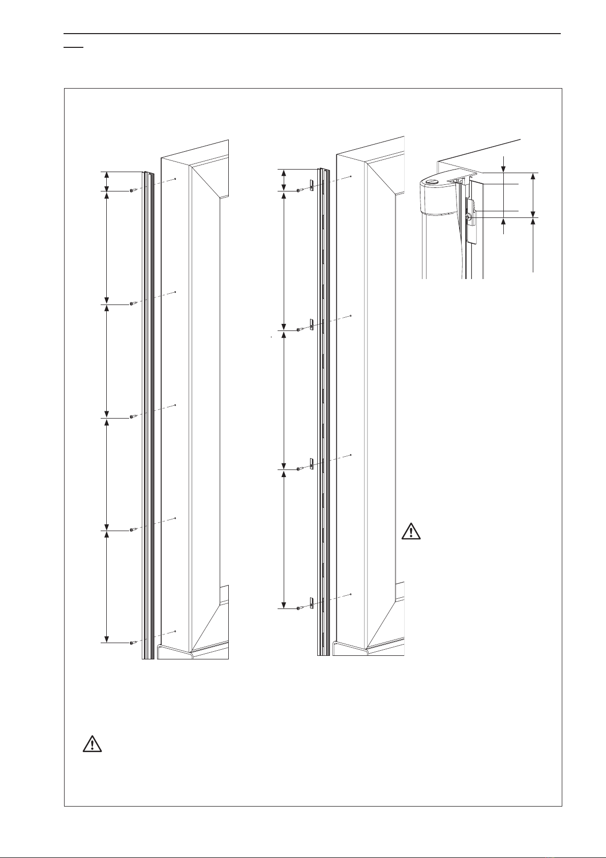
4.2 Mounting the mounting prole
The mounting prole must be mounted on a at surface.
1. Use XL-QFIX screws to secure the
XL-QME quick-fastening clips rmly in
place, as shown in the illustration.
2. Hook the prefabricated sensors into
the mounted fastening clips.
3. Using a plastic hammer and a mode-
rate degree of force, drive the
mounting prole into the teeth in the
clips as far as it will go. To prevent
damage, place a suitable piece of
wood between the mounting prole
and the hammer; do not hammer
directly onto the face of the prole.
Never drive in the sensor with the end
cap attached! If an end cap has
already been attached along with its
fastening clip, loosen and fold it back
from the mounting prole, then
perform the mounting work specied
in points 2 and 3. Re-attach the end
plug once you have nished.
Hole pattern
100 mm
Mounting with quick-fastening systemMounting with screws
Use pan head or countersunk screws
Ensure that any additional holes required for the cable routing are provided in the mounting proles and door proles.

7
✓✗
✓
1 2
3 4
1 2 3
4.3 Mounting the contact prole onto the mounting prole
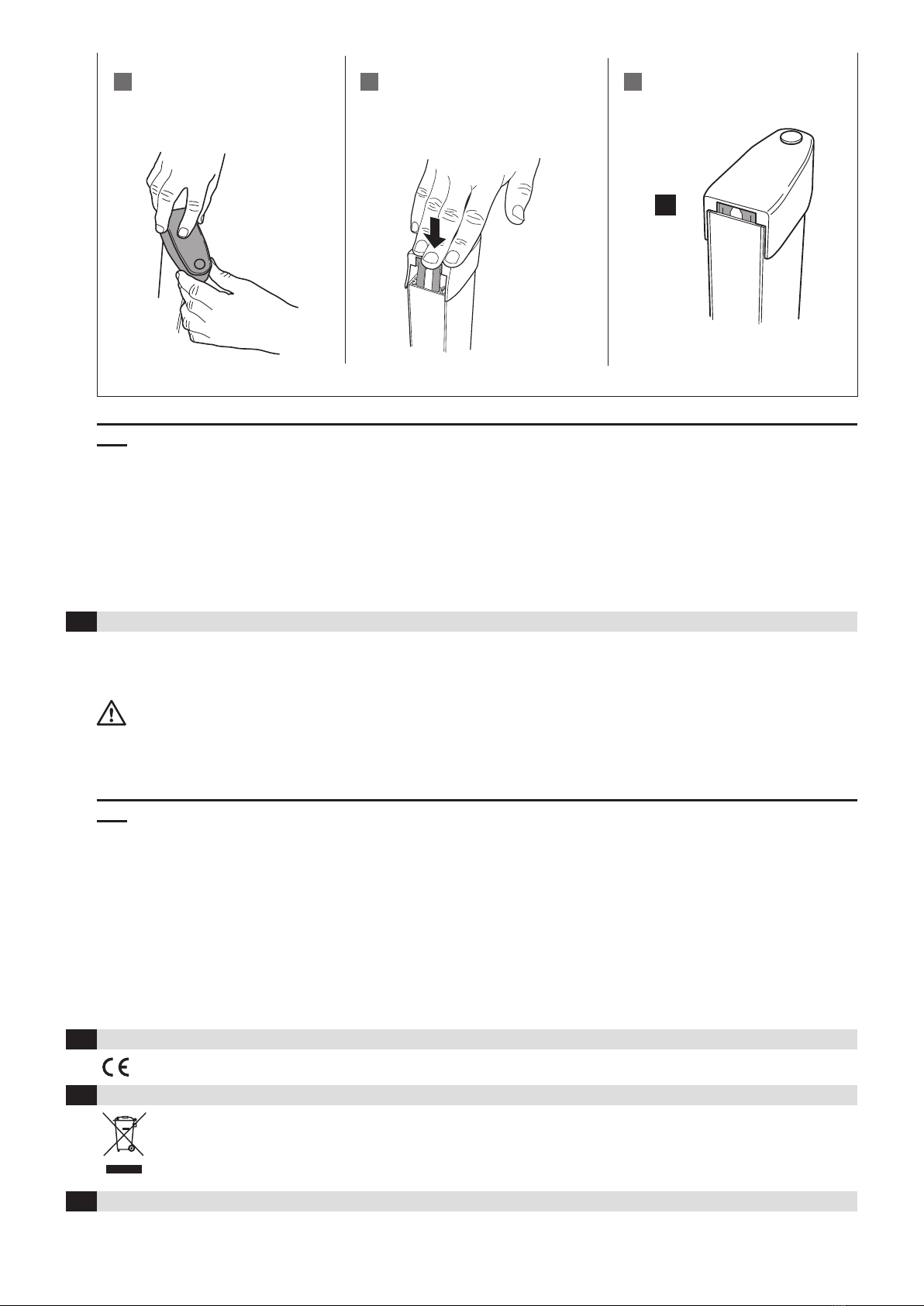
4.4 Mounting end caps
Fit the rst side of the
contact prole ush at both
ends of the mounting prole
and apply uniform pressure
to press it into the mounting
prole, working from the
ends towards the centre.
Prepare the lower end cap:
remove the drainage stud
The rubber retainers must engage fully in the mounting
prole.
Tip: Use a tool to help you to push the retainers in. Use
the curved edge to roll over the retainers, applying slight
pressure.
Push on the prole hard from the front to check
that it has been pressed in correctly. The contact
prole must not come away from the
mounting prole at any point.
Turn out the end cap at the top Pull the hole over the retainer on the
contact end piece
Tip: In case of limited accessibility, the rst side of the contact prole can be tted into the mounting prole prior to xing the mounting prole.
This can be helpful for example at folding or swing gates, when sensors are mounted near the ground.
Always work from both ends
towards the centre when
pushing in the prole.
This prevents unwanted
elongation of the rubber
proles.
8
BBC Bircher Smart Access, BBC Bircher AG, Wiesengasse 20, CH-8222 Beringen, www.bircher.com
5 6
✓
4
4.5 Checking the sensor installation
Once mounting work has been completed, the sensor must be tested to ensure it is
functioning correctly. Measure the resistances by actuating the sensor at several
points:
Sensor actuated: ≤ 500 Ω
Sensor not actuated with XL-RP8 resistor plug: resistance between 8.0 and 9.0 kΩ
5Commissioning
Once the sensor has been installed, it must be connected to the safety switching device.
The operating instructions for the corresponding safety switching device
must be followed when making the connection as well as when carrying out
subsequent installation and commissioning work.
8Contact
Position the end cap and pull it over the
prole
Position the fastening clip and push it in as
far as it will go
Correct end position
5.1 Note for prefabricated XL sensors with integrated XRF-TI radio transmitter
If the XRF-TI radio transmitter is integrated, the operating instructions for this are enclosed with the sensor. The end of the sensor to which the
integrated radio transmitter is connected has a corresponding marking underneath the mounting prole.
6EU Declaration of Conformity
See attachment
7WEEE
Devices with this symbol must be treated separately during disposal. This must be done in accordance with the laws of
the respective countries for environmentally sound disposal, processing and recycling of electrical and electronic equipment.
This manual suits for next models
15
Other BBC Bircher Accessories manuals


