Parish Cheetah DC2000 User manual

OWNER'S MANUAL
IMPORTANT: READ OWNER'S MANUAL CAREFULLY
MODEL : CHEETAH DC2000

TABLE OF CONTENTS
Safety Precautions
Machine Operation
Machine Maintenance & Storage
Parts Lists
Wiring Diagram
Warranty Policy
3
4-5
5
6-11
12
13
-2-

SAFETY PRECAUTIONS
!!! This machine must be grounded! Grounding
provides the path of least resistance for
electrical current. To reduce the risk of electrical
shock should the machine malfunction, the
machine has a special grounding plug. Do not
remove the ground pin under any circumstances!
This machine is intended for commercial use. It
is constructed for use in an indoor environment
and is not intended for any other use. Use only
recommended accessories.
All operators shall read, understand and
exercise the following safety precautions:
1]Do not operate machine:
- Unless trained and authorized.
- Unless you have read and understand
operators manual.
- In flammable or explosive areas.
- With damaged cord or plug.
- If not in proper operating condition.
- In outdoor areas.
- In standing water.
- Without bag / filters in place.
- With the use of extension cords.
2]Before operating machine:
-Make sure all safety devices are in place
and operate properly.
3]When using machine:
- Only use approved burnishing pads.
- Do not run machine over cord.
- Do not pull machine by cord or plug.
- Do not pull cord around sharp edges or
corners.
- Ensure the dust collection bag is in place
and is tightly sealed to the machine.
- Turn power switch to “off “ prior to
unplugging machine.
- Do not unplug by pulling on the cord.
- Do not stretch cord.
- Do not handle plug with wet hands.
- Keep cord away from heated surfaces.
- Do not pick up burning or smoking
debris such as cigarettes, matches or
hot ashes.
- Report machine damage or faulty
operation immediately.
4]Before leaving or servicing machine:
- Turn off machine.
- Unplug cord from outlet.
5]When servicing machine:
- Unplug cord from outlet.
- Use manufacturer supplied or approved
replacement parts.
-3-

Operation of High Speed Floor Machine
* THIS IS A SPECIALIZED MACHINE WHICH
REQUIRES THE OPERATOR TO UTILIZE A
TRIPLE S APPROVED PAD,AND MUST BE
ADJUSTED PROPERLY TO ENSURE THE
HIGHEST POSSIBLE PERFORMANCE
AND PRODUCTIVITY.
*Read operators manual thoroughly prior
to operating or servicing this machine.
GENERAL USE
1] Remove any obstructions or other
obstacles in the area which is to be
cleaned.
2] Remove dust recovery bag and empty it out
in a trash receptacle. Replace dust
recovery bag on machine, ensuring it is
sealed tightly to the machine.
3] Place handle in upright position and tilt
machine back until handle rests on the
floor.
* Be sure the machine is not plugged into
an outlet.
4] Remove the pad center gripping device by
unscrewing the thumbscrews.
5] Place a "Triple S approved" burnishing pad
on the pad driver and re-attach the
center gripping device. (check with your
local distributor for approved pads)
6] Place machine back into its upright position.
7] Plug power cord into grounded outlet.
*Do not use an extension cord in
conjunction with the standard power cord.
8] The handle height may be adjusted by
lifting up on the handle release lever,
located on the right side of the switch
housing. Pull trigger and lower handle
to desired operating position. Release
trigger to lock handle into place.
9] To start the machine, push on the red
safety release button located on the top
of the switch housing and squeeze either
switch lever.
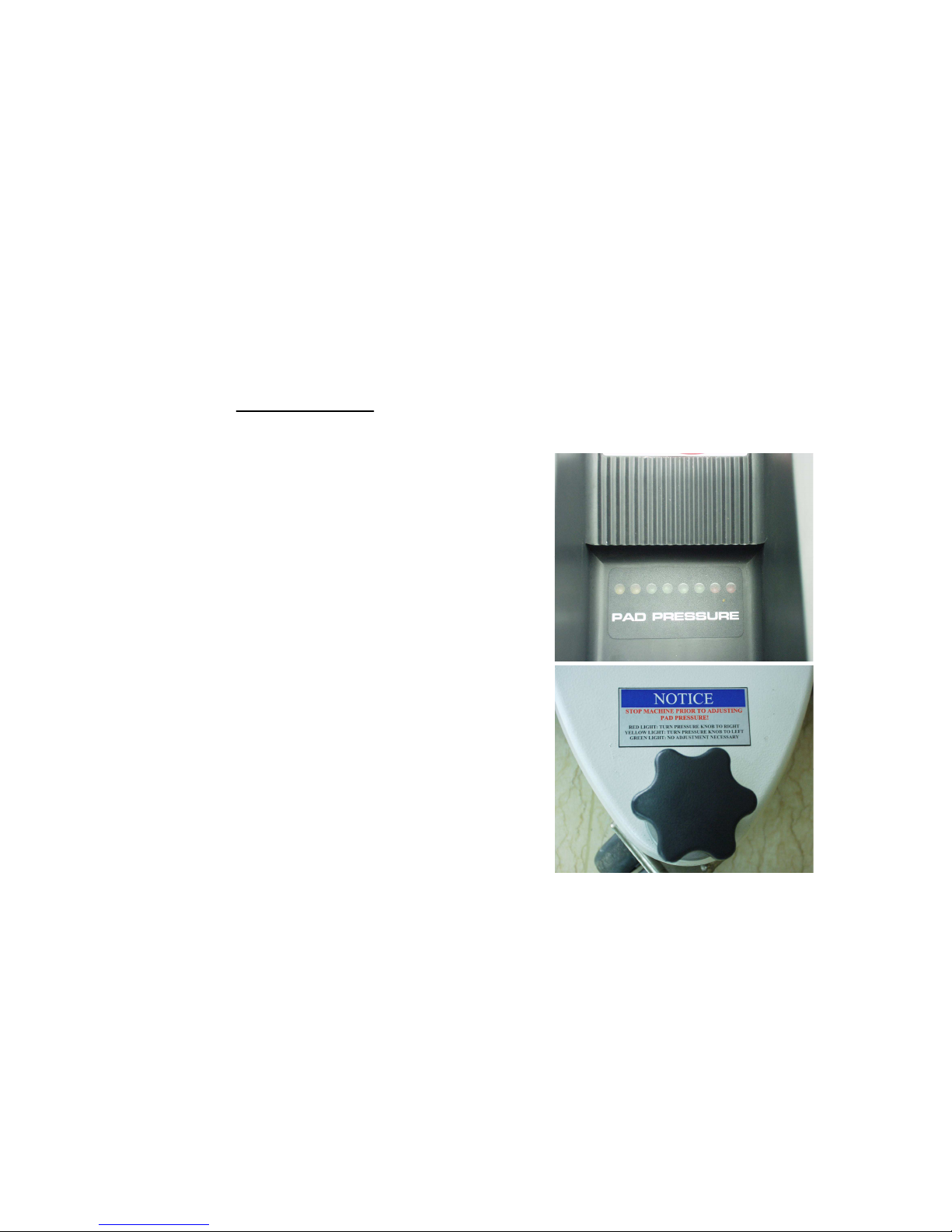
10]Once the machine has reached operating
speed, look at the digital pad pressure
meter located on the top of the motor cover.
There are 3 light colors which will help you
determine optimal pad pressure for
operating the machine. RED LIGHT(S): If
one or both red lights are illuminated, stop
the machine and turn the pad pressure
-4-

adjustment knob to the right to reduce pad
pressure. YELLOW LIGHT(S): If one or
both yellow lights is illuminated, stop the
machine and turn the pad pressure
adjustment knob to the left to increase the
amount of pad pressure. GREEN LIGHT(S):
If one, two or three green lights are
illuminated, the machine is running at the
optimal pad pressure and you may begin
working.
11] When the machine is in operation, both
hands should be gripping on the handle.
12] To stop the machine at any time,
simply release the switch lever, and the
machine will stop automatically.
MAINTENANCE
To keep the machine performing well for many
years, please follow the following maintenance
procedures.
*Always confirm that the machine is
unplugged prior to performing any
maintenance or repairs.
1] Unplug machine as soon as you are done
using it.
2]Remove dust recovery bag and empty
contents into a trash receptacle. Inspect
dust recovery bag for any damage prior to
replacing it on the machine.
3] Clean the outside of the machine with a mild
cleaner.
4] Check power cord for any damage. If any
damage is detected, replace the cord
immediately.
5] Lubricate wheels with a water resistant
lubricant every month.
6] Check machine for loose or missing nuts
and bolts, and replace as necessary.
7] If the machine is used in a dusty
environment, you may remove the motor
cover and blow the motor clean with
compressed air. This will allow for good
ventilation and help the motor run cooler.
STORAGE
1] Unplug machine from power source.
2] Store in upright position in a dry area.
-5-

-6-
PARTS LIST
BASE GROUP

DIA
NO PART
NUMBER DESCRIPTION NO
REQ'D
1 VF52114 PLASTIC STAND, RIGHT 1
2 VF52115 PLASTIC STAND, LEFT 1
3 VF54048 CONNECTOR, MOTOR COVER 1
4 VV20509 SCREW, M5x10, PH 17
5 VF54017TR LABEL 2
6 VF54047TR COVER, MOTOR 1
7 VF13503 NUT, NYLON INSERT, M8 3
8 VF13524 WASHER, PLAIN 3
9 VF54020 RIGHT ARM 1
10 VF54019 LEFT ARM 1
11 GT13016 SCREW, M8x60, HEX SOCKET 3
12 VA13480 SCREW, M8x40, HEX SOCKET 4
13 VF13519 WASHER, LOCK,φ8 5
14 VF54009 BUSHING 2
15 VF14007 HEX SCREW, M10x32 2
16 VF54010 ADJUSTMENT SCREW 1
PARTS LIST
17 VF14078 SCREW, M3x10, PH 4
18 ZW42540A LED DISPLAY PANEL 1
19 VF54046 RISING SCREW 4
20 VF54004 WHEEL BRACKET 1
21 VF50119 WAVE WASHER, φ12 4
22 VF52017N WHEEL, 5" 4
23 VF13666 WASHER, PLAIN, φ12 4
24 VF44012 SCREW, M5x12.7 4
25 VF54005 RETAINER PLATE, AXLE 2
26 VV13621 SCREW, ST5x20 6
27 VA13474 SCREW, M5x16, PH 2
28 VF13474A WASHER, PLAIN, φ5xφ16 4
29 VF54015TR BUMPER 1
30 VA14010 SCREW, M5x20, PH 2
31 VF54016 CLAMP, SKIRT 1
32 VF13517 WASHER, PLAIN, φ10 6
33 VF13518 WASHER, LOCK, φ10 6
34 GT13097 HEX SCREW, 3/8"-16x1.25" 4
35 VF52008 SPACER 1
36 VF99024 PAD HOLDER, 20" 1
37 VF52021 WASHER, PLAIN 1
38
GT13018
HEX SCREW, M8x30
1
38
GT13018
HEX SCREW, M8x30
1
-7-

DIA
NO PART
NUMBER DESCRIPTION NO
REQ'D
39 VF54027 LOCK WASHER, BIG MOUTH 1
40 VF99003A BIG MOUTH 1
41 VF54006 FLEXIBLE SKIRT 1
42 VF54011 CASTER, DUAL SWIVEL 1
43 VF54028 SCREW BUSHING, HOUSING 1
44 VF54001TR HOUSING 1
45 VF54025 ADJUSTMENT DECAL 1
46 VF54036 HOOK, COVER, DUST BAG 1
47 VF50108 NUT 1
48 VF14081 NUT, M12 1
49 VF50103A ADJUSTING KNOB, CASTER 1
50 VF54021 SPACER 2
51 ZD40205 KEY, MOTOR SHAFT 1
52 VF54007 ELBOW ADAPTOR 1
53 VF13022 SCREW, M4x12, PH 2
54 VF54003 DUST COLLECTOR BAG 1
PARTS LIST
55 ZD40B MOTOR, 120V 1
56 VF52022 THERMAL CONDUCTION GASKET 1
57 VF44204 RECTIFIER 1
58 VF52023 COVER, RECTIFIER 1
59 VF54040 RISER, ARM 2
60 GT13032 WASHER, PLAIN, φ6xφ16 1
61 VF14232 HEX SCREW, M6x10 1
62 VF54008 PIVOT BLOCK, ADJUSTOR 1
63 VF54014TR COVER, DUST BAG 1
64 VF13544 SCREW, ST4x10 4
65 VF47035TR "SSS" LOGO 1
-8-

-9-
PARTS LIST
HANDLE GROUP

DIA
NO PART
NUMBER DESCRIPTION NO
REQ'D
1 VF47009 FRONT COVER, GEAR SEAT 1
2 VF54037 GEAR SEAT 1
3 VF47028 GEAR & LEVELING INSERT KIT 1
4 GV40227 WASHER, NYLON 2
5 GV40228 "O" RING, GEAR SEAT 2
6 VF50120A GROMMET 2
7 VF47015 REAR COVER, GEAR SEAT 1
8 VF14080 SELF-TAPPING SCREW, ST4x25 2
9 VF14000 SELF-TAPPING SCREW, ST4x35 2
10 VF47046 SEAL RING 1
11 VF47045A HOOK, CABLE 1
12 VF13616 SCREW, HEX SOCKET, M10x55 1
13 GT13019 HEX SCREW, M6x40 4
14 VF47052 GEAR & LEVELING INSERT KIT 1
15 GT13013 NUT, M4 4
16 VF47103 LEVELING ROD 1
PARTS LIST
17 VF47007 SPRING, LEVELING 1
18 VF47033 RETAINER 1
19 VF47008 SEAL, TUBE 1
20 VF47102 TUBE 1
21 VA13474 SCREW, M5x16, PH 1
22 VA13476 SCREW, M5x40, PH 1
23 VF45119U CORD, POWER SUPPLY, STOW 14/3C 1
24 VF54043TR SERIAL TAG 1
25 VF14212 SCREW, M3x25, PH 2
26 VF13511 WASHER, LOCK, INTERNAL TOOTH 2
27 VF44203 SWITCH ASSY, 20A, 250V 1
28 VF45124A JUMP WIRE 1
29 VV13650 SCREW, M4x10, PH 2
30 VF48309 BLOCK, HANDLE CABLE 1
31 VF46703TR OPERATING TRIGGER, LEFT 1
32 AS22009 STRAIN RELIEF, CORD 1
33 VF52107 COVER, SOLUTION LEVER 1
34 VF14226 SCREW, FH, M6X35 2
35 VF52118TR REAR COVER, SWITCH HOUSING 1
36 VF54029 DECAL, NOTICE 1
37 VF14218 SCREW, M6x40, PH 2
38
VF46705
SAFETY BLOCK
1
38
VF46705
SAFETY BLOCK
1
-10-

DIA
NO PART
NUMBER DESCRIPTION NO
REQ'D
39 GV40218 SPRING, SAFETY BLOCK 1
40 VF99010C CIRCUIT BREAKER, 17A 1
41 VF13527 EXTERNAL TOOTH, WASHER, φ4 1
42 VF13526 SCREW, HOLDING, M4x30 1
43 VF46704TR OPERATING TRIGGER, RIGHT 1
44 VF48306 PIN, LEVER 3
45 GT13014 NUT, M4, NYLON INSERT 1
46 VF46707TR TRIGGER, HANDLE ADJUSTMENT 1
47 GT13017 BIG WASHER, PLAIN, φ4xφ16 1
48 VF46706TR HANDLE GRIP 2
49 VF46701TR FRONT COVER, SWITCH HOUSING 1
50 VF47035TR "SSS" LOGO 1
51 VF13600 WASHER, PLAIN, φ6 4
52 VF13502 NUT, NYLON INSERT, M6 4
53 VF45120 CABLE, HANDLE, SJTW 14/3C 1
PARTS LIST
-11-

STOW14/3C
Power
Supply
Cord
Cord
Handle
SwitchHousing
Green
White
Black
Switch
BLACK
RED
Green PCB
Black Red
Black
~
~
+
Rectifier
White
White
LED
-12-
Wiring Diagram

WARRANTY POLICY
The warranty terms outlined below are in lieu of any other warranties, either stated or implied,
including any implied warranty of merchantability, fitness for a particular purpose or otherwise.
Under no circumstances will seller be liable for any loss, damage, expense or consequential
damages arising in connection with the use or inability to use this product.
This warranty does not apply to damage or defect caused by accident, misuse, negligence, abuse,
fire or to any Triple S product which has been serviced by anyone other than a Triple S authorized
service representative. Housings or parts that have become damaged as a result of improper use
of the machine are excluded from this warranty. Refer to owner’s manual for proper machine use
and maintenance. Parts that are expected to wear from normal use and, therefore are not
covered under the parts warranty include, but are not limited to: batteries (pro-rated for one year);
bearings; belts; brushes; filters; squeegees; switches; and tires.
This warranty commences on the date of purchase of the product by the original end user from an
authorized Triple S distributor, subject to proof of purchase. If proof of purchase date is
unavailable, the warranty begins 90 days after the sale of the product to an authorized Triple S
distributor.
Subject to the conditions outlined above, the manufacturer warrants the
rotationally-molded polyethylene housings and parts on its machines to be free from
defects in materials and workmanship, under normal use and service for twelve (12)
years to the original purchaser.
Under this warranty, the manufacturer guarantees the performance of non-polyethylene
parts and components on Triple S machines to be free from defects for up to five (5)
years to the original end user. Parts replaced under this warranty are guaranteed for the
remainder of the original warranty period.
Labor charges are covered for five (5) full years from the date of purchase for Triple S
products, provided an authorized Triple S service provider is used for repair. No travel
coverage is extended for cord electric machines.
Product Exceptions & Exclusions: Battery chargers and all accessories are warranted for one
year.
Triple S reserves the right to change the warranty policy without notice.
Table of contents
Other Parish Floor Machine manuals
Popular Floor Machine manuals by other brands

WOLFF
WOLFF VARIO-STRIPPER 230 V Translation of the original operating instructions

Kranzle
Kranzle 1 + 1 Original user manual

Bartell
Bartell INNOVATECH P550Y Owner's and parts manual

Tornado
Tornado 64220 Operation & maintenance manual

Mercury
Mercury HD-22 Safe Operations

Clarke
Clarke Fusion 20 troubleshooting guide