Park House Healthcare PHP1000 User manual

Web: www.parkhouse-hc.com
The Company
Park House Healthcare is proud to offer a 24 hour telephone help care line
365 days a year with a dedicated one-on-one personal customer service at
all times. With distributors in over 35 countries, Park House healthcare are
a truly international company and place important emphasis on providing
high levels of customer care to ensure we exceed customer expectations at
all times. Additional support nationwide is available through our 6 service
centres situated strategically around the country.
Park House Healthcare is a respected member of the British Healthcare
Trade Association, and has BS EN ISO9001and EN46002 accreditation
which is the specific quality standard for Medical devices. All products are
CE marked in accordance with European Directive 93/42/EEC.
Park House Healthcare Ltd
Whitehall 26 Business Park
1 Heathfield Lane, Birkenshaw
West Yorkshire, BD11 2HW, UK
Tel: 0845 0600 333
Fax:0845 0600 334
Email: [email protected]
ISO Certificate No: 8019
CE Certificate No: CA001810
Master Indemnity Assurance No: IFA2433 0451 CCI
Due to its policy of continued developed and improvement,
Park House Healthcare Ltd reserves the right to amend any
details and specification without notice.
PHP1000 Pump
FOR USE WITH THE ELITE REPLACEMENT
AND ECLIPSE II OVERLAY SYSTEMS
Service Manual

Contents:
Page
1PRODUCT VIEW ILLUSTRATION:...................................................................................... 4
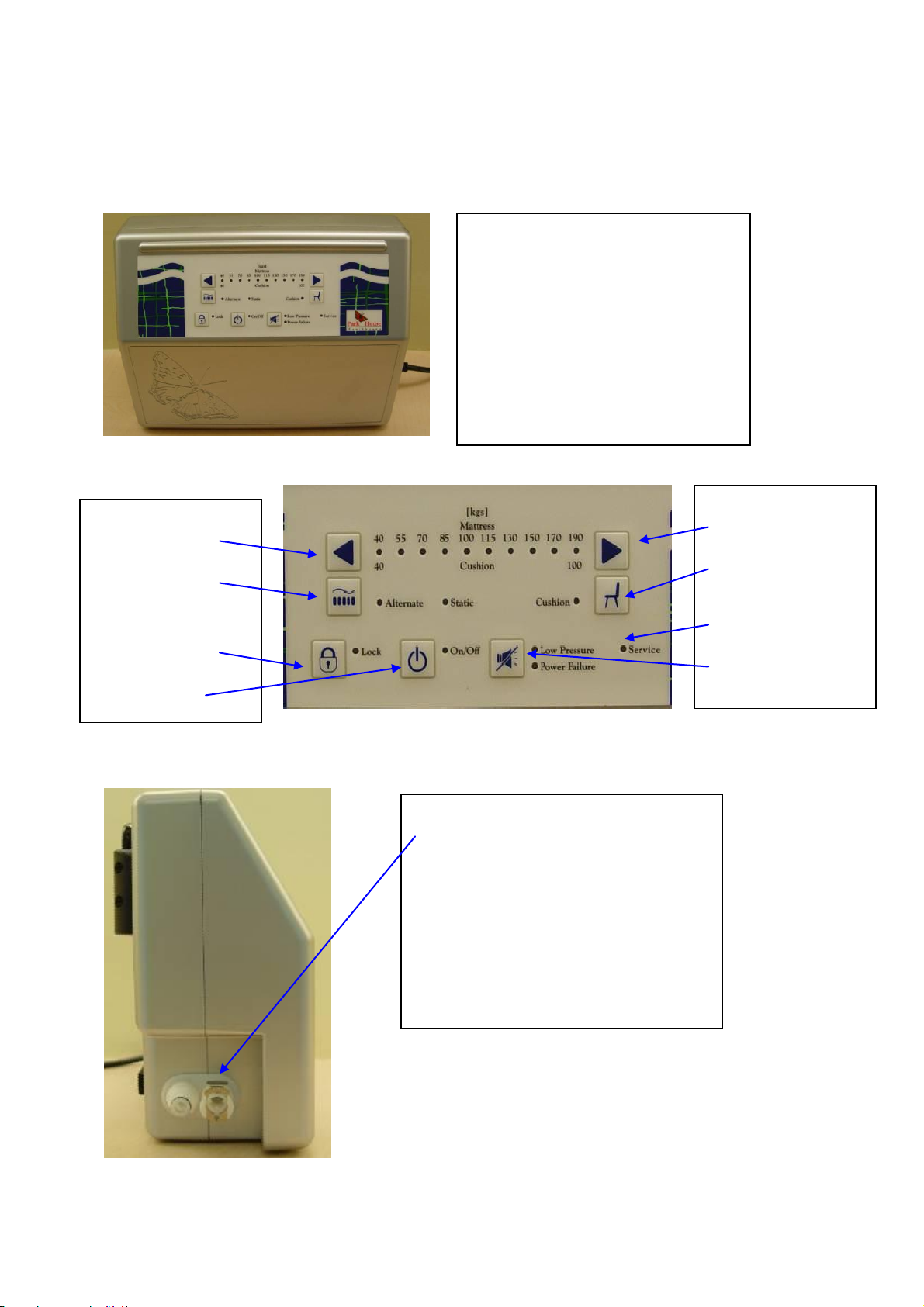
1.1 FRONT VIEW ..................................................................................................................4
1.2 PANEL VIEW ...................................................................................................................4
1.3 SIDE VIEW 1 ..................................................................................................................4
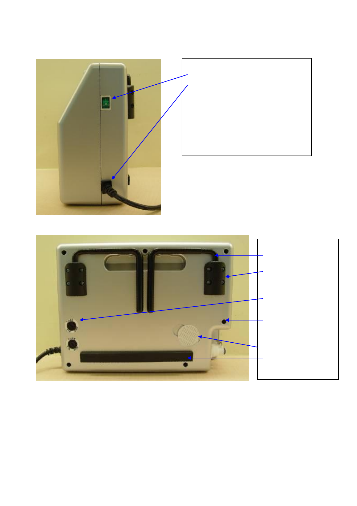
1.4 SIDE VIEW 2 ..................................................................................................................5
1.5 REAR VIEW ....................................................................................................................5
2SERVICE INSTRUCTION: .................................................................................................. 6
2.1 ALL PART ILLUSTRATION .................................................................................................... 7
2.1.1 PHP1000 Pump ..................................................................................................... 7
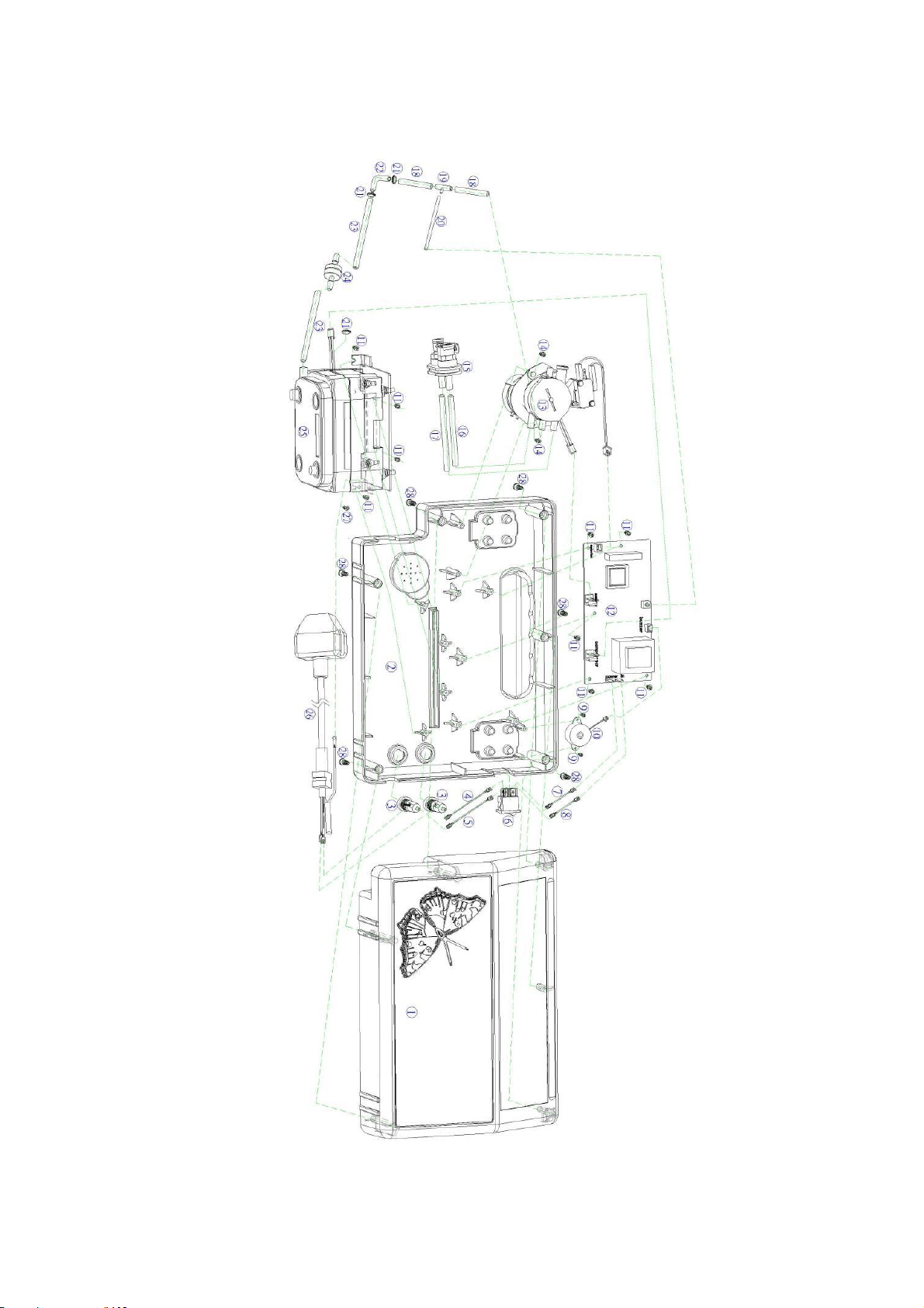
2.1.2 PUMP Exploded View Diagram………………………………………………………………………………………………9
2.1.3 PUMP ASSEMBLY BOM……………………………………………………………………………………………………………10
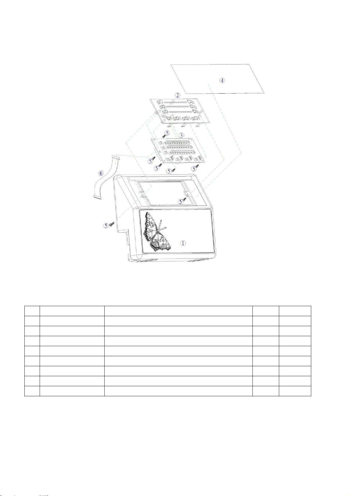
2.1.4 TOP CASE EXPLODED VIEW DIAGRAM…………………………………………………………………………………11
2.1.5 TOP CASE ASSEMBLY BOM……………………………………………………………………………………………………11
2.1.6 BASE CASE EXPLODED VIEW DIAGRAM………………………………………………………………………………12
2.1.7 BASE CASE ASSEMBLY BOM…………………………………………………………………………………………………12
3 SERVICE CHECKLIST:…………………………………………………………………………………………13
3.1 SERVICE REPAIR SOP …………………………………………………………………………………………………………………14
3.1.1 T1 CHECK PRESSURE RANGE.................................................................................. 14
3.1.2 T2 PRESSURE CALIBRATION…………………………………………………………………………………………………16
3.1.3 T3 NO POWER………………………………………………………………………………………………………………………..21
3.1.4 T4 LEAD WIRES DISCONNECTED…………………………………………………………………………………………22
3.1.5 T5 PUMP IS NOT FUNCTIONING……………………………………………………………………………………………23
3.1.6 T6 PANEL PCB LED LIGHT MALFUNCTION……………………………………………………………………………24
3.1.7 T7 BUZZER MALFUNCTION……………………………………………………………………………………………………25
4RECOMMENDED TOOLS: ................................................................................................. 26
5 Replacing the Cell System: .....................................................................27

Service Manual - PHP 1000 Pump
2008.04 V1.0
4
Side View 1
Air outlet (CPC Connector)
Panel View
Comfort
Seat cushion
Service LED
Alarm mute
Panel View
Comfort
Therapy
Panel lock
Power
1Product View illustration:
1.1 Front View
1.2 Panel View
1.3 Side view 1
Front View

Service Manual - PHP 1000 Pump
2008.04 V1.0
5
Rear View
Bed Hooks * 2
Bed Hooks
cover * 2
Fuse Box * 2
Casing
screws*6
Filter cover *1
Foam
bumper*1
Side View 2
Power switch
Power cord
1.4 Side view 2
1.5 Rear view

Service Manual - PHP 1000 Pump
2008.04 V1.0
6
2Service Instruction:
Instruction for all general service repairs
WARNING
Disconnect power cord from the
mains plug, prior to any repair
Attention:
Before commencing the repair please follow instructions indicated
from below.
Such as CPR isn’t snapped securely, See Fig A
Quick connectors are not connected securely to the control
unit, See Fig B
For all the required replacement parts, please contact
your agent for part number. Once the BOM
(Bill of Material) is obtained, proceed to the parts order
and repair as follows.
Fig A
Fig B

Service Manual - PHP 1000 Pump
2008.04 V1.0
7
2.1 All part illustration
2.1.1 PHP 1000 Pump
1.Buzzer
2.Control PCB
3.Power switch
4.Timing motor and
control assembly
5.Fuse*2
6.Compressor
assembly
7.Power cord socket
8.Connector
assembly
1.Pressure
sensor
3.PCB Wiring
connection
site_#1
5.Timing
motor micro
switch socket
4. Timing
motor and
control
assembly
socket
2.compressor
assembly
socket
6.Buzzer socket
7.Main PCB
power socket
Fig_1-1
Fig_1-2

Service Manual - PHP 1000 Pump
2008.04 V1.0
8
1.Micro switch
securing
screws_x2
2.Timing
Motor
screws_x2
3. Buzzer
securing
screws_x2
4.Main PCB
securing
screws_x5
5.Grounding nut
1. Front panel
PCB securing
screws_x5
2. PCB Wiring
connection
site_#1
Fig_1-3
Fig_1-4

Service Manual - PHP 1000 Pump
2008.04 V1.0
9
2.1.2 PUMP Exploded View Diagram
Fig 2-1

Service Manual - PHP 1000 Pump
2008.04 V1.0
10
2.1.3 PUMP Assembly BOM
NO
Item
Description
UOM
Quantity
1
F640A01-0000
Top case assembly
PCS
1
2
F642A01-C080
Base case assembly
PCS
1
3
F192A01-0000
Fuse holder assembly
PCS
2
4
884203-0000
Lead wire, brown
PCS
1
5
884204-0000
Lead wire, blue
PCS
2
6
464302-0000
Power switch
PCS
1
7
664208-0000
Lead wire, brown
PCS
1
8
664209-0000
Lead wire, blue
PCS
1
9
505001-0000
Screws
PCS
2
10
504001-0000
Buzzer
PCS
1
11
885013-0000
Screws
PCS
9
12
F647A01-0000
Control PCB
PCS
1
13
F644E01-0000
Timing motor assembly
PCS
1
14
885012-0000
Screws
PCS
2
15
F016A01-0000
Air outlet assembly
PCS
1
16
F425A04-0000
Silicone tubing
PCS
1
17
F195A06-0000
Silicone tubing
PCS
1
18
F195A01-0000
Silicone tubing
PCS
2
19
951708-0000
3 ways connector tubing
PCS
1
20
F235A01-0000
Silicone tubing
PCS
1
21
991811-0000
Cable Ties
PCS
3
22
371707-0000
L tubing
PCS
1
23
F425A03-0000
Silicone tubing
PCS
2
24
Y012A02-0000
Check valve
PCS
1
25
F643E01-0000
Compressor assembly 230V/50Hz, 8 Liter
PCS
1
26
F647A02-0000
Power cord assembly
PCS
1
27
885014-0000
Screws
PCS
1
28
885010-0000
Screws
PCS
6

Service Manual - PHP 1000 Pump
2008.04 V1.0
11
Fig_2.2
2.1.4 Top Case Exploded View Diagram
2.1.5 Top case assembly BOM
NO
Item
Description
UOM
Quantity
1
F641201-C080
Base case
PCS
1
2
F372A01-0000
Hanger assembly
PCS
2
3
371708-0000
Hanger cover
PCS
2
4
955002-0000
Screws
PCS
8
5
611702-0000
Filter cover
PCS
1
6
881708-0000
Air filter sponge
PCS
1
7
373403-0000
Foam bumper
PCS
1
8
882401-0000
Fuse specification sticker
PCS
2

Service Manual - PHP 1000 Pump
2008.04 V1.0
12
Fig_2.3
2.1.6 Base case Exploded view diagram
2.1.7 Base case assembly BOM
NO
Item
Description
UOM
Quantity
1
F641201-C080
Base case
PCS
1
2
F372A01-0000
Hanger assembly
PCS
2
3
371708-0000
Hanger cover
PCS
2
4
955002-0000
Screws
PCS
8
5
611702-0000
Filter cover
PCS
1
6
881708-0000
Air filter sponge
PCS
1
7
373403-0000
Foam bumper
PCS
1
8
882401-0000
Fuse specification sticker
PCS
2

Service Manual - PHP 1000 Pump
2008.04 V1.0
13
3Service checklist
General symptom encountered
SOP
Check pressure range
T1
Pressure calibration
T2
No Power
T3
Lead wires disconnected
T4
Pump is not functioning
T5
Panel PCB LED light malfunction
T6
Buzzer malfunction
T7

Service Manual - PHP 1000 Pump
2008.04 V1.0
14
3.1 Service repair SOP
3.1.1 T1 Check pressure range
T1
Confirm pressure range (For PHP 1000 pressure testing)
SOP:
1. First plug the power cord in; to switch on the power, push the power button on
the panel, then make the pump operate.
2. Use a pressure meter, with mmHg measurement only, and connect to the air
outlet securely (make sure connecting to the connector which air is moving
out). If the connector from pressure meter to the control unit cannot fit
securely, please find appropriate connectors or ask your contact agent for
assistance. Once the connection is air tight, observe the pressure to reach
required pressure level. (For the pressure meter, please refer to “Required
tooling checklist”)
3. Set the pressure to the lowest level 1 and use a pressure meter to check that
the lowest pressure is within the set pressure range.
4. Set the pressure to the highest level 10 and use a pressure meter to check
that the highest pressure is within the set pressure range.
5. If the pressure range is not correct, perform the following check found from
next page.

Service Manual - PHP 1000 Pump
2008.04 V1.0
15
T1
Confirming pressure range (For PHP 1000 abnormal
pressure checklists)
SOP:
6. Follow the instructions below to assemble the testing equipment, verify
that all the connections are air-sealed.
7. Turn on the pump and wait for the mattress to be completely filled by the
pump, and observe that the pressure is correct.
8. While adjusting the pressure, the alarm should not be activated whether in
high or low pressure at any time during testing.
9. Follow the checklist below if an incorrect pressure is detected.
10. Air leak detected from timing motor? See timing motor and control
assembly(APPENDIX)。
11. Leaks found from air tubing? (Pump exploded view diagram)
12. Incorrect compressor performance. See compressor assembly?
(APPENDIX)
13. Air tubing connecting to the sensor has been disconnected or loosened
fittings? (Pump exploded view diagram)
14. Errors persists even after above mentioned problem checklists, proceed to
the PCB replacement section found in the Controller wiring diagram.

Service Manual - PHP 1000 Pump
2008.04 V1.0
16
3.1.2 T2 Pressure calibration
T2
Pressure calibration (For PHP 1000 pressure calibration
procedure)
SOP:
If the problem encountered isn’t included from, 10th, 11th, 12th, 13th and 14th step of
T1, follow the steps below to calibrate the pressure.
STEP-1:Switch on the power. The normal power supply light
will be illuminated.
STEP-2:Press the comfort left/right selection
button, and the power button together for 5
seconds, then enter in the calibration procedure
(the appropriate buttons can be found by referring
to the left figure).
Comfort left/right selection button
Power button
Power switch

Service Manual - PHP 1000 Pump
2008.04 V1.0
17
T2
Pressure calibration (For PHP 1000 pressure calibration
procedure)
SOP:
STEP-4:Enter in the calibration procedure, the
On/Off LED will be lit up, while the
remaining LED lights should not be lit. The
compressor will not function because the
timing motor is in the repositioning process.
STEP-5:Wait for the timing motor repositioning
process to finish, the low pressure LED light
will be lit up and flash. The compressor will
start to work and can begin to calibrate.
STEP-6:Make sure the pump isn’t obstructed in the air
inlet, and the air output is normal.
On/Off LED lit up
Low Pressure Light

Service Manual - PHP 1000 Pump
2008.04 V1.0
18
T2
Pressure calibration (For PHP 1000 pressure calibration
procedure)
SOP:
STEP-7:Press the alarm mute button, the low
pressure LED will turn off. The LED lights of
Comfort 1 and Comfort 2 will light up and
flash, and the compressor will stop
working. It means the pulling air tubing
calibration was finished, and then it could
begin to perform a low pressure
calibration.
STEP-8:Provide a stable 30 mmHg pressure.
Comfort 1 & Comfort 2 LED
30mmHg

Service Manual - PHP 1000 Pump
2008.04 V1.0
19
T2
Pressure calibration (For PHP 1000 pressure calibration
procedure)
SOP:
STEP-9:Press the Alarm mute button, the LED
lights of Comfort 1 and Comfort 2 will
turn off. After that, the LED lights of
Comfort 9 and Comfort 10 will light up
and flash, and the compressor will stop
working. It means the low pressure
calibration is finished, and then proceed
to perform a high pressure calibration.
STEP-10:Provide a stable 60 mmHg pressure.
Comfort 9 & Comfort 10 LED
60mmHg

Service Manual - PHP 1000 Pump
2008.04 V1.0
20
T2
Pressure calibration (For PHP 1000 pressure calibration
procedure)
SOP:
STEP-11:Press the Alarm mute button, the LED
lights of Comfort 9 and Comfort 10
will turn off. The LED light of On/Off
will flash 5 times and then turn off.
The pressure calibration procedure is
now finished.

Service Manual - PHP 1000 Pump
2008.04 V1.0
21
3.1.3 T3 No power
T3
Replacing blown fuse
SOP:
1. Use a screwdriver and turn counter-clockwise to remove fuse from the box.
See Fig_1
Fig_1 Fug_2
2. Observe inside of the fuse whether disconnected by the power surge or
incorrect voltage input.
3. Replace the new fuse and insert back to the box. Fasten by using in-line
screwdriver turning clockwise to fasten the fuse box. See Fig_2
4. Every time the fuse is blown, please also check parts inside the pump for any
damages (check for any disconnected wires or blackened area from PCB). Once
the inspection is complete, plug the cord back to the mains to inspect
functions.
Table of contents
Popular Water Pump manuals by other brands

Pentair Pool Products
Pentair Pool Products PENTEK G2DT-01 Owner and operational manual

Annovi Reverberi
Annovi Reverberi AR 1064 instruction manual

Grundfos
Grundfos UP instructions

nomad
nomad PWR FLO NPF07 Series Operation manual

Server
Server BP-1 quick start guide

Ardisam
Ardisam EarthQuake WP4310 Operating & parts manual

Eaton
Eaton Vickers PVE12 Overhaul manual

BALZER
BALZER Lagoon user manual

BUSCH
BUSCH COBRA BC 0200 F Installation and maintenance instructions

Oase
Oase Aquamax Gravity Eco 10000 operating instructions

Charles Bentley & Son
Charles Bentley & Son GARDEN GLPUMP400 Assembly instructions

EQUIPCO
EQUIPCO BT46SK instructions