manuals.online logo
Brands
  1. Home
  2. •
  3. Brands
  4. •
  5. Parrot Uncle
  6. •
  7. Fan
  8. •
  9. Parrot Uncle F6223 Manual

Parrot Uncle F6223 Manual

Installation & Operating Instructions for the
F6223
Parrotuncle Owner’s Installation ,Manual
WARNING: SHUT POWER OFF AT FUSE OR CIRCUIT BREAKER
Parrotuncle Lighting, 218 Black Tie Lane, Chapel Hill, NC www.parrotuncle.com
Parrot Uncle YOU CAN BE SURE OF are trademarks of Eileen Grays LLC. Used under license by Eileen Grays LLC. Made in China
SKU egatloVdetaR Light CCT.. )rotom(rewopdetaR
49W
THANK YOU FOR YOUR PURCHASE
instructions before using the product
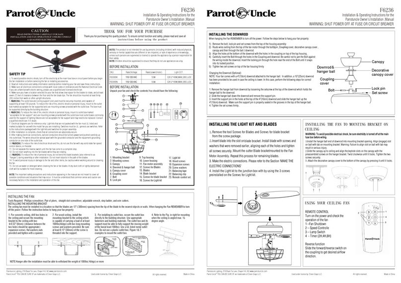
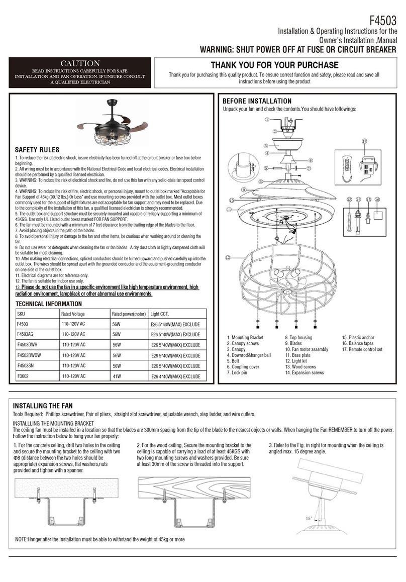
1. Mounting bracket
2. Mounting screws
3. Canopy
4. Downrod & hanger ball
5. Canopy cover
6. Lock pin
8. Coupling cover
9. Fan motor assembly
10. Center flywheel
11. Blades
12. Light pan
13. Screws for light shade
15. Wood screws
16. Expansion screws
17. Screw washers
18. Balancing tape
19. Balancing clip
20. Remote control set.
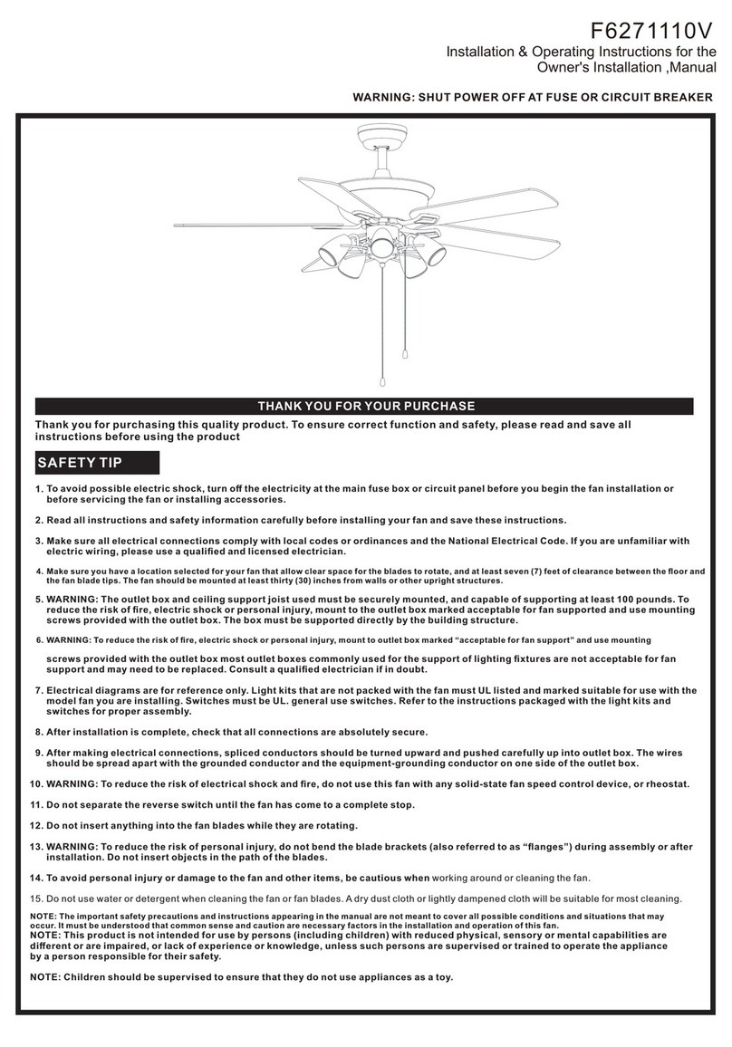
BEFORE INSTALLATION
Unpack your fan and check the contents.You should have the following:
CAUTION
READ INSTRUCTIONS CAREFULLY FOR SAFE
1.To avoid possible electric shock, turn off the electricity at the main fuse box or circuit panel before you begin
the fan installation or before servicing the fan or installing accessories.
2. Read all instructions and safety information carefully before installing your fan and save these instructions.
3. Make sure all electrical connections comply with local codes or ordinances and the National Electrical Code.
If you are unfamiliar with electric wiring, please use a qualified and licensed electrician.
4. Make sure you have a location selected for your fan that allow clear space for the blades to rotate, and at least
seven (7) feet of clearance between the floor and the fan blade tips. The fan should be mounted at least thirty
(30) inches from walls or other upright structures.
5.WARNING:The outlet box and ceiling support joist used must be securely mounted, and capable of
supporting at least 100 pounds. To reduce the risk of fire, electric shock or personal injury, mount to the outlet
box marked acceptable for fan supported and use mounting screws provided with the outlet box. The box must
be supported directly by the building structure.
6.WARNING:To reduce the risk of fire, electric shock or personal injury, mount to outlet box marked
“acceptable for fan support” and use mounting screws provided with the outlet box most outlet boxes commonly
used for the support of lighting fixtures are not acceptable for fan support and may need to be replaced. Consult
a qualified electrician if in doubt.
7. Electrical diagrams are for reference only. Light kits that are not packed with the fan must UL listed and
marked suitable for use with the model fan you are installing. Switches must be UL. general use switches. Refer
to the instructions packaged with the light kits and switches for proper assembly.
8. After installation is complete, check that all connections are absolutely secure.
9. After making electrical connections, spliced conductors should be turned upward and pushed carefully up
into outlet box. The wires should be spread apart with the grounded conductor and the equipment-grounding
conductor on one side of the outlet box.
10.WARNING:
To reduce the risk of electrical shock and fire, do not use this fan with any solid-state fan speed
control device, or rheostat.
11. Do not separate the reverse switch until the fan has come to a complete stop.
12. Do not insert anything into the fan blades while they are rotating.
13.WARNING:To reduce the risk of personal injury, do not bend the blade brackets (also referred to as
“flanges”) during assembly or after installation. Do not insert objects in the path of the blades.
14. To avoid personal injury or damage to the fan and other items, be cautious when working around or cleaning
the fan.
15. Do not use water or detergent when cleaning the fan or fan blades. A dry dust cloth or lightly dampened
cloth will be suitable for most cleaning.
NOTE:The important safety precautions and instructions appearing in the manual are not meant to cover all
possible conditions and situations that may occur. It must be understood that common sense and caution are
necessary factors in the installation and operation of this fan.
All rights reserved.
NOTE:This product is not intended for use by persons (including children) with reduced physical,
sensory or mental capabilities are different or are impaired, or lack of experience or knowledge,
unless such persons are supervised or trained to operate the appliance by a person responsible for
their safety.
NOTE:Children should be supervised to ensure that they do not use appliances as a toy.
BEFORE INSTALLATION
INSTALLING THE FAN
Tools Required: Phillips screwdriver, Pair of pliers, straight slot screwdriver, adjustable wrench, step ladder, and wire cutters.
INSTALLLING THE MOUNTING BRACKET
The ceiling fan must be installed in a location so that the blades are 12”( 300mm) spacing from the tip of the blade to the nearest objects or walls. When hanging the Fan REMEMBER to turn
off the power. Follow the instruction below to hang your fan properly:
NOTE:Hanger after the installation must be able to withstand the weight of 100lbs( 45kgs) or more
1. For concrete ceiling, drill two holes in
the ceiling and secure the mounting
bracket to the ceiling with two
Φ0.32”(8mm)(distance between the
two holes should be appropriate)
expansion screws, flat washers,nuts
provided and tighten with a spanner.
2. For wood ceiling, install the
mounting bracket to the ceiling which
is capable of carrying a load of at least
100lbs(45kgs) with two long mounting
screws and washers provided. Be sure
at least 0.12”(30mm) of the screw is
threaded into the support.
3. For installing to outlet box, secure the outlet box
directly to the building structure. Use appropriate
fasterners and building materials. The outlet box and its
support must be able to fully support the moving weight
of the fan(at least 100lbs). Use a UL listed metal outlet
box. Do not use a plastic outlet box. Figure 1& 2
examples to mount the outlet box.
4. Refer to the Fig. in right for mounting
when the ceiling is angled max. 15
degree angle.
E12 3*40W(MAX.)EXCLUDE3
INSTALLATION AND FAN OPERATION.IF UNSURE CONSULT
A QUALIFIED ELECTRICIAN
1
7
2
3
4
5
6
14
8
9
10
13
12
11
15 16 17 18 19
248
hr
1
2
3
20
14. Light shade7. Bolt
Installation & Operating Instructions for the
F6223
Parrotuncle Owner’s Installation ,Manual
WARNING: SHUT POWER OFF AT FUSE OR CIRCUIT BREAKER
Parrotuncle Lighting, 218 Black Tie Lane, Chapel Hill, NC www.parrotuncle.com
Parrot Uncle YOU CAN BE SURE OF are trademarks of Eileen Grays LLC. Used under license by Eileen Grays LLC. All rights reserved. Made in China
1.
2.
INSTALLING THE FAN TO MOUNTING BRACKET ON
CEILING
.
USING YOUR CEILING FAN
1.
2.
3.
Installation & Operating Instructions for the
F6223
Parrotuncle Owner’s Installation ,Manual
WARNING:SHUT POWER OFF AT FUSE OR CIRCUIT BREAKER
Parrotuncle Lighting, 218 Black Tie Lane, Chapel Hill, NC www.parrotuncle.com
Parrot Uncle YOU CAN BE SURE OF are trademarks of Eileen Grays LLC. Used under license by Eileen Grays LLC. All rights reserved. Made in China
WARNING: To avoid possible electrical shock, be sure
electricity is turned off at the main fuse box before wiring.
1. Insert the receiver into the mounting bracket with the flat
side of the receiver facing the ceiling.Motor to Receiver
Electrical Connections: Connect the Black wire from the fan
to Black wire from the receiver. Connect the white wire from
the fan to the white wire from the receiver.Connect the Blue
wire from the fan to the Blue wire from the receiver.Secure
wire connections with the wire nuts provided.
2. Receiver to House suppliy wires Electrical Connections:
Connect the Brown(hot) wire from the ceiling to the Brown
wire from the receiver. Connect the Blue(neutral) wire from
the ceiling to the Blue wire from the Receiver. Secure the
wire connections with the wire nuts provided.
3. Light kit to motor wires Electrical Connections: Connect
the two wires from LED module to the black and blue wires
from fan
AFTER INSTALLATION
WOBBLE”
The fan blades have been adjusted in the factory to minimize any wobble
NOTE:CEILING FANS TEND TO MOVE DURING OPERATION DUE TO THE FACT THAT
THEY ARE MOUNTED ON A RUBBER CROMMET. IF THE FAN WAS MOUNTED
RIGIDLY TO THE CEILING, IT WOULD CAUSE EXCESS VIBRATION. MOVEMENT OF A
FEW CENTIMENTERS IS QUITE ACCEPTABLE AND DOES NOT SUGGEST ANY
PROBLEM
TO REDUCE THE FAN WOBBLE: PLEASE CHECK THAT ALL SCREWS WHICH
SECURED THE MOUNTING BRACKET AND DOWNROD ARE SECURE.
BALANCING A WOBBLING CEILING FAN:
For your convenience, a Balancing Kit is included; please follow this procedure when
balancing the fan:
1. Check that all blade and blade arm screws are secure.
2. Most fan wobbling problems are caused when blade levels are unequal. Check this
level by selecting a point on the ceiling above the tip of one of the blades. Measure this
distance.Rotate the fan until the next blade is positioned for measurement. Repeat for
each blade. The distance deviation should be equal within 1/8"(0.32cm).
3. Use the enclosed Blade Balancing Kit if the blade wobble is still noticeable.
4. If the blade wobble is still noticeable, interchanging two adjacent (side by side)
blades can redistribute the weight and possibly result in smoother operation.
WARNING: TO REDUCE THE RISK OF PERSONAL INJURY, DO NOT BEND THE
BLADE ARM WHILE INSTALLING, BALANCING THE BLADES, OR CLEANING THE
FAN. DO NOT INSERT FOREIGN OBJECTS BETWEEN ROTATING FAN BLADES.
NOISE
When it is quiet(especially at night) you may hear occasional small noises. This is
normal. Please allow a 24-hour “breaking-in” period, most noises associated with a
new fan disappear during the time.
CARE AND CLEANING
1. Periodic cleaning of your ceiling fan is the only maintenance required. Use a soft
brush or lint free cloth to avoid scratching the paint finish. Please make sure to turn off
electricity power before you clean your fan
2. Do not use water when cleaning your ceiling fan. It could damage the motor or the
blades and create the possibility of an electrical shock.
3. Motor has permanently lubricated ball bearing. No need to oil
NOTE: MAKE SURE THE POWER IS OFF AT THE ELECTRICAL PANEL BOX BEFORE
YOU ATTEMPT ANY CLEANING OR REPAIRS.
Installation & Operating Instructions for the
F6223
Parrotuncle Owner’s Installation ,Manual
WARNING: SHUT POWER OFF AT FUSE OR CIRCUIT BREAKER
Parrotuncle Lighting, 218 Black Tie Lane, Chapel Hill, NC www.parrotuncle.com
Parrot Uncle YOU CAN BE SURE OF are trademarks of Eileen Grays LLC. Used under license by Eileen Grays LLC. All rights reserved. Made in China
BEFORE INSTALLATION
Unpack your fan and check the contents.You should have followings:
1. Mounting bracket
2. Mounting screws
3. Canopy
4. Downrod & hanger ball
5. Canopy cover
6. Lock pin
8. Coupling cover
9. Fan motor assembly
10. Center flywheel
11. Blades
12. Light pan
13. Screws for light shade
15. Wood screws
16. Expansion screws
17. Screw washers
18. Balancing tape
19. Balancing clip
20. Remote control set.
7. Bolt 14. Light shade
1
7
2
3
4
5
6
14
8
9
10
13
12
11
15 16 17 18 19
248
hr
1
2
3
20

Other Parrot Uncle Fan manuals

Parrot Uncle F6222 Manual

Parrot Uncle

Parrot Uncle F6222 Manual

Parrot Uncle F6316 Manual

Parrot Uncle

Parrot Uncle F6316 Manual

Parrot Uncle F6298NW-EU User manual

Parrot Uncle

Parrot Uncle F6298NW-EU User manual

Parrot Uncle F6240110V-CA User manual

Parrot Uncle

Parrot Uncle F6240110V-CA User manual

Parrot Uncle F6216 Manual

Parrot Uncle

Parrot Uncle F6216 Manual

Parrot Uncle F6225 Manual

Parrot Uncle

Parrot Uncle F6225 Manual

Parrot Uncle F6310 Manual

Parrot Uncle

Parrot Uncle F6310 Manual

Parrot Uncle F6252 Manual

Parrot Uncle

Parrot Uncle F6252 Manual

Parrot Uncle F4503 Manual

Parrot Uncle

Parrot Uncle F4503 Manual

Parrot Uncle F6208 Manual

Parrot Uncle

Parrot Uncle F6208 Manual

Parrot Uncle F6168110V User manual

Parrot Uncle

Parrot Uncle F6168110V User manual

Parrot Uncle F3502Q110V Manual

Parrot Uncle

Parrot Uncle F3502Q110V Manual

Parrot Uncle F8290110V Manual

Parrot Uncle

Parrot Uncle F8290110V Manual

Parrot Uncle F6236 Manual

Parrot Uncle

Parrot Uncle F6236 Manual

Parrot Uncle BBCF575 User manual

Parrot Uncle

Parrot Uncle BBCF575 User manual

Parrot Uncle F3513 Manual

Parrot Uncle

Parrot Uncle F3513 Manual

Parrot Uncle F6280 Manual

Parrot Uncle

Parrot Uncle F6280 Manual

Parrot Uncle F6111110V Manual

Parrot Uncle

Parrot Uncle F6111110V Manual

Parrot Uncle F6297110V User manual

Parrot Uncle

Parrot Uncle F6297110V User manual

Parrot Uncle F6286 User manual

Parrot Uncle

Parrot Uncle F6286 User manual

Parrot Uncle F4601Q Manual

Parrot Uncle

Parrot Uncle F4601Q Manual

Parrot Uncle F6115-SMART User manual

Parrot Uncle

Parrot Uncle F6115-SMART User manual

Parrot Uncle F6271110V Manual

Parrot Uncle

Parrot Uncle F6271110V Manual

Parrot Uncle F6279 Manual

Parrot Uncle

Parrot Uncle F6279 Manual

Popular Fan manuals by other brands

Miller Smart Fan Installation

Miller

Miller Smart Fan Installation

Vent-Axia MVDC-MSH UniFlex Installation and wiring instructions

Vent-Axia

Vent-Axia MVDC-MSH UniFlex Installation and wiring instructions

Fanimation The Embrace FPS7967 series owner's manual

Fanimation

Fanimation The Embrace FPS7967 series owner's manual

Stanley 655302 Operation and maintenance manual

Stanley

Stanley 655302 Operation and maintenance manual

Panasonic FV-05-11VKS1 Installation insrtuctions

Panasonic

Panasonic FV-05-11VKS1 Installation insrtuctions

Bradford Odyssey H2100 installation manual

Bradford

Bradford Odyssey H2100 installation manual

GE Savanna III user manual

GE

GE Savanna III user manual

Termozeta WINDZETA LIVING manual

Termozeta

Termozeta WINDZETA LIVING manual

Marta MT-FN2545 user manual

Marta

Marta MT-FN2545 user manual

Harbor Breeze LP8115LAZ manual

Harbor Breeze

Harbor Breeze LP8115LAZ manual

Lomanco PCV1 installation instructions

Lomanco

Lomanco PCV1 installation instructions

Vent-Axia HR400 Installation and servicing instructions

Vent-Axia

Vent-Axia HR400 Installation and servicing instructions

Maxim Basic-Max 89905SNWP Installation and operation instruction

Maxim

Maxim Basic-Max 89905SNWP Installation and operation instruction

Emerson CF205LBQ01 owner's manual

Emerson

Emerson CF205LBQ01 owner's manual

BES LED BSE246149 instruction manual

BES LED

BES LED BSE246149 instruction manual

Eldom COLUMBIA VAC WKC20 manual

Eldom

Eldom COLUMBIA VAC WKC20 manual

Ronson R40RPF16 manual

Ronson

Ronson R40RPF16 manual

Fresh INTELLIVENT manual

Fresh

Fresh INTELLIVENT manual

manuals.online logo
manuals.online logoBrands
  • About & Mission
  • Contact us
  • Privacy Policy
  • Terms and Conditions

Copyright 2025 Manuals.Online. All Rights Reserved.