manuals.online logo
Brands
  1. Home
  2. •
  3. Brands
  4. •
  5. Parrot Uncle
  6. •
  7. Fan
  8. •
  9. Parrot Uncle F6267220V User manual

Parrot Uncle F6267220V User manual

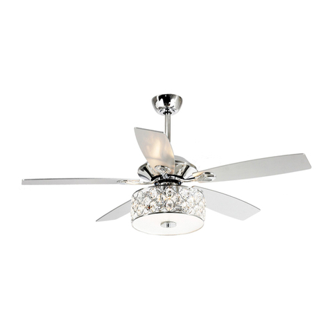
CEILING FAN
F6267220V
Installation & Operating Instructions for the
Parrotuncle Owner's Installation ,Manual
WARNING: SHUT POWER OFF AT FUSE OR CIRCUIT BREAKER
1
1. Proceed with caution. Read all instructions before beginning the installation.
2. WARNING! This fan may be operated only with a 2-pole switch with a 3mm contact opening
each.
3. Only an authorized electrician should execute the installation.
4. The installation height, i.e. the distance between the blades and the floor, should be at least
2.3 m.
5. Always maintain the distance between the lamp and inflammable materials (curtains,
wall, etc.), as indicated on the pictogram.
6. Make sure the fan is securely fastened at the ceiling.
7. WARNING! Do not use a dimmer type switch to control the fan speed.
8. WARNING! To prevent injuries, make sure the blades are not bent and that there are no
objects with in the area of rotation.
9. WARNING! Due to European safety regulations, if the flush mount option is elected, the fan
must not be re-installed utilizing the downrod. If attempted, this may cause a serious injury.
When assembling the fan, please follow your local safety regulations.
10. WARNING: Do Not use this fan in the same room at the same time as a gas or fuel burning
fire, unless the flue has been tested under these conditions of use by a competent person.
11. This appliance can be used by children aged from 8 years and above and persons with
reduced physical, sensory or mental capabilities or lack of experience and knowledge if they
have been given supervision or instruction concerning use of the appliance in a safe way
and understand the hazards involved. Children shall not play with the appliance. Cleaning
and user maintenance shall not be made by children without supervision.
12. Suitable for use indoors.
13. Before disassembling light kit, make sure the power supply is disconnected from the main
supply. Power supply can be on only after installation is completed.
14. The lampshade should not be removed from the light bulb when the power supply is on.
15. Replacement of light bulb is only possible when the light kit has cooled down, and the
power supply is disconnected from the main supply.
16. Make sure the lampshade is in the fixed position when operating the product.
17. Means for all poles disconnection having a contact separation that provide full discon
nection under over voltage category III conditions must be incorporated in the fixed wiring
in accordance with national wiring rules.
18. The fan is designed for indoor use. It is not designed for installation in a bathroom or any
damp area. Please ensure that the lamp does not come into contact with water.
READ AND SAVE THESE INSTRUCTIONS
WARNING: TO REDUCE THE RISK OF FIRE, ELECTRIC SHOCK,
OR INJURY TO PERSONS, OBSERVE THE FOLLOWING:
WARNING: SHUT POWER OFF AT FUSE OR CIRCUIT BREAKER
2
F6267220V
Installation & Operating Instructions for the
Parrotuncle Owner's Installation ,Manual
Thank you for purchasing this quality product.
To ensure correct function and safety, please read and save all instructions before using the product
Balanced parts package(1PCS)
Pls check whether above accessories are completed or not?Yes,and install.
REMOTE CONTROL(1PCS)
Installation & Operating Instructions for the
Parrotuncle Owner's Installation ,Manual
WARNING: SHUT POWER OFF AT FUSE OR CIRCUIT BREAKER
4" Ball / downrod assembly
Blades(4pcs)
Crystal cage cover
3g
3g
3g
Hardware package (1 set)
3
X13
F6267220V
WARNING: SHUT POWER OFF AT FUSE OR CIRCUIT BREAKER
Installation & Operating Instructions for the
Parrotuncle Owner's Installation ,Manual
1
x2x2
6
5
34
washers
Outlet box
3
Screws
4
Drill two mounting holes in the ceiling joist and securely screw the
mounting bracket to the ceiling using the washers and wood
screws provided. The mounting plate should be able to hold a
weight of at least 15.9kgs (35 lbs).
NOTE - Proper care must be taken when mounting to concrete
ceilings. For safe mounting, these ceilings may require stronger
screws and plastic plugs or anchors than supplied with the
product.
2
F6267220V
WARNING: SHUT POWER OFF AT FUSE OR CIRCUIT BREAKER
Installation & Operating Instructions for the
Parrotuncle Owner's Installation ,Manual
8
9
7
B
A
5
1
2
3
AC POWER IN PUT
TO FAN WIRES
L
N
F6267220V
10
Remove the 3 screws shown as above figure
before taking down the top housing .
11
WARNING: SHUT POWER OFF AT FUSE OR CIRCUIT BREAKER
Installation & Operating Instructions for the
Parrotuncle Owner's Installation ,Manual
Blade screws
and Washers
Coupler Cover
Yoke Screws
Fan Blade
Support Rod
Safety Pin
Top Plate
Center Band
Locate 12pcs blade attchment
screws and washers in hardware
pack. Slide blade through center
band and align holes. Insert 3pcs
blade screws and washers with
fingers. Tighten securely with a
phillips screwdriver. Repeat for the
remaining blades.
6
F6267220V
(WINTER TIME)
(SUMMER TIME)
d
A.warm weather-(Forward) A Downward airflow creates a cooling effect.
This allows you to set your air conditioner on a higher setting without
affecting your comfort.
B.Cool weather-(Reverse) An upward airflow moves warm air off the
ceiling.This allows Reverse you to set heating unit on a lower setting
without affecting your comfort.
reverse switch
The reverse switch contorls the direction of the blades.
WARNING: SHUT POWER OFF AT FUSE OR CIRCUIT BREAKER
Installation & Operating Instructions for the
Parrotuncle Owner's Installation ,Manual
7
F6267220V
Rotate 3* E12 bulbs into the
lamp holders . Attach the light
kit cage to the light kit plate
using the 4 screws .
Align the tooth hole on the light
plate with the hole on the crystal
cage cover, and tighten screw.
WARNING: SHUT POWER OFF AT FUSE OR CIRCUIT BREAKER
Installation & Operating Instructions for the
Parrotuncle Owner's Installation ,Manual
8
Remote controller
GENERAL INFORMATION
This remote controller is designed to separately control your ceiling fan speed and light ON/OFF.
There are four buttons (HI, MED, LOW, OFF) to control the speed of the fan and off.
The light button will control the light on and off.
The red indicator on the transmitter will light when one of the nine buttons is pressed.
INSTRUCTION OF INSTALLATION AND OPERATION
2.INSTALLING RECEIVER IN CEILING FAN
A. Safety precautions:
WARNING: HIGH VOLTAGE! Disconnect power by
removing fuse or switching off circuit breaker.
Do not use with solid state fans.
Electrical wire must meet all local and national
electrical code requirements.
Supply for fan must be 220/240 volt, 50Hz. Maximum
fan motor amps: 1.0, Maximum light watts: 180
incandescent or ballast.
Otherwise power can cause serious injury or death.
B. Installing receiver in fan:
a. emove power from the circuit.
b. emove ceiling fan canopy from the mounting
bracket.
c. isconnect existing wiring between ceiling fan and
Supply in electrical junction box.
d. ake connections as follows, using the wire nuts
supplied:
For Mounting Controller, Model RE-026
CONNECT TO
Green fan wire ....Bare supply wire
Brown receiver wire(AC IN L) ....Brown supply wire
Blue receiver wire(AC IN N) ....Blue supply wire
Blue receiver wire(TO MOTOR N) ....Blue fan wire
Brown receiver wire(TO MOTOR L) ....Brown fan wire
Black/Orange receiver wire(FOR LIGHT) ....Black/Orange light wire
CAUTION: Ceiling Angle Shall Not Exceed 30 Degrees,
FIG1
ACN
ACL
ANT
COM FAN LIGHT
INPUT
OUTPUT
RECEIVER
Use wire connecting nuts supplied with the fan
(FIG.3)
FROM POWER SOURCE
AC 220~240 VOLT 50Hz
.
Use wire connecting nuts
supplied with the remote
controller.
WIRE NUT
RECEIVER
CANOPY
(FIG.4)
ANTENNA PUT AT OUTSIDE
OF CANOPY BOX CAN GET
MORE OPERATION
DISTAN CE
BLUE
INPUT
OUTPUT
BROWN
ANT
CANOPY
RECEIVER
BLUE
BROWN
BLACK OR ORANGE
1.SETTING THE CODES
To set the codes, perform the following steps:
A. Setting the codes on the transmitter:
a. emove battery cover. Press firmly on the arrow and slide battery cover off.
b. lide code switches to your choice of up or down position. (Factory setting is all up. Do not use this position. Use a
Small screwdriver or ball point pen to slide firmly up or down (Figure 1)).
B. Setting the codes on the receiver:
The Learn Key must be pressed with in 30 seconds, after pressing the Power button.
If not, please press the Power button to restart.
Keep pressing the button learn key in excess of 3 second it becomes a LEARN status.
The receiver can remember the last codes status .The light flash two times.
TRANSMITTER
LEARN CODE
COM
COD E
F6267220V
WARNING: SHUT POWER OFF AT FUSE OR CIRCUIT BREAKER
Installation & Operating Instructions for the
Parrotuncle Owner's Installation ,Manual
9
If other fans or supply wires are different color, have this unit installed by qualified licensed electrician.
e. ush all connected wires up into junction box.
f. ay the brown antenna wire on top of the receiver, and put the receiver into the mounting bracket.
g. einstall the canopy on the mounting bracket.
h. estore power.
3. PERATING TRANSMITTER:
A. Install 1.5 volt battery(not included). (To prevent damage to transmitter, remove the battery if not used for a long time).
B. Store the transmitter away from excessive heat or humidity.
C. This remote control unit is equipped with roll code combinations. In order to prevent possible interference from or to
other remote units such as garage door openers, car alarm or security system. If you find that your fan and light kit go
on and off without using your remote control, simply change the code combination in your transmitter and receiver.
D. Operating the buttons on the panel of the transmitter.
3 key -for fan high speed.
2 key-for fan medium speed.
1 key-for fan low speed.
OFF key-for fan off.
LIGHT key-for light ON/OFF.
2hr , 4hr , 8hr button to set the FAN sleep timer from
YOUR REMOTE NOW HAS FULL CONTROL OF THE FAN AND LIGHT.
OPERATION DISTANCE 20 FEET
TRANSMITTER
MODEL:
RE-011
Optional Wall Mounting for Transmitter Holder
Place in accessible area of your home, and screw the
transmitter holder into wall using the two screws
provided, slide hand unit into holder.
4. TROUBLE SHOOTING GUIDE
1. ails to operate
a. ower to receiver ?
b. eceiver wired correctly ?
c. an manual speed control in highest position ?
d. ight kit switch turned on ?
e. ood battery in the transmitter ?
f. ode set at exact same positions in both transmitter and receiver ?
2. on't operate at distance
If transmitter operates fan/light kit when up close, but not at 20 feet away.
Try placing the brown antenna wire higher, up through ceiling/outside the junction box.
NOTICE !
Your ceiling fan and light kit assembly must meet the following requirements:
1. o not use with solid state fans.
2. lectrical rating: 220V~240V 50Hz
MAX. Motor amps: 1.0
MAX. Light watts: 180-(incandescent, or ballast non-dimmer, or LED)
WARNING
TO REDUCE THE RISK OF SHOCK, THIS FAN MUST BE INSTALLED WITH A WALL CONTROL/SWITCH.
LR03 1.5V AAA
LR03 1.5V AAA
F6267220V
WARNING: SHUT POWER OFF AT FUSE OR CIRCUIT BREAKER
size of product
Installation & Operating Instructions for the
Parrotuncle Owner's Installation ,Manual
10
F6267220V
52in
WARNING: SHUT POWER OFF AT FUSE OR CIRCUIT BREAKER
Table of Contents
1. Fan
/ Remote is not working
2. Fan is noisy
3.
Fan Wobbles
4. Light is not working
Please refer to the instruction sheet for detailed directions and descriptions of
installation steps and requirements.
1. FAN / REMOTE IS NOT WORKING
Ensure the remote is within the 20
foot range of the receiver
To reset the remote control: 1) Turn off power to fan
using the wall switch or circuit breaker. 2) Remove baeries from remote.
3) Wait 10 seconds. 4) Replace baeries and turn power on
Check baeries to
insure they are good and oriented correctly
Check to make sure the frequency switches (DIP Switches) from the remote to the receiver are set to the same frequency
Check the main and branch circuit fuses or breakers
If using a Variable Speed Wall Switch, ensure
it is specifically designed for use with a ceiling fan.
Check the line wire connecons to the fan and the
switch wire connecons in the switch housing per the instrucons
If fan sll does not work, please contact Customer Service Support@parrotuncle.com
2. THE FAN IS NOISY
Make sure all motor housing screws are ghtened
Make sure the screws that aach fan blade to motor are ght
Make sure the wire nut connectors are not raling against each other or the interior wall of the switch housing
Allow 24-hour break in period. Most noises associated with the new fan may disappear during this me
If using a ceiling light kit, make sure the glassware is secured ghtly
Make sure there is a short distance/gap from the ceiling to the top of the canopy. The canopy
should not touch the ceiling!
Make sure your ceiling box is secure and that the rubber isolator pads are used between the mounng bracket and outlet box
TROUBLESHOOTING GUIDE
Installation & Operating Instructions for the
Parrotuncle Owner's Installation ,Manual
11
F6267220V
WARNING: SHUT POWER OFF AT FUSE OR CIRCUIT BREAKER
3. THE FAN WOBBLES
Verify all blades and blade bracket screws are secure (most fan wobble problems are caused by loose parts). Once fan is properly
installed, run the ceiling fan for 10 minutes to let the fan self-adjust.
If wobble occurs aer running the fan for 10 minutes, verify blade level using the following process:
a)
select a point on the ceiling above the p of one of the blades. Then select the fan blade and measure from the center
of the selected blade to point on the ceiling. Rotate the fan unl the next blade is posioned and repeat the
measurement using the same point from the ceiling for every blade. Measurements
should be within 1/8 inch.
b) If all deviaon are less than 1/8 inch and the fan continues to wobble, please contact Customer Service Support@parr
otuncle.com to order a complimentary Blade Balancing Kit
- If all deviaons are less than 1/8 inch and the fan connues to wobble, please contact Customer Service Support@parrotuncle
.com to order a complimentary Blade Balancing Kit
4.
LIGHT IS NOT WORKING
Check Bulb to make sure it is installed correctly
Remove non-working bulb and replace with a bulb that is known to be a good working bulb
To reset the remote control: 1) Turn off power to fan using the wall switch or circuit breaker. 2) Remove baeries from
remote. 3) Wait 10 seconds. 4) Replace baeries and turn power on
Installation & Operating Instructions for the
Parrotuncle Owner's Installation ,Manual
12
F6267220V
AFTER INSTALLATION
The fan blades have been adjusted in the factory to minimize any wobble
NOTE:CEILING FANS TEND TO MOVE DURING OPERATION DUE TO THE FACT THAT THEY
ARE MOUNTED ON A RUBBER CROMMET. IF THE FAN WAS MOUNTED RIGIDLY TO THE
CEILING, IT WOULD CAUSE EXCESS VIBRATION. MOVEMENT OF A FEW CENTIMENTERS
IS QUITE ACCEPTABLE AND DOES NOT SUGGEST ANY PROBLEM
WOBBLE”
TO REDUCE THE FAN WOBBLE: PLEASE CHECK THAT ALL SCREWS WHICH SECURED THE MOUNTING
BRACKET AND DOWNROD ARE SECURE.
BALANCING A WOBBLING CEILING FAN:
For your convenience, a Balancing Kit is included; please follow this procedure when balancing the fan:
1.Check that all blade and blade arm screws are secure.
2.Most fan wobbling problems are caused when blade levels are unequal. Check this level by
selecting a point on the ceiling above the tip of one of the
blades. Measure this distance.Rotate the fan until the next blade is positioned for
measurement. Repeat for each blade. The distance deviation should be equal within
1/8"(0.32cm).
3.Use the enclosed Blade Balancing Kit if the blade
wobble is still noticeable.
4.If the blade wobble is still noticeable, interchanging two
adjacent (side by side) blades can redistribute the weight and possibly result in smoother
operation. WARNING: TO REDUCE THE RISK OF PERSONAL INJURY, DO NOT BEND THE
BLADE ARM WHILE INSTALLING, BALANCING THE BLADES, OR CLEANING THE FAN. DO
NOT INSERT FOREIGN OBJECTS BETWEEN ROTATING FAN BLADES.
NOISE
When it is quiet(especially at night) you may hear occasional small noises. This is normal. Please allow
a 24-hour “breaking-in” period, most noises associated with a new fan disappear during the time.
CARE AND CLEANING
1.Periodic cleaning of your ceiling fan is the only maintenance required. Use a soft brush or lint free cloth to
avoid scratching the paint finish. Please make sure to turn off electricity power before you clean your fan
2.Do not use water when cleaning your ceiling fan. It could damage the motor or the blades
and create the possibility of an electrical shock.
3.Motor has permanently lubricated ball bearing. No need to oil
NOTE: MAKE SURE THE POWER IS OFF AT THE ELECTRICAL PANEL BOX BEFORE YOU
ATTEMPT ANY CLEANING OR REPAIRS.
WARNING: SHUT POWER OFF AT FUSE OR CIRCUIT BREAKER
Installation & Operating Instructions for the
Parrotuncle Owner's Installation ,Manual
13
F6267220V

Other Parrot Uncle Fan manuals

Parrot Uncle F6276110V Manual

Parrot Uncle

Parrot Uncle F6276110V Manual

Parrot Uncle F6306 Manual

Parrot Uncle

Parrot Uncle F6306 Manual

Parrot Uncle F6288 User manual

Parrot Uncle

Parrot Uncle F6288 User manual

Parrot Uncle BBLAB025A0 Manual

Parrot Uncle

Parrot Uncle BBLAB025A0 Manual

Parrot Uncle F4707Q110V User manual

Parrot Uncle

Parrot Uncle F4707Q110V User manual

Parrot Uncle F6252BK Manual

Parrot Uncle

Parrot Uncle F6252BK Manual

Parrot Uncle F6299BK Manual

Parrot Uncle

Parrot Uncle F6299BK Manual

Parrot Uncle F6287 User manual

Parrot Uncle

Parrot Uncle F6287 User manual

Parrot Uncle F6279 Manual

Parrot Uncle

Parrot Uncle F6279 Manual

Parrot Uncle F6215 Manual

Parrot Uncle

Parrot Uncle F6215 Manual

Parrot Uncle F6293110V Manual

Parrot Uncle

Parrot Uncle F6293110V Manual

Parrot Uncle F6216 Manual

Parrot Uncle

Parrot Uncle F6216 Manual

Parrot Uncle F4701 User manual

Parrot Uncle

Parrot Uncle F4701 User manual

Parrot Uncle BBLAB011A User manual

Parrot Uncle

Parrot Uncle BBLAB011A User manual

Parrot Uncle F6298 Manual

Parrot Uncle

Parrot Uncle F6298 Manual

Parrot Uncle F8225110V User manual

Parrot Uncle

Parrot Uncle F8225110V User manual

Parrot Uncle F3501 Manual

Parrot Uncle

Parrot Uncle F3501 Manual

Parrot Uncle F6236 Manual

Parrot Uncle

Parrot Uncle F6236 Manual

Parrot Uncle F4503 Manual

Parrot Uncle

Parrot Uncle F4503 Manual

Parrot Uncle F6231 Manual

Parrot Uncle

Parrot Uncle F6231 Manual

Parrot Uncle BB530173SQ Manual

Parrot Uncle

Parrot Uncle BB530173SQ Manual

Parrot Uncle F6298NW-EU User manual

Parrot Uncle

Parrot Uncle F6298NW-EU User manual

Parrot Uncle F6292 User manual

Parrot Uncle

Parrot Uncle F6292 User manual

Parrot Uncle F6272110V Manual

Parrot Uncle

Parrot Uncle F6272110V Manual

Popular Fan manuals by other brands

Broan SMD6 installation instructions

Broan

Broan SMD6 installation instructions

Craftmade AT52 installation guide

Craftmade

Craftmade AT52 installation guide

Ellington DUN52PLN5 installation guide

Ellington

Ellington DUN52PLN5 installation guide

Kichler Lighting Larissa instruction manual

Kichler Lighting

Kichler Lighting Larissa instruction manual

Living & Co YF-ST1638 instruction manual

Living & Co

Living & Co YF-ST1638 instruction manual

Casablanca 59360 Owner's guide and installation manual

Casablanca

Casablanca 59360 Owner's guide and installation manual

Dustcontrol RAF 2501 Original instructions

Dustcontrol

Dustcontrol RAF 2501 Original instructions

Ellington CEN54BCH5 installation guide

Ellington

Ellington CEN54BCH5 installation guide

Alpine BPRPHP14 Series Installation and maintenance instructions

Alpine

Alpine BPRPHP14 Series Installation and maintenance instructions

Kutzner + Weber RSD Series installation instructions

Kutzner + Weber

Kutzner + Weber RSD Series installation instructions

Fanimation FLORID LP8300 Series instruction manual

Fanimation

Fanimation FLORID LP8300 Series instruction manual

CellarPro 3000Scmr-EC owner's manual

CellarPro

CellarPro 3000Scmr-EC owner's manual

Eberg HUX 40 instruction manual

Eberg

Eberg HUX 40 instruction manual

Progress Lighting Airpro P250073 installation manual

Progress Lighting

Progress Lighting Airpro P250073 installation manual

S&P MBE-R manual

S&P

S&P MBE-R manual

Lasko S18610 operating manual

Lasko

Lasko S18610 operating manual

Canarm DUAL MOUNT SERIES installation instructions

Canarm

Canarm DUAL MOUNT SERIES installation instructions

Emerson CAMDEN CF3600AP owner's manual

Emerson

Emerson CAMDEN CF3600AP owner's manual

manuals.online logo
manuals.online logoBrands
  • About & Mission
  • Contact us
  • Privacy Policy
  • Terms and Conditions

Copyright 2025 Manuals.Online. All Rights Reserved.