Parsec Srl GOLDEN RETRIEVER User manual

GOLDEN RETRIEVER
Installation Instructions
e Golden Retriever is a portable, ruggedized case with a high
performance 5 in 1 Parsec antenna built into the lid. It is available with
MIMO LTE, MIMO WiFi, and GPS. is compact, portable oce in
a box is perfect for a wide variety of mobile communications. Add a
wireless router and battery and this Golden Retriever case antenna will
provide on the go connectivity wherever you are. Designed to operate
roughly up to 5 simultaneous devices at once.
REQUIRED TOOLS
REQUIRED ACCESSORIES (PRO5GR2L2WG-L OR PRO5GR2L2WG-A)
REQUIRED ACCESSORIES (PRO5GR2L2WG-G1 OR PRO5GR2L2WG-G2)
Ethernet Cords: 2pc (Length as required by the customer)(Not required for A version)
Ethernet Cords: 2pc (1pc for G1 version. Length as required by the customer)
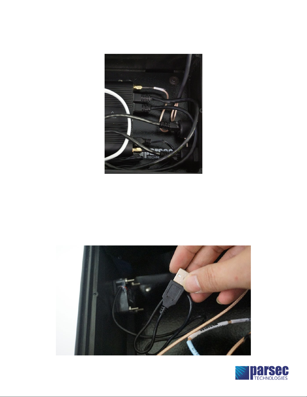
USB Cords: 1 pc (Length as required by customer. Only for G2 version)
Cradlepoint 2x2 Power to Barrel Adapter (Part #170665-000)
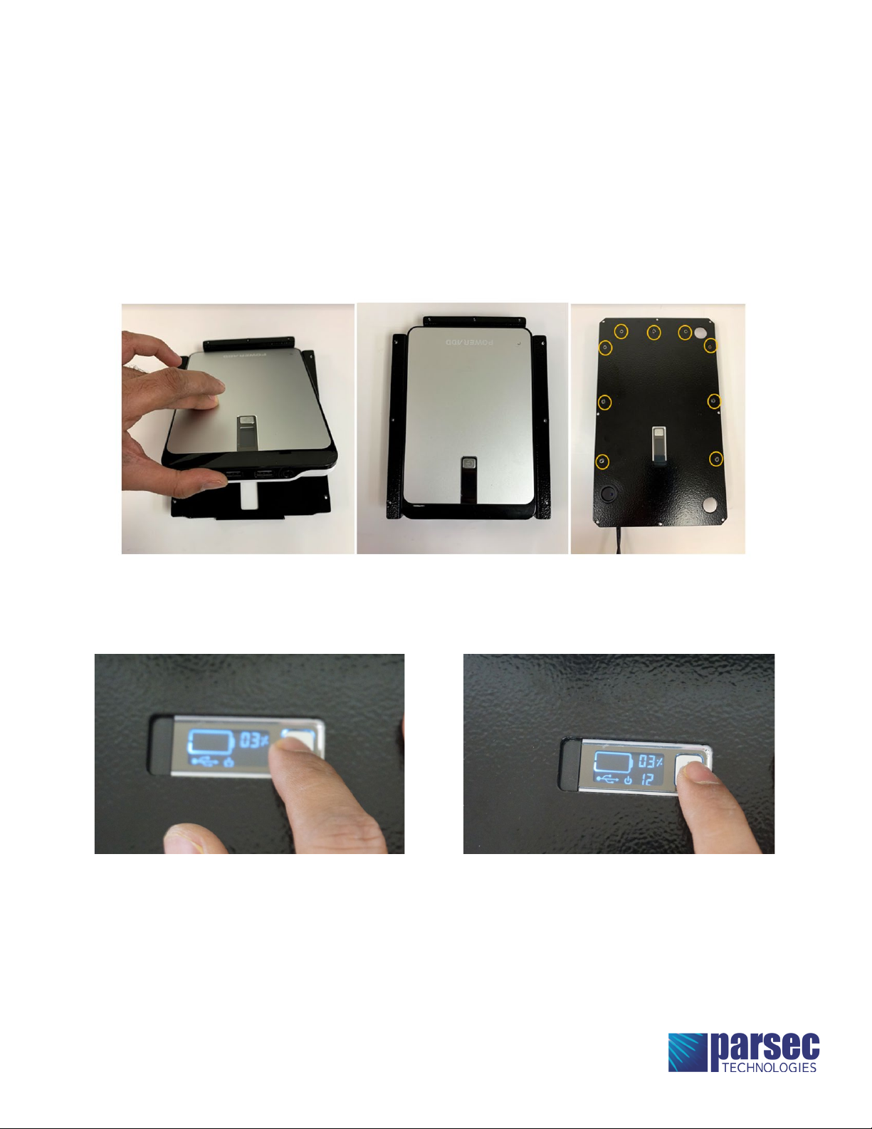
Battery: PowerAdd Pilot Pro 2 23000mAH Portable Battery Charger
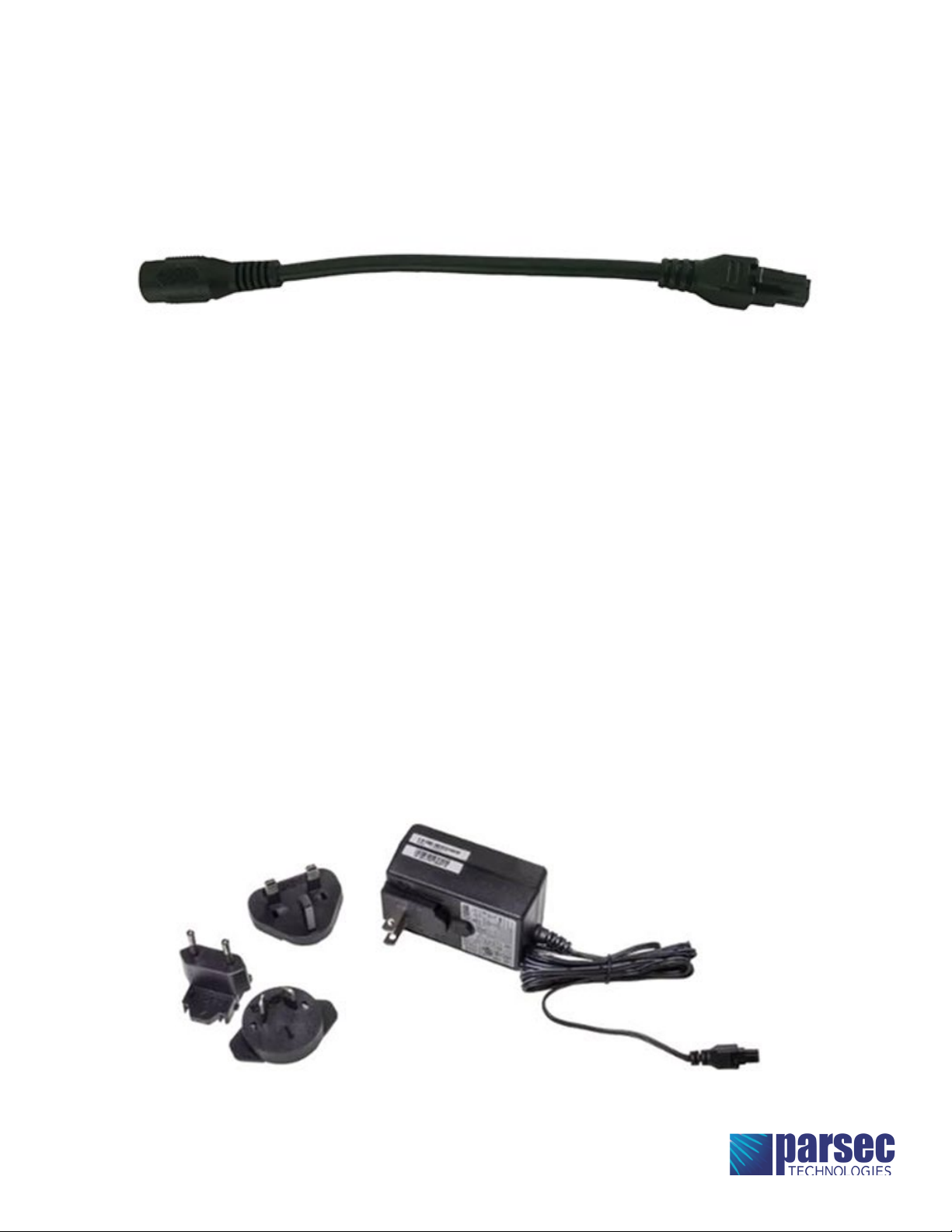
Power Supply (required for router)
Extension Cord (NEMA 5-15 Plug to NEMA 5-15 Socket)
Electronic Equipment Power Cord (NEMA 5-15 Plug x IEC C13 Socket, SVT)
Phillips Screwdriver
Router (select one of the following routers.)
• CRADLEPOINT IBR900-1200M
• CRADLEPOINT IBR600
• INSEEGO SKYUS 160
• SIERRA WIRELESS AIRLINK RV55
• CRADLEPOINT IBR900-1200M
• CRADLEPOINT IBR600
• INSEEGO SKYUS 160
• SIERRA WIRELESS AIRLINK RV55

Router Installation:
Step 1.
Step 2.
Step 3.
Check the power options available on the case.
- For PRO5GR2L2WG-G1 or PRO5GR2L2WG-G2: Install the battery on the top cover plate as directed in the “Router Power
Options” step.
- For PRO5GR2L2WG-L or PRO5GR2L2WG-A: No Battery Option.
Install an activated SIM into the Router.
Thread the cables through the top cover plate. Make sure to not bend the cables when closing the box. (Figure 1)
FIGURE 1

Step 4.
Connect the Antenna cables to the router. Clean all connectors so there is no dust in the terminals. Follow the chart to
connect the cables. (Figures 2-4)
FIGURE 2
FIGURE 4
FIGURE 3

Step 5. (PRO5GR2L2WG-G1 OR PRO5GR2L2WG-G2)
Step 6. (PRO5GR2L2WG-L OR PRO5GR2L2WG-A)
Use the Cradlepoint 2x2 Power to Barrel Adapter to connect the router to the battery. Connect one of the switch’s barrel
connector to the battery and the other to the cradlepoint 2x2 power to barrel adapter. (Figure 5)
Choose the correct AC power supply unit for the router and connect it to the router. (Figure 6 & 15)
FIGURE 5
FIGURE 6

Step 7.
All cables connected to the router
Mount the router onto the router mount plate. Match the holes on the router to the holes on the base plate. Fasten the
router using the four 1/4-20, 1/4 inch screws provided in the kit. (Figure 7)
FIGURE 7

Router and Case connection Instructions:
All connections diagram

Step 1.
Step 2. (PRO5GR2L2WG-G2 ONLY)
Step 3.
There are two RJ-45 ports for G2 and L versions and one for the G1 version of the case. Choose which port you want to
use for WAN and LAN connectors. Connect one end of the ethernet cords from the router to the RJ-45 ports on the case.
(Figure 8)
There is one USB port on the case which can be used for charging electrical devices. For charging electrical devices,
connect the USB port on the case to the USB port on the battery.
Connect the fan USB port on the case to the USB ports on the router. (Figure 9)
FIGURE 8
FIGURE 9

Step 1.
Step 2.
Step 4.
Step 5.
PRO5GR2L2WG-G1 and PRO5GR2L2WG-G2 have the option of a battery.
Insert the battery in the battery tray. (Figure 10)
Place the top cover plate on the battery tray and fasten the battery tray to the top cover plate using nine 4-40, ¼” inch
at head screw provided in the kit. (Figure 11)
Connect the power supply unit of the router to the battery OUTPUT port with the DC barrel to DC barrel extension cord
provided with the battery.
Connect the DC adapter installed on the case to the DC charging port on the battery. To charge the battery, use the
charger provided with the battery and connect the DC barrel plug on the charger to the case.
Parsec provides a battery tray for PowerAdd Pilot Pro 2 23000mAH Portable Battery Charger. For installing the battery
follow the instructions below.
FIGURE 10
Router Power Options:
FIGURE 11
Step 3.
Set the battery to supply 12V by pressing and holding the power button for 5 seconds until you see the volts on the
screen. Press the button again to set it to 12V. (Figure 12 & 13)
FIGURE 13
FIGURE 12

Step 6.
Step 7.
Connect the USB port on the case to the battery using the USB cord.
Turn ON the power switch to turn the router on. (Figure 14)
FIGURE 14
FIGURE 15
PRO5GR2L2WG-L and PRO5GR2L2WG-A come with an AC adapter with 16-inch extension cord.
Parsec provides an AC adapter mounted on the case for L and A version. For powering the router with AC adapter
follow the instructions below.
Step 1.
Step 2.
Connect the AC adapter of the Power supply unit to the AC adapter on the case using an extension cord.
Connect the IEC C13 Socket end of the Electronic Equipment Power Cord (NEMA 5-15 Plug x IEC C13 Socket, SVT) to the
case and the other end to the wall to turn on the router. (Figure 15)

Antenna Operation:
Step 1.
Step 2.
Step 3.
Make sure all cables are properly connected. Check all of the connections and make sure there is no loose
connections.
Before turning on the antenna, always snap the fan and vent caps open. (Figure 16)
Turn on the power source of the router.
PRO9SB4L4WG-L and PRO9SB4L4WG-A : Connect IEC C13 Socket end of the Electronic Equipment Power Cord (NEMA
5-15 Plug x IEC C13 Socket, SVT) to the case and the other end to the wall to turn ON the router. Then Turn ON the power
source. the router will turn ON and the display lights will start blinking.
PRO5GR2L2WG-G1 and PRO5GR2L2WG-G2: Turn on the main power switch of the battery and turn on the power switch
on the top cover plate.
FIGURE 16

Step 4.
Step 5.
Step 6.
Connect a network cable between the ethernet ports on a computer and one of the ethernet ports on the antenna
enclosure. Make sure you are connected to a LAN port and not a WAN port.
Bring up a web browser on the computer and type 192.168.0.1 into the address bar. You should see the Cradlepoint login.
(Figure 17)
Type the username and password. Username is “admin” by default. The password can be found on the information
cutout on the router. (Figure 18)
FIGURE 17
FIGURE 18

parsec-t.com
CAUTION
To comply with FCC RF Exposure requirements in section 1.1310
of the FCC Rules, antennas used with this device must be installed
to provide a separation distance of at least 20 cm from all persons to
satisfy RF exposure compliance.
DO NOT
- Operate the transmitter when someone is within 24 inches of
the antenna.
- Install antenna or mast assembly on a windy day
- Install the mast close to power lines as it can cause serious injuries
or death.
WARNING
is document gives the detailed instructions to install an antenna to
the best of our knowledge. is document if for general information
only. It cannot be used as a warranty. Parsec Technologies, Inc. will
not accept any liability for any damage caused by an antenna due to
unknown variables.
Make sure the fan cap covers are open while using the antenna.
Install the sim in router before mounting on to the router mount plate.
Warnings:
Step 7.
Step 8.
In the router, click on Status, Internet, and then Connections in the dropdown menu. You should see options related to
SIM cards installed. Select the option with a cellular SIM. (Figure 19)
If all of the steps are completed, the antenna should be on and operating. Close the top cover plate using the thread
forming screws provided in the kit. (Figure 20)
FIGURE 19
FIGURE 20
This manual suits for next models
4
Table of contents
Popular Antenna manuals by other brands

Hemisphere GPS
Hemisphere GPS C321 user guide

MFJ
MFJ 1801 quick start guide

Cisco
Cisco Aironet AIR-ANT5160V-R user guide

MFJ Enterprises
MFJ Enterprises MFJ-948 instruction manual

Extreme Networks
Extreme Networks Extreme Wireless Site preparation and installation guide

TRENDnet
TRENDnet TEW-OA24D Specifications

One Forall
One Forall 17411 Quick installation guide

Zonet
Zonet ZWA2112 Product data

Matsing
Matsing MS-12.6DB180 instruction manual

Listen Technologies
Listen Technologies UNIVERSAL ANTENNA KIT LA-122 user manual

Philips
Philips SDW1420 Specifications

SteppIR
SteppIR BigIR - MK IV Vertical instruction manual