Ref. 11/494 PM2010 Ref. 11/494 PM2010
- PMS2000 System -- PMS2000 System -4 5
L'interruttore di rete "POWER" [4] è di tipo
funzionale; interrompe cioè la linea di distribuzione
della alimentazione a bassa tensione (24V, +15V
e -15V).
Il led "MAINS" [2] acceso segnala la presenza
della tensione di alimentazione da rete, pertanto
risulterà spento soltanto staccando il cavo di
alimentazione da rete o in caso di mancanza
della rete stessa.
Il collegamento di sicurezza a terra delle parti
metalliche del modulo e, conseguentemente, di
tutto il cestello, è effettuato per mezzo del cavo
di alimentazione fornito a corredo (vedere, a
riguardo, quanto riportato nel paragrafo 2.2,
"Note di sicurezza").
2.2 Note di sicurezza
Ogni intervento allinterno del cestello dei moduli o
sul modulo stesso, quale la selezione di alcuni modi
duso o lapplicazione di accessori, deve essere
effettuato solo da personale specializzato.
La rimozione del coperchio rende accessibili parti
con rischio di scosse elettriche.
Prima di accedere all'interno del cestello dei moduli
accertarsi sempre che il cavo di rete del modulo
alimentatore sia staccato.
Nel caso di accidentale caduta di liquidi
sullapparecchio, staccare immediatamente la
spina di rete ed interpellare il centro di
assistenza PASO più vicino.
Lapparecchio é corredato di cavo di alimentazione
con filo di terra ed il relativo terminale sulla spina
di rete non deve essere rimosso in alcun caso.
Assicurarsi che la presa di corrente sia dotata di
collegamento di terra a norma di legge.
Il morsetto di massa telaio [7] consente di
collegare altre apparecchiature per la sola funzione
di schermatura dei segnali a basso livello: questa
presa non deve essere utilizzata per il collegamento
di sicurezza del telaio alla terra.
Fig. 3.1 Fig. 3.2
Tabella 3.1.1
3. INSTALLAZIONE
Il modulo alimentatore deve essere installato nel
cestello esclusivamente nella posizione indicata
in fig. 3.1 seguendo le istruzioni di montaggio ad
esso allegate.
Una volta installato e fissato il modulo alimentatore
al cestello si dovrà provvedere a collegare la
piattina [A] del connettore di espansione [8]
all'apposita presa (particolare [B] di fig. 3.2) posta
sul circuito di connessione del cestello.
3.1 Connettore di espansione
Il connettore di espansione [8] permette di
estendere le capacità del sistema modulare fino
ad un massimo di tre cestelli (complessivi); a tale
connettore dovrà essere collegato il modulo di
espansione del cestello successivo.
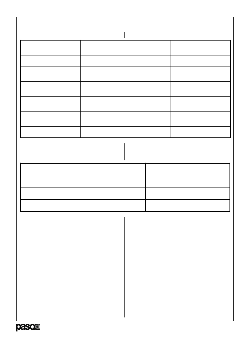
Nella tabella 3.1.1 sono riportate le connessioni
elettriche di questa presa.
PIN
1ingresso bus PA
2bus sinistro
3bus destro
4din-don
5SCL - clock seriale per I2C
6massa
7massa
8mute out
9SDA - dato seriale per I2C
Modulo alimentatore
Power supply module
The main power switch ("POWER") [4] is of the
functional type, that is to say it cuts off the
low-voltage (24V, +15V e -15V) power supply
distribution line.
The "MAINS" LED [2] lights up to indicate the
presence of the mains voltage, and it will therefore
only go OFF when the power-supply cable is
disconnected or in case of a mains failure.
The safety connection to earth of all the metal
parts of the module and, consequently, of the
whole card-cage, is made by means of the power-
supply cable included in the supply (on this subject,
refer to the contents of paragraph 2.2
"Notes on Safety").
2.2 Safety notes
Any work inside the module card-cage or on the
actual modules, such as selecting some of the
modes of operation or applying accessories may
only be carried out by specialised personnel.
On removing the cover, parts entailing a danger
of electric shocks will be made accessible.
Always make sure that the mains cable of the
power-supply module is disconnected before
accessing the inside of the module card-cage.
If any liquid is accidentally spilt on the equipment,
disconnect the mains cable immediately and
contact the nearest PASO Servicing Centre.
The equipment is supplied with its own power-
supply cable with an earth wire. The relevant
terminal on the mains plus must never be removed,
under any circumstances.
Make sure that the power outlet has a connection
to earth in accordance with the law.
The frame ground terminal [7] makes it
possible to connect other equipment for the sole
purpose of shielding low level signals. This socket
must never be used for the safety connection of
the frame to earth.
3. INSTALLATION
Inside the card cage, the power supply module
must always be installed only in the position
indicated in Figure 3.1, following the mounting
instructions attached to it.
Once the power supply module has been installed
inside the card-cage and secured to it, the flat
cable [A] of the expansion connector [8] must be
connected to the socket provided for this purpose
(detail [B] in Figure 3.2) positioned on the card-
cage connection circuit.
3.1 Expansion Connector
The expansion connector [8] can be used to
expand the capacity of the modular system up
to a maximum of three card-cages (total). The
expansion module of the next card-cage has to
be connected to this connector.
Table 3.1.1 shows the pin-out for the electrical
connections of this socket.
PIN
1PA input bus
2left bus
3right bus
4chime
5SCL - serial clock for I2C
6earth
7earth
8mute out
9SDA - serial datum for I2C
Table 3.1.1
A
B