NGI N36100 Series User manual
Hunan Next Generation Instrumental T&C Tech. Co., Ltd.
NGI lNGI N36100 Series Wide Range Programmable DC Power Supply
N36100 Series Wide Range
Programmable DC Power Supply
User Manual
©Copyright Hunan Next Generation Instrumental T&C Tech. Co., Ltd.
Version: V20210606

Hunan Next Generation Instrumental T&C Tech. Co., Ltd.
NGI lNGI N36100 Series Wide Range Programmable DC Power Supply
Contents
CONTENTS...................................................................................................................... 0
1 PREFACE.......................................................................................................................2
2 SAFETY INSTRUCTIONS............................................................................................... 3
2.1 Safety Notes......................................................................................................3
2.2 Safety Symbols..................................................................................................3
3 PRODUCT.....................................................................................................................4
3.1 Brief Introduction............................................................................................. 4
3.1.1 Features................................................................................................. 4
3.2 N36100 Series Lineup....................................................................................... 5
3.3 Appearance & Dimension.................................................................................5
3.4 Package Contents and Accessories...................................................................6
3.5 Default Communication Parameter..................................................................7
4 PANEL INTRODUCTION............................................................................................... 8
4.1 Front Panel Introduction.................................................................................. 8
4.1.1 Screen.................................................................................................... 8
4.1.2 Button....................................................................................................9
4.2 Rear Panel Introduction..................................................................................10
4.2.1 Output Interface.................................................................................. 11
4.2.2 Four-wire Interface..............................................................................11
4.2.3 LAN Port...............................................................................................11
4.2.4 RS232 Interface................................................................................... 12
4.2.5 RS485/CAN Interface........................................................................... 12
4.2.6 AC Power Socket..................................................................................12
4.2.7 Grounding Screw................................................................................. 13
5 POWER-ON TEST....................................................................................................... 14
5.1 Power-on Inspection...................................................................................... 14
5.1.1 Connection and Setting....................................................................... 14
5.1.2 Switch-on............................................................................................. 14
5.2 Output Inspection.......................................................................................... 15
5.2.1 Output Voltage Inspection.................................................................. 15
5.2.2 Output Current Inspection.................................................................. 15
6 LOAD CONNECTION.................................................................................................. 16
6.1 Load Wire....................................................................................................... 16
6.2 Maximum Allowable Current......................................................................... 16
6.3 Effect of Noise and Impedance...................................................................... 16
6.4 Inductive Load................................................................................................ 17

Hunan Next Generation Instrumental T&C Tech. Co., Ltd.
NGI lNGI N36100 Series Wide Range Programmable DC Power Supply
6.5 Local Sense and Remote Sense...................................................................... 17
6.5.1 Local Sense.......................................................................................... 18
6.5.2 Remote Sense...................................................................................... 18
6.6 Load Connection.............................................................................................19
7 OPERATION............................................................................................................... 20
7.1 Menu.............................................................................................................. 20
7.2 V/I................................................................................................................... 21
7.3 SEQ Edit.......................................................................................................... 22
7.3.1 Parameter Setting................................................................................23
7.4 SEQ Test.......................................................................................................... 23
7.5 CP....................................................................................................................25
7.6 APG Analog Programming (Optional).............................................................26
7.7 Protection....................................................................................................... 27
7.8 System............................................................................................................ 28
7.9 CV/CC Priority Function.................................................................................. 30
7.9.1 CV Priority Mode................................................................................. 31
7.9.2 CV Priority Mode................................................................................. 32
8 REMOTE OPERATION................................................................................................ 34
8.1 LAN Port..........................................................................................................34
8.2 Connection to Computer................................................................................ 35
9 MAINTENANCE AND SELF-INSPECTION....................................................................36
9.1 Regular Maintenance..................................................................................... 36
9.2 Fault Self-inspection....................................................................................... 36
10 MAIN TECHNICAL DATA.......................................................................................... 37
11 APPENDIX................................................................................................................ 40
11.1 Protection Display List.................................................................................. 40
11.2 Communication Interface.............................................................................40
11.3 Recommended Wire Gauge Selection Table................................................ 41
11.4 Trouble Shooting.......................................................................................... 41
Hunan Next Generation Instrumental T&C Tech. Co., Ltd.
NGI lNGI N36100 Series Wide Range High Voltage Programmable DC Power Supply
2
1 Preface
Dear Customers,
First of all, we greatly appreciate your choice of N36100 series DC power supply
(N36100 for short). We are also honored to introduce our company, Hunan Next
Generation Instrumental T&C Tech. Co., Ltd.( NGI for short).
About Company
NGI is a professional manufacturer of intelligent equipment and test & control
instruments, committed to developing, manufacturing battery simulators, power
supplies, electronic loads, and many more instruments. The products can be widely
used in the industries of battery, power supply, fuel cell, consumer electronics, new
energy vehicle, semiconductor, etc.
NGI maintains close cooperation with many universities and scientific research
institutions, and maintains close ties with many industry leaders. We strive to
develop high-quality, technology-leading products, provide high-end technologies,
and continue to explore new industry measurement and control solutions.
About User Manual
This manual is applied to N36100 series DC power supply, including installation,
operation, specifications and other detailed information. The copyright of the
manual is owned by NGI. Due to the upgrade of instrument, this manual may be
revised without notice in future versions.
This manual has been reviewed carefully by NGI for the technical accuracy. The
manufacturer declines all responsibility for possible errors in this operation manual,
if due to misprints or errors in copying.The manufacturer is not liable for
malfunctioning if the product has not correctly been operated.
To ensure the safety and correct use of N36100, please read this manual carefully,
especially the safety instructions.
Please keep this manual for future use.
Thanks for your trust and support.
Hunan Next Generation Instrumental T&C Tech. Co., Ltd.
NGI lNGI N36100 Series Wide Range High Voltage Programmable DC Power Supply
3
2 Safety Instructions
In the operation and maintenance of the instrument, please strictly comply with the
following safety instructions. Any performance regardless of attentions or specific
warnings in other chapters of the manual may impair the protective functions
provided by the instrument.
NGI shall not be liable for the results caused by the neglect of those instructions.
2.1 Safety Notes
Confirm the AC input voltage before supplying power.
Reliable grounding: Before operation, the instrument must be reliably grounded
to avoid the electric shock.
Confirm the fuse: Ensure to have installed the fuse correctly.
Do not open the chassis: The operator cannot open the instrument chassis.
Non-professional operators are not allowed to maintain or adjust it.
Do not operate under hazardous conditions: Do not operate the instrument
under flammable or explosive conditions.
Confirm the working range: Make sure the DUT is within N36100’s rated range.
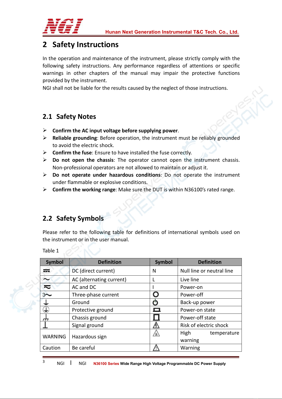
2.2 Safety Symbols
Please refer to the following table for definitions of international symbols used on
the instrument or in the user manual.
Table 1
Symbol
Definition
Symbol
Definition
DC (direct current)
N
Null line or neutral line
AC (alternating current)
L
Live line
AC and DC
I
Power-on
Three-phase current
Power-off
Ground
Back-up power
Protective ground
Power-on state
Chassis ground
Power-off state
Signal ground
Risk of electric shock
WARNING
Hazardous sign
High temperature
warning
Caution
Be careful
Warning

Hunan Next Generation Instrumental T&C Tech. Co., Ltd.
NGI lNGI N36100 Series Wide Range High Voltage Programmable DC Power Supply
4
3 Product
3.1 Brief Introduction
N36100 series is a DC power supply with ultra compact size, high performance and
high power density. The 1U height and half 19-inch width design brings comfortable
experience with space-saving in both standalone and integrated cabinet. Maximum
output power of N36100 is 900W. In view of test characteristics of different fields
such as laboratory test, system integration test and large-scale production line test,
N36100 series adopts wide range designs to meet the needs of different application
scenarios.
3.1.1 Features
1U height + half 19-inch width, wide range and high power density
Maximum output power: 900W
Remote sense
Multiple protections: OVP, OCP, OPP, OTP
CC&CV priority function
External analog programming control (optional)
Internal resistance simulation function
Modular design, convenient for system integration
Multiple communication interfaces: LAN/CAN/RS232/RS485
SEQ test function
Auto run function after startup, editable run delay time
Hunan Next Generation Instrumental T&C Tech. Co., Ltd.
NGI lNGI N36100 Series Wide Range High Voltage Programmable DC Power Supply
5
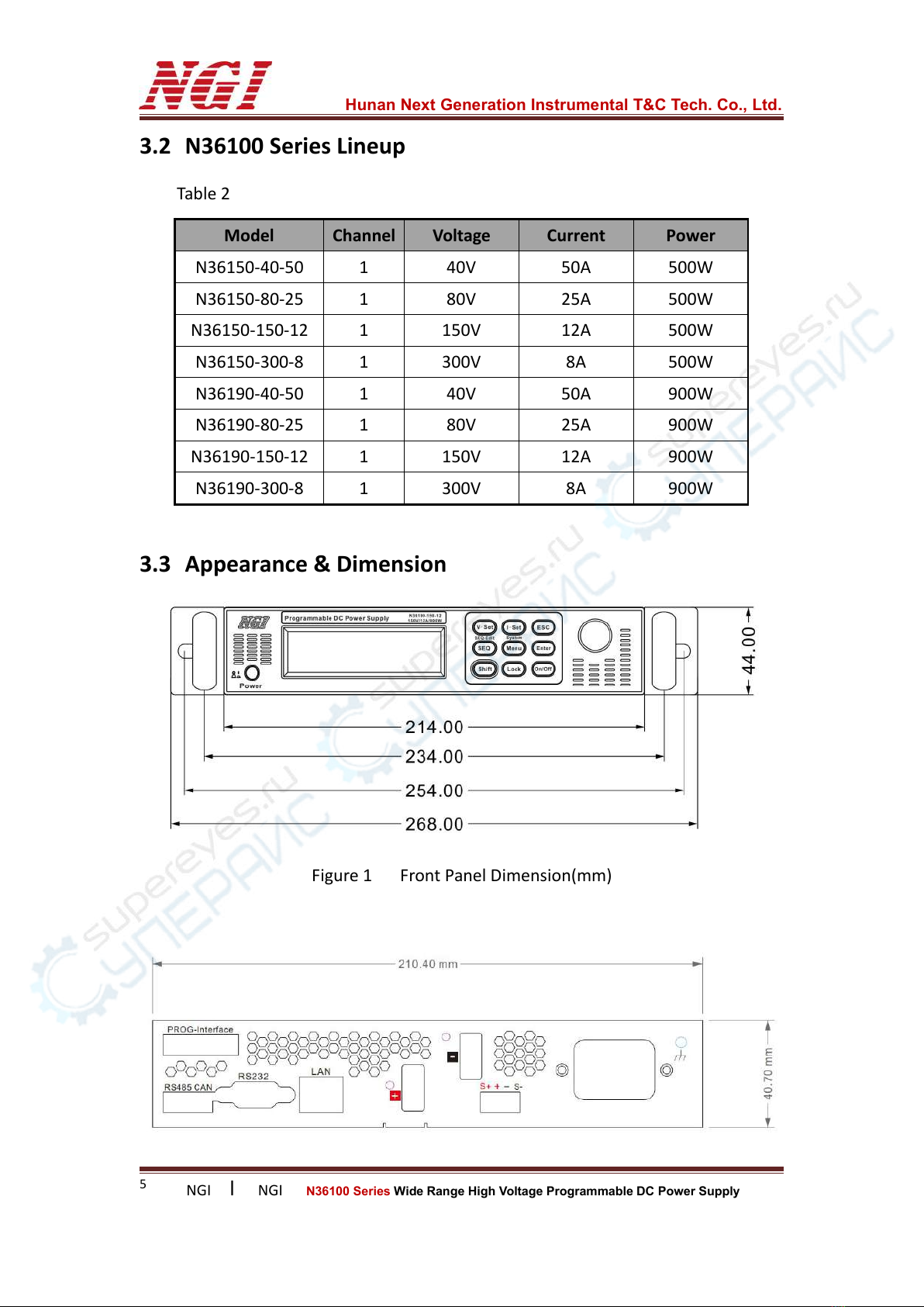
3.2 N36100 Series Lineup
Table 2
Model
Channel
Voltage
Current
Power
N36150-40-50
1
40V
50A
500W
N36150-80-25
1
80V
25A
500W
N36150-150-12
1
150V
12A
500W
N36150-300-8
1
300V
8A
500W
N36190-40-50
1
40V
50A
900W
N36190-80-25
1
80V
25A
900W
N36190-150-12
1
150V
12A
900W
N36190-300-8
1
300V
8A
900W
3.3 Appearance & Dimension
Figure 1 Front Panel Dimension(mm)
Hunan Next Generation Instrumental T&C Tech. Co., Ltd.
NGI lNGI N36100 Series Wide Range High Voltage Programmable DC Power Supply
6
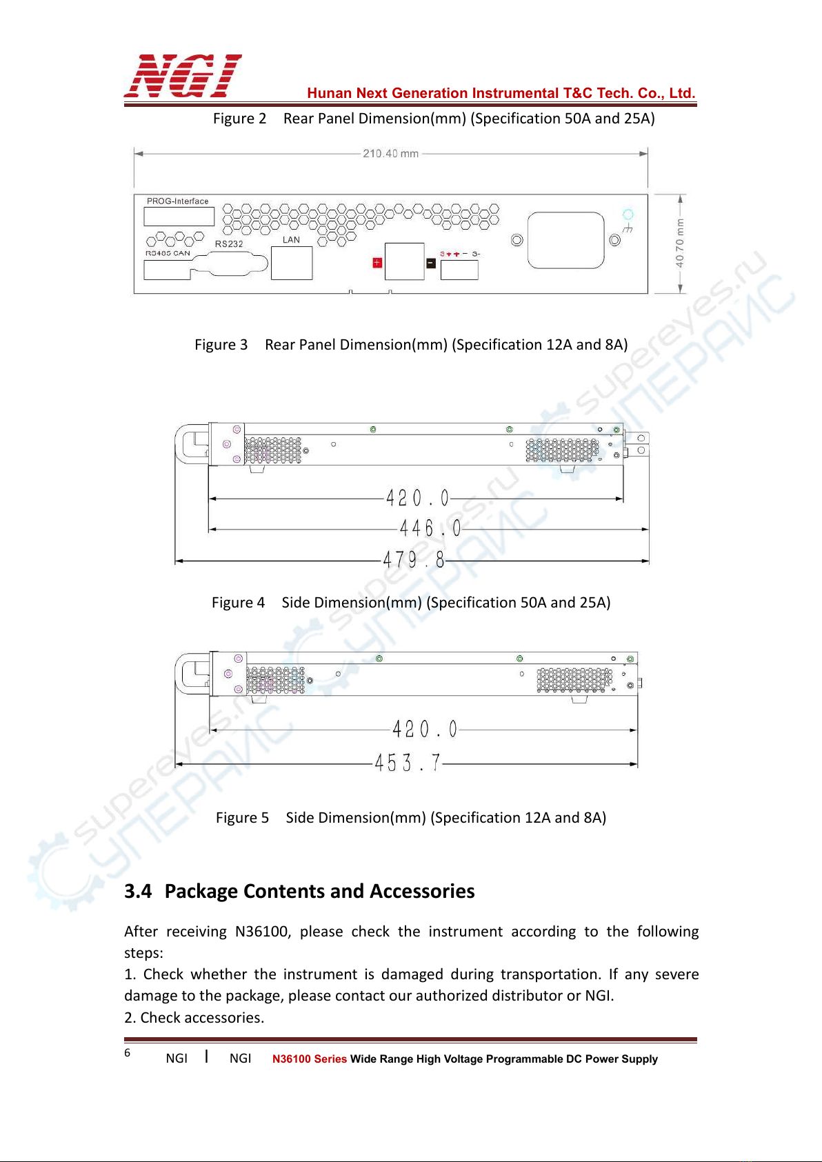
Figure 2 Rear Panel Dimension(mm) (Specification 50A and 25A)
Figure 3 Rear Panel Dimension(mm) (Specification 12A and 8A)
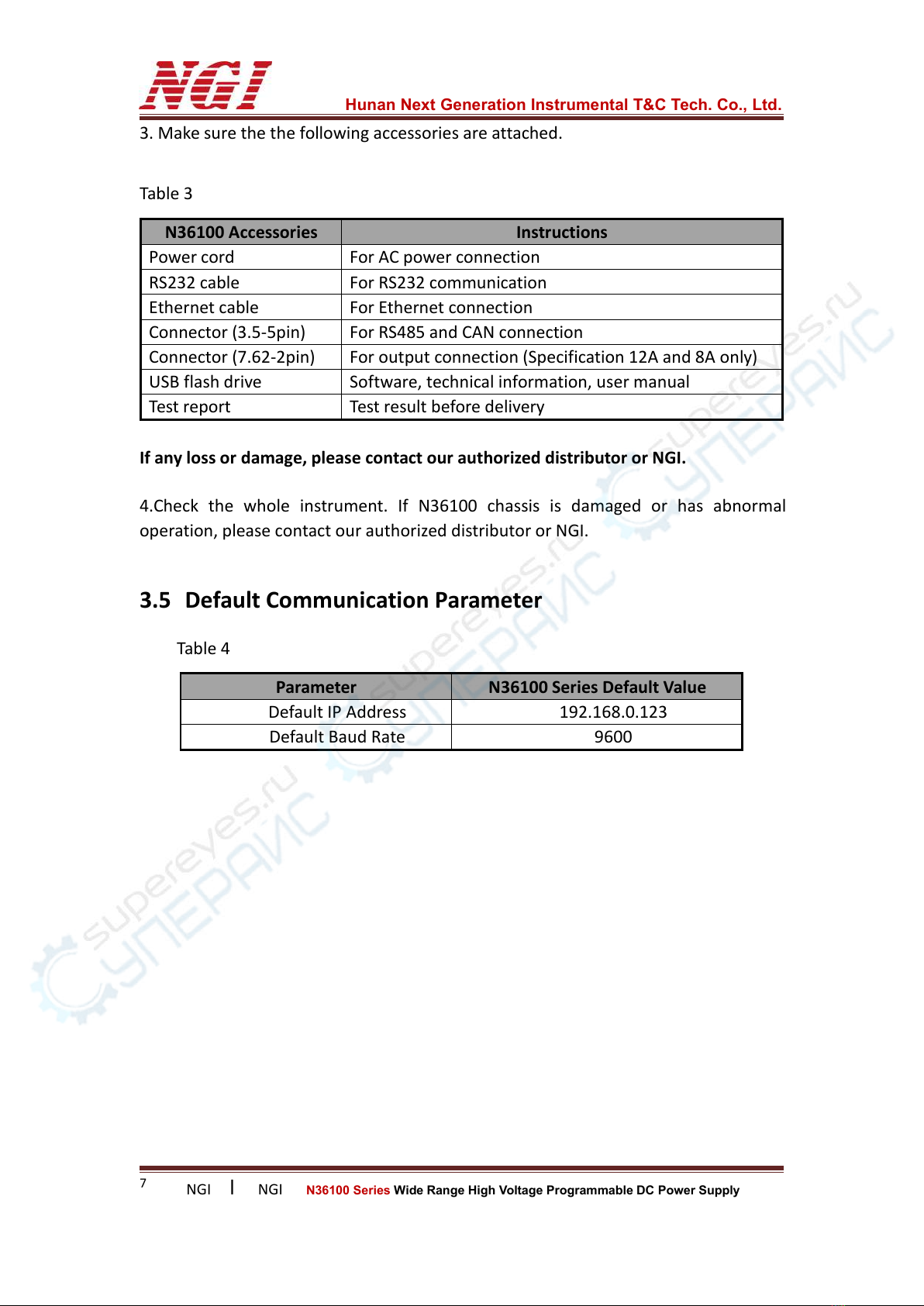
Figure 4 Side Dimension(mm) (Specification 50A and 25A)
Figure 5 Side Dimension(mm) (Specification 12A and 8A)
3.4 Package Contents and Accessories
After receiving N36100, please check the instrument according to the following
steps:
1. Check whether the instrument is damaged during transportation. If any severe
damage to the package, please contact our authorized distributor or NGI.
2. Check accessories.
Hunan Next Generation Instrumental T&C Tech. Co., Ltd.
NGI lNGI N36100 Series Wide Range High Voltage Programmable DC Power Supply
7
3. Make sure the the following accessories are attached.
Table 3
N36100 Accessories
Instructions
Power cord
For AC power connection
RS232 cable
For RS232 communication
Ethernet cable
For Ethernet connection
Connector (3.5-5pin)
For RS485 and CAN connection
Connector (7.62-2pin)
For output connection (Specification 12A and 8A only)
USB flash drive
Software, technical information, user manual
Test report
Test result before delivery
If any loss or damage, please contact our authorized distributor or NGI.
4.Check the whole instrument. If N36100 chassis is damaged or has abnormal
operation, please contact our authorized distributor or NGI.
3.5 Default Communication Parameter
Table 4
Parameter
N36100 Series Default Value
Default IP Address
192.168.0.123
Default Baud Rate
9600
Hunan Next Generation Instrumental T&C Tech. Co., Ltd.
NGI lNGI N36100 Series Wide Range High Voltage Programmable DC Power Supply
8
4 Panel Introduction
4.1 Front Panel Introduction
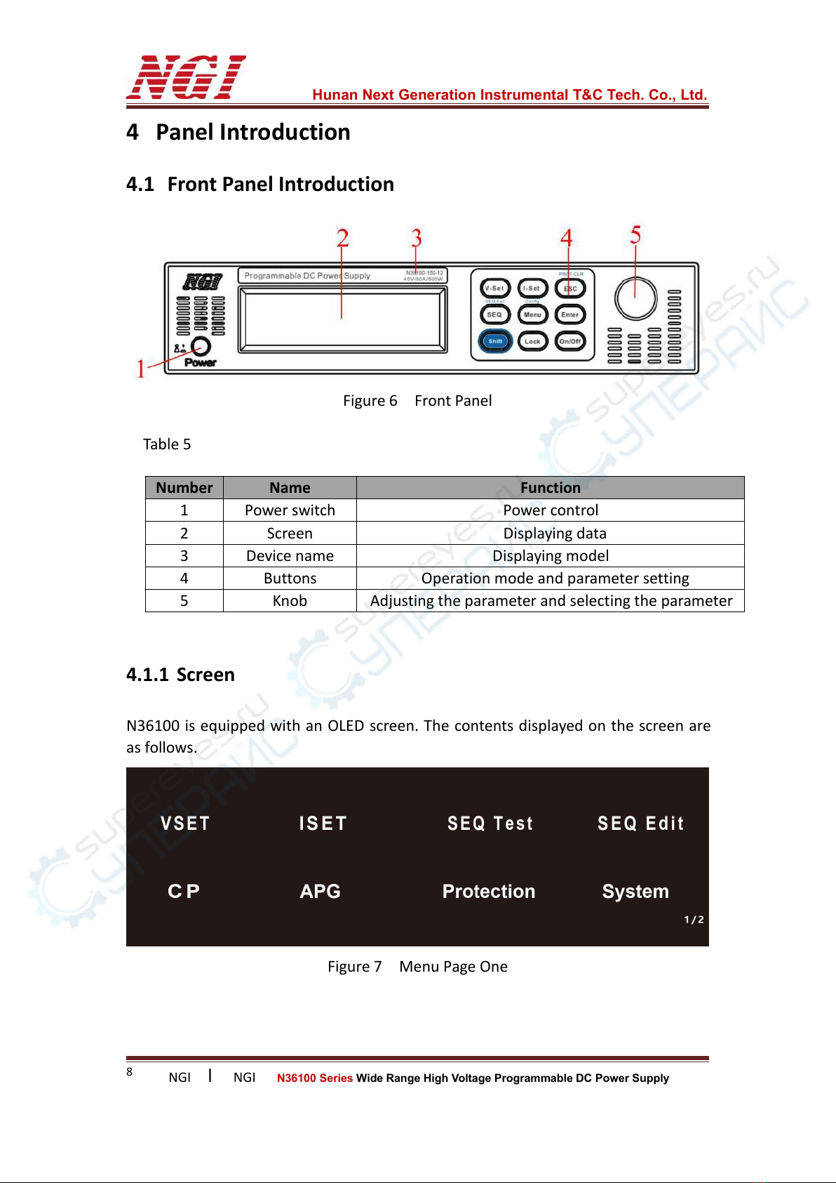
Figure 6 Front Panel
Table 5
4.1.1 Screen
N36100 is equipped with an OLED screen. The contents displayed on the screen are
as follows.
Figure 7 Menu Page One
Number
Name
Function
1
Power switch
Power control
2
Screen
Displaying data
3
Device name
Displaying model
4
Buttons
Operation mode and parameter setting
5
Knob
Adjusting the parameter and selecting the parameter
Hunan Next Generation Instrumental T&C Tech. Co., Ltd.
NGI lNGI N36100 Series Wide Range High Voltage Programmable DC Power Supply
9
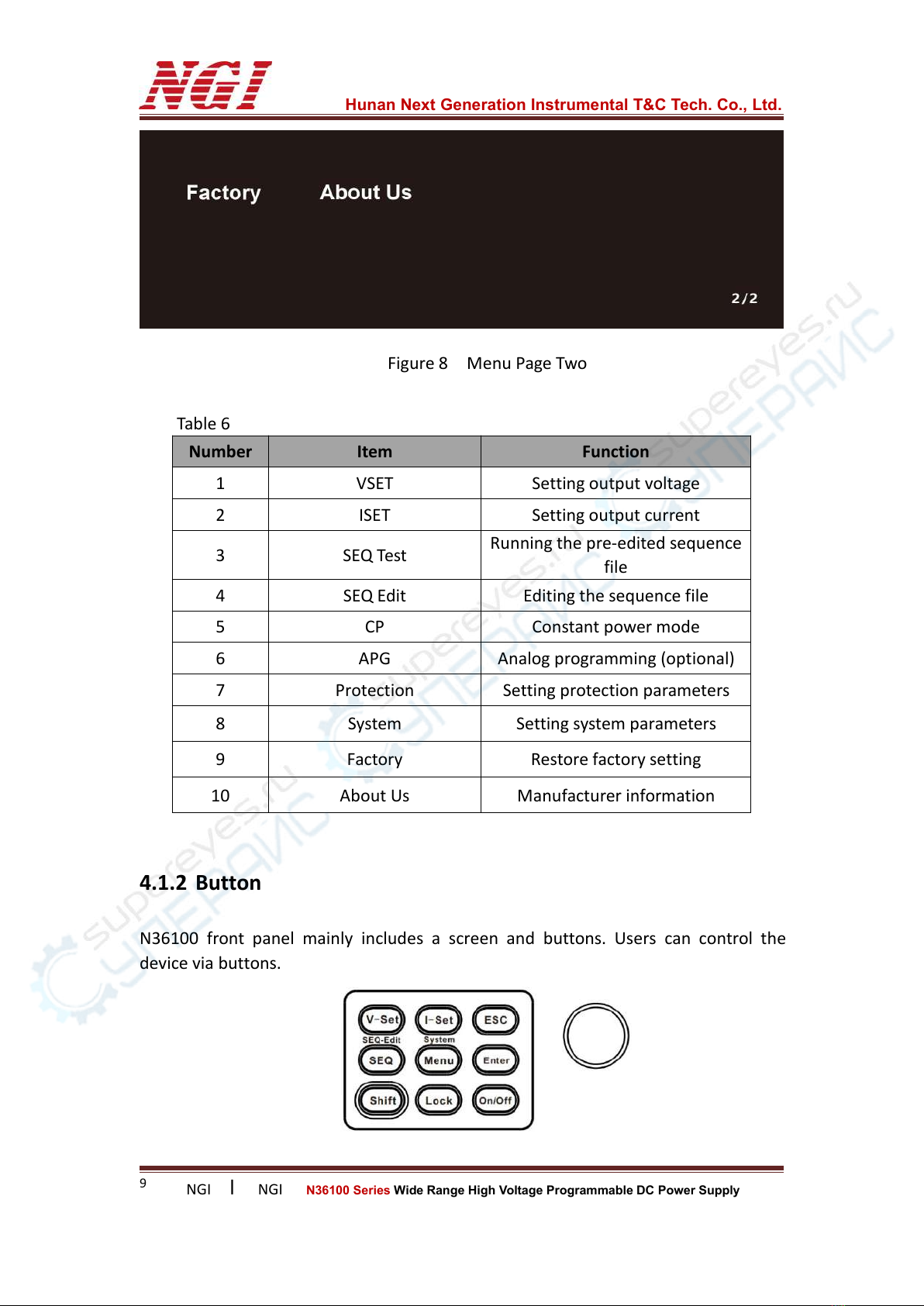
Figure 8 Menu Page Two
Table 6
Number
Item
Function
1
VSET
Setting output voltage
2
ISET
Setting output current
3
SEQ Test
Running the pre-edited sequence
file
4
SEQ Edit
Editing the sequence file
5
CP
Constant power mode
6
APG
Analog programming (optional)
7
Protection
Setting protection parameters
8
System
Setting system parameters
9
Factory
Restore factory setting
10
About Us
Manufacturer information
4.1.2 Button
N36100 front panel mainly includes a screen and buttons. Users can control the
device via buttons.

Hunan Next Generation Instrumental T&C Tech. Co., Ltd.
NGI lNGI N36100 Series Wide Range High Voltage Programmable DC Power Supply
10
Figure 9 Buttons
Table 7
Button
Function
V-Set/I-Set
To enter V/I mode
ESC
To return
Shift+ESC
To clear the protection
SEQ
To enter SEQ Test
Shift+SEQ
To enter SEQ Edit
Menu
To enter the main menu
Shift+Menu
To enter system setting
Enter
To confirm
Shift
Compound button
Lock
To lock/unlock
On/Off
To turn on/off the output
Knob
By rotating: to select the required item, adjust the parameter
By pressing: to enter the edit interface, confirm the input
4.2 Rear Panel Introduction
Figure 10 Rear Panel
Table 8
Number
Name
1
RS485 interface/CAN interface
2
RS232 interface
3
LAN port

Hunan Next Generation Instrumental T&C Tech. Co., Ltd.
NGI lNGI N36100 Series Wide Range High Voltage Programmable DC Power Supply
11
4.2.1 Output Interface
Output interface is used to connect the DUT. There are two kinds of output interfaces
for N36100 series. For current specification 50A and 25A, it adopts copper bar
interface. For specification 12A and 8A, it adopts pluggable interface.
Please select the appropriate output wire according to the specific N36100 model.
Do not use thin wires to avoid overheating, which may cause danger.
4.2.2 Four-wire Interface
Figure 11 Four-wire Interface
Table 9 Pin Definition
S+
Sense + (For remote sense)
+
Output + (For local sense, internally connected to positive output terminal )
-
Output - (For local sense, internally connected to negative output terminal )
S-
Sense - (For remote sense)
4.2.3 LAN Port
Figure 12 LAN Port
4
Output interface +
5
Output interface -
6
Four-wire interface
7
AC power socket
8
Grounding screw hole
9
Programming interface (optional)
Hunan Next Generation Instrumental T&C Tech. Co., Ltd.
NGI lNGI N36100 Series Wide Range High Voltage Programmable DC Power Supply
12
LAN port is used for remote control, by connecting N36100 with PC via an Ethernet
cable.
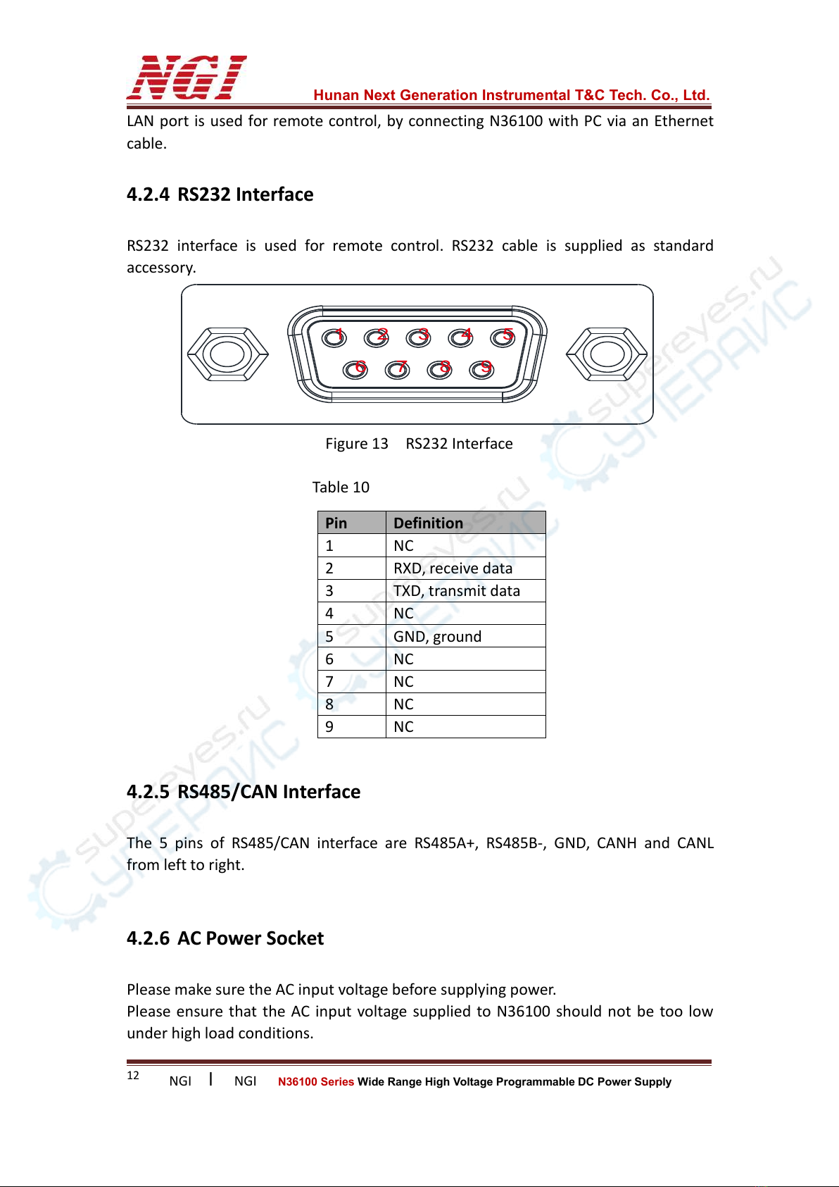
4.2.4 RS232 Interface
RS232 interface is used for remote control. RS232 cable is supplied as standard
accessory.
54321
9876
Figure 13 RS232 Interface
Table 10
4.2.5 RS485/CAN Interface
The 5 pins of RS485/CAN interface are RS485A+, RS485B-, GND, CANH and CANL
from left to right.
4.2.6 AC Power Socket
Please make sure the AC input voltage before supplying power.
Please ensure that the AC input voltage supplied to N36100 should not be too low
under high load conditions.
Pin
Definition
1
NC
2
RXD, receive data
3
TXD, transmit data
4
NC
5
GND, ground
6
NC
7
NC
8
NC
9
NC

Hunan Next Generation Instrumental T&C Tech. Co., Ltd.
NGI lNGI N36100 Series Wide Range High Voltage Programmable DC Power Supply
13
4.2.7 Grounding Screw
The chassis of N36100 is insulated from the inner live conductor. Normally, the
chassis is uncharged. If there is an accident which causes the chassis to be charged,
there is a potential difference between the chassis and the ground at this time. If it is
not well grounded and the operator accidentally touches the chassis, it will form a
closed-circuit through the human body and cause danger. Therefore, a reliable
grounding must be made between the chassis and ground to have the same potential.
In addition, a reliable grounding can also prevent the accumulation of static
electricity.
Hunan Next Generation Instrumental T&C Tech. Co., Ltd.
NGI lNGI N36100 Series Wide Range High Voltage Programmable DC Power Supply
14
Warning: Please confirm the AC input power and connect to correct AC power. Wrong
AC power may cause serious damage to the instrument.
5 Power-on Test
Power-on test includes two parts: power-on inspection and output inspection.
This test is to ensure N36100 can be started and used properly.
5.1 Power-on Inspection
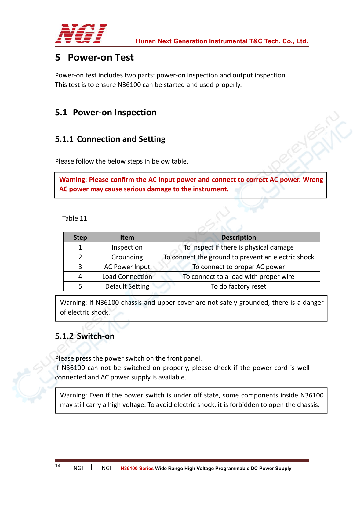
5.1.1 Connection and Setting
Please follow the below steps in below table.
Table 11
5.1.2 Switch-on
Please press the power switch on the front panel.
If N36100 can not be switched on properly, please check if the power cord is well
connected and AC power supply is available.
Step
Item
Description
1
Inspection
To inspect if there is physical damage
2
Grounding
To connect the ground to prevent an electric shock
3
AC Power Input
To connect to proper AC power
4
Load Connection
To connect to a load with proper wire
5
Default Setting
To do factory reset
Warning: If N36100 chassis and upper cover are not safely grounded, there is a danger
of electric shock.
Warning: Even if the power switch is under off state, some components inside N36100
may still carry a high voltage. To avoid electric shock, it is forbidden to open the chassis.

Hunan Next Generation Instrumental T&C Tech. Co., Ltd.
NGI lNGI N36100 Series Wide Range High Voltage Programmable DC Power Supply
15
5.2 Output Inspection
The output inspection can ensure that N36100 can reach its rated output and can
perform the operations on the front panel properly.
5.2.1 Output Voltage Inspection
Steps to verify N36100’s basic voltage function without connecting to a load:
1. Press the power switch.
2. Set voltage to 1V.
3. Press On/Off button to output.
4. Check if the readback voltage is close to 1V.
5. Check if the voltage can be set from 0V to full range.
5.2.2 Output Current Inspection
Steps to verify N36100’s basic function during output short-circuit:
1. Press the power switch.
2. Make sure the output is OFF.
3. Connect an insulated wire to short circuit the positive and negative electrodes
at the output of N36100. The wire used should be able to bear the maximum output
current of N36100.
4. Set current to 1A.
5. Press On/Off button to output.
6. Check if the readback current is close to 1A.
7. Check if the current can be set from 0A to full range.

Hunan Next Generation Instrumental T&C Tech. Co., Ltd.
NGI lNGI N36100 Series Wide Range High Voltage Programmable DC Power Supply
16
Note: Please refer to the recommended wire gauge selection table in the appendix.
6 Load Connection
6.1 Load Wire
Load wire is not included among N36100 series standard accessories. Users need to
prepare load wire. Please refer to the follow requirements while selecting load wire.
1. The maximum allowable current of wire.
2. The insulation level of wire should not be lower than the maximum output
voltage of the power supply.
3. The maximum wire length and voltage drop.
4. Noise and impedance effects on the load wire.
6.2 Maximum Allowable Current
The following two factors should be considered when selecting the wire gauge.
1. The wire should be thick enough to avoid overheating when carrying rated load
current or load short-circuit current. The greater shall prevail.
2. The wire gauge should be selected properly to minimize the voltage drop on each
wire and to prevent excessive output power consumption of the power supply, which
affects the load regulation. Although N36100 series adopts remote sense to
compensate the voltage, it is still recommended to minimize the voltage drop.
6.3 Effect of Noise and Impedance
In order to reduce noise or radiation, the load wire and the remote sense wire should
be twisted pair. The wire length should be as short as possible. Shielded wires must
be used in high noise environments. The shielding part is connected to chassis
through the grounding screw hole on rear panel.
Note: Please refer to the recommended wire gauge selection table in the appendix.
Warning: Please turn off the AC input power before changing any connections on the
rear panel. Before supplying power, please check and confirm that all connections are
fastened. Touching any terminal or interface on the rear panel with N36100 powered on
may cause electric shock.

Hunan Next Generation Instrumental T&C Tech. Co., Ltd.
NGI lNGI N36100 Series Wide Range High Voltage Programmable DC Power Supply
17
Even if the noise is not loud, the load wire and remote sense wire should also be
twisted pair to reduce coupling and increase the stability of power supply. The
remote sense wire must be separated from AC input power cord.
Twisted-pair load wire can reduce the parasitic inductance of the wire and prevent
high-frequency voltage peak on the load and the output of power supply, caused by
fluctuation of the load current.
The impedance between the output of power supply and the load makes the ripple &
noise on the load higher than at the rear panel terminal of power supply. If necessary,
an additional filter circuit with a bypass capacitor can be connected to the load to
limit the high-frequency load current.
6.4 Inductive Load
When using N36100 to supply power to inductive loads such as motors, users can
connect a diode across the output of N36100 since the inductive load will produce a
voltage spike which is harmful to N36100. The rated voltage and current of the diode
should be higher than the rated output voltage and current of power supply. The
negative polarity of diode is connected to the positive output of N36100. The
positive polarity is connected to the negative output of N36100.
When using N36100 to supply power to inductive loads such as motors, load
transients, such as counter electromotive force from motors, may occur. Please
connect a surge current suppressor across the output of N36100 to protect N36100.
The rated breakdown voltage of surge current suppressor must be approximately
10% higher than the rated output voltage of N36100.
6.5 Local Sense and Remote Sense
The four-wire interface at rear panel is used for local sense and remote sense. Please
refer to four-wire interface introduction. N36100 is supplied with 4-pin green
connector for remote sense at the rear panel.

Hunan Next Generation Instrumental T&C Tech. Co., Ltd.
NGI lNGI N36100 Series Wide Range High Voltage Programmable DC Power Supply
18
Figure 14 4-pin Green Connector
6.5.1 Local Sense
In local sense, output voltage is adjusted at the output terminal of N36100. This way
does not compensate for the voltage drop on the load wire. It is recommended to
use local sense when the load current is low or the load regulation is not very critical.
6.5.2 Remote Sense
Due to the parasitic resistance on the wire, a voltage drop will be generated on the
wire after the current flows. Assuming that output of the power supply is set to
55V/10A and the resistance of the load wire is 0.5 ohms, a 5V voltage drop will be
generated on the wire. The actual voltage reaching the load is only 50V, which affects
the output accuracy of the power supply. In this case, it is necessary to compensate
for the voltage drop on the wire.
The remote sense wire is directly connected to the load from four-wire interface on
the rear panel of power supply. Since the remote sense wire is directly connected to
the high impedance measurement circuit inside the supply, and the current on
remote sense wire is very low, the voltage drop generated is negligible. The voltage
across the load is fed back to the power supply control loop via remote sense wire.
The supply will adjust its output to compensate for the voltage drop on the load wire
so that the voltage across the load is equal to the set voltage.
It is recommended to use remote sense when load regulation is very critical. The
procedure is as below.
1. Press the power switch to shut off the power supply.
2. Disconnect the jumpers on the 4-pin green connector.
3. Connect S+ to positive polarity on load and S- to negative polarity on load with
proper wire.
4. Plug the connector into the four-wire interface on rear panel of supply.
5. Connect the output of power supply to the load.
6. Press the power switch to power on the power supply.
Note: On the 4-pin connector, jumpers have been used to connect S+ to +and S- to -.
When using local sense, please put the 4-pin connector at rear panel. Unplugging the
connector will leave the remote sense terminal disconnected, which will affect the
voltage regulation and may cause the power supply to be unstable and dangerous.
This manual suits for next models
8
Table of contents
Other NGI Power Supply manuals


Popular Power Supply manuals by other brands


Antec
Antec Mini P180 White user manual

National Instruments
National Instruments FieldPoint FP-PS-4 operating instructions

YOSHINO
YOSHINO B330 SST quick start guide

StarTech.com
StarTech.com ATXPOW350DF Instruction guide

Rolls
Rolls RPB486 quick start guide

Delta Electronics
Delta Electronics Q48SB Specifications


