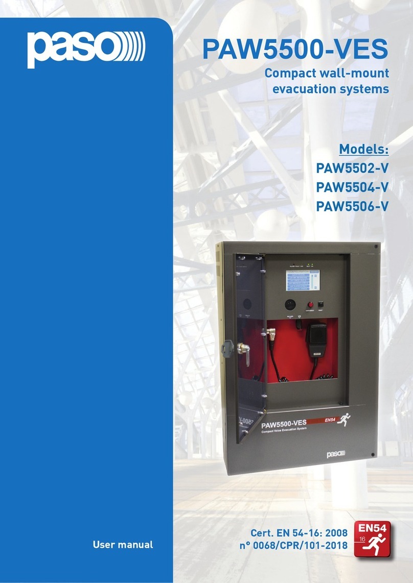
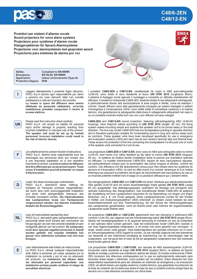
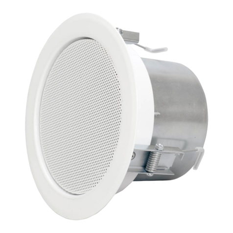
Paso PAW5500-VES Series User manual

SISTEMI COMPATTI ALL-IN-ONE
ALL-IN-ONE COMPACT SYSTEMS
• PAW5502-V
• PAW5504-V
• PAW5506-V
PAW5500-VES
Nel ringraziarVi per aver scelto un prodotto PASO, vogliamo ricordarVi
che la nostra azienda opera con sistema di qualità certicato. Tutti
i nostri prodotti vengono pertanto controllati in ogni fase della
produzione per garantirVi la piena soddisfazione del Vostro acquisto.
Per ogni evenienza la garanzia coprirà, nel periodo di validità, eventuali
difetti di fabbricazione. Vi raccomandiamo di leggere attentamente le
istruzioni d’uso per sfruttare appieno le prestazioni oerte da questo
prodotto e per evitare eventuali problemi.
La gamma PAW5500-VES comprende tre sistemi di evacuazione
vocale integrati per impianti d’emergenza, appositamente studiati
per il montaggio a parete e dotati di un’unità di controllo certicato
conforme a norme EN 54-16:2008 e EN 54-4. Questi sistemi sono in
grado di gestire, a seconda del modello, da 2 a 6 zone d’allarme –
ognuna delle quali pilotata da un singolo amplicatore - postazioni
microfoniche a distanza ed ingressi controllati da connettere ad una
centrale antincendio. È possibile collegare fra loro no ad un massimo
di 6 sistemi (per un totale massimo di 36 zone gestite).
The new PAW5500-VES range incudes three integrated voice evacuation
systems for emergency facilities, designed specically for wall-mounting
and equipped with control units, certied in compliance with EN 54-
16:2008 / EN 54-4 standards. Depending on the model, these systems
are capable of managing from 2 to 6 alarm zones, each driven by a
single amplier, as well as remote microphone stations and controlled
inputs to be connected to a central re-ghting system.
It is possible to connect up to a maximum of 6 of these systems to one
other (for managing an overall maximum of 36 zones).
While thanking you for having chosen a PASO product, we
would like to
remind you that our company works according to a certied Quality
System.This means that all our products are checked during every phase
of manufacturing in order to ensure that you will be fully satised with
your purchase. In any case, the guarantee will cover any manufacturing
aws during the guarantee period. We recommend that you read the
instructions for use and follow them carefully in order to exploit in full
the performance of this product and use it correctly.
Cert. EN 54-16: 2008
n° 0068/CPR/101-2018
MONTAGGIO A PARETE
WALL-MOUNTING
1. AVVERTENZE 1. WARNINGS
2. DESCRIZIONEGENERALE 2. GENERALDESCRIPTION
1.1 ALIMENTAZIONE E MESSA A TERRA
Questi apparecchi sono predisposti per il funzionamento con tensione
di rete a 230 Vca +10% / -15% 50/60 Hz ed alimentazione in corrente
continua a 24Vcc erogata dalle batterie interne.
1.1 POWER SUPPLY AND EARTHING
These items of equipment are intended to work on a 230 VAC +10% /
-15%, 50/60 Hz mains voltage and a 24 VDC supply from the internal
batteries.
1.2 NOTE DI SICUREZZA
!IMPORTANTE – CARATTERISTICHE DELL’IMPIANTO ELETTRICO
L’alimentazione in corrente alternata proveniente da rete elettrica
DEVE essere soggetta ad un interruttore magnetotermico bipolare
differenziale con corrente di 10-16A dedicato ESCLUSIVAMENTE
all’apparecchio.
!IMPORTANTE
Questi apparecchi sono stati progettati per essere connessi ad una rete
d’alimentazione compresa di terra.
Assicurarsi che gli apparecchi siano sempre connessi ad un impianto
di terra a norma di legge.
SI RIMANDA ALLA SEZIONE ‘INSTALLAZIONE E CONNESSIONI’ DEL
MANUALEPERLERELATIVEPROCEDURE,RISERVATEESCLUSIVAMENTE
A PERSONALE SPECIALIZZATO E ADDESTRATO.
1.2 SAFETY NOTES
!N.B. - FEATURES OF THE WIRING SYSTEM
The mains AC power MUST be supplied through a two-pole dierential
thermal-magnetic circuit breaker with a current of 10 to 16A dedicated
SOLELY to the equipment.
!N.B.
These devices have been designed to be connected to an earthed
power supply.
Make sure that the equipment is always connected to earth in
accordance with legal regulations.
REFER TO THE ‘INSTALLATION AND CONNECTIONS’ SECTION FOR
THE RELEVANT PROCEDURES, TO BE CARRIED OUT BY TRAINED
SPECIALISED PERSONNEL ONLY.

2
PAW5502-V, PAW5504-V, PAW5506-V
RIFERIMENTI NUMERATI
Porta frontale
1. Display 4.3” retroilluminato con touchscreen.
2. Altoparlante integrato.
3. Microfono palmare VVF.
4. Pulsante RESET.
5. Pulsante EMERGENCY.
6. Led di stato.
7. Vano per scheda SD.
8. Presa USB per dispositivo esterno.
Circuiti interni
9. n°7 contatti d’ingresso controllati.
10. n°3 contatti d’uscita a relè.
11. Ingresso RJ45 per postazioni microfoniche d’emergenza.
12. Ingresso RJ45 per postazioni microfoniche broadcast.
13. Ingressi/uscite RJ45 per collegamento ad altri PAW5500-VES.
14. Morsettiera ingresso per sorgenti ausiliarie con precedenza.
15. Morsettiera ingresso per sorgenti musicali.
16. Collegamento batterie 24Vcc.
17. Collegamento alimentazione 230 Vac.
20. Morsettiera collegamento 21÷29V.
Morsettiera connessioni
18. Collegamento amplicatore di riserva.
19. Collegamento diusori zone.
NUMBERED REFERENCES
Front door
1. Backlit 4.3” display w/touchscreen.
2. Integrated loudspeaker.
3. Handheld reman’s microphone.
4. RESET button.
5. EMERGENCY button.
6. Status LEDs.
7. SD card slot.
8. USB socket for external device.
Internal circuits
9. 7 o controlled input contacts.
10. 3 o relay output contacts.
11. RJ45 input for emergency microphone stations.
12. RJ45 input for paging microphone stations.
13. RJ45 inputs/outputs towards other PAW5500-VES.
14. Input for auxiliary sources with precedence contact.
15. Input for music sources.
16. Connection to 24VDC batteries.
17. Connection to 230 VAC PS.
20.
Terminal strip for 21 to 29 V connection.
Terminal strip
18. Connection of standby amplier.
19. Connection of loudspeakers lines.

3
PAW5502-V, PAW5504-V, PAW5506-V
!IMPORTANTE
Si ricorda che le operazioni riportate in questa sezione del manuale
devono essere eseguite ESCLUSIVAMENTE da personale specializzato,
addestrato e qualificato all’installazione ed alla manutenzione
dell’apparecchio: l’apertura del PAW rende accessibili parti ad alto
rischio di scosse elettriche.
È consigliato prevedere l’installazione dell’apparecchio in un ambiente
chiuso e riparato, che non sia a contatto con possibili fonti di
danneggiamento (pioggia, umidità, alte temperature ecc.). L’inserimento
dei cavi può essere attuato eliminando a seconda delle esigenze i tappi
chiudifori superiori o la portella posteriore (in entrambi i casi, utilizzare
un cacciavite piatto o una tronchese per sollevarli e rimuoverli).
!Si raccomanda di tenere separati i cavi di alimentazione da quelli
dedicati alle altre connessioni.
!N:B.
Please remind that the operations illustrated in this part of the
manual must be carried out by specialised personnel ONLY, trained
and qualied in the equipment installation and maintenance. When
the PAW is opened, parts entailing a high risk of electric shocks
become accessible.
It is advisable to install the equipment in a closed and sheltered place,
protected against possible sources of damage (rain, moisture, high
temperatures, etc.). Depending on requirements, the cables can be
inserted by eliminating either the plugs sealing the holes in the top
or the rear door (in both cases use a at screwdriver or a cutter to lift
them and remove them).
!It is important to keep the power cables separate from those
dedicated to the other connections.
3. INSTALLAZIONEECONNESSIONI 3. INSTALLATIONANDCONNECTIONS
3.1 INSTALLAZIONE A PARETE
Posizionare la dima di cartone contenuta nella confezione ad un’altezza
consona che la renda accessibile all’utente: il display frontale dovrebbe
infatti essere idealmente ad altezza occhio. Segnare sulla parete i cinque
punti e, dopo aver praticato i fori, inserirvi dei tasselli Fisher (Ø minimo
= 9 mm) dotati di bulloni. Utilizzando i tasselli come spine di riferimento,
sollevare l’apparecchio ed agganciarlo alla parete. Si consiglia che
l’operazione venga eseguita da almeno due persone. Serrare i bulloni.
3.1 WALL MOUNTING
Take the cardboard template included in the package and position it
at a suitable height so that it is accessible to the user. Ideally, the front
display should be at eye level. Having decided on the position, mark the
ve points on the wall and t Fischer wall plugs (min. Ø 9 mm) equipped
with bolts into them. Using the wall plugs as reference pins, lift the
equipment and hook it to the wall. It is advisable for this activity to be
carried out by two people. Tighten the bolts.

4
PAW5502-V, PAW5504-V, PAW5506-V
3.2 COLLEGAMENTI
!IMPORTANTE
Vericare che l’interruttore magnetotermico a monte sia SPENTO.
Se così non fosse, provvedere a portarlo in posizione OFF prima di
eseguire qualsiasi altra operazione all’interno dell’armadio: pericolo
di scossa elettrica.
!IMPORTANTE
È fondamentale seguire la corretta sequenza di alimentazione
dell’apparecchio, pena il danneggiamento dello stesso.
!N.B.:
It is essential to follow the correct sequence for powering up the
equipment, failing which it could be damaged.
A) COLLEGAMENTO POSTAZIONI D’EMERGENZA (Circuito CPU)
Utilizzare un cavo CAT.5e SF/UTP per collegare la presa EMERG. (11)
alle prese‘IN/OUT’ delle postazioni remote d’emergenza Serie PMB132
(max 4) o in alternativa TSB8500-V (max 2).
A) CONNECTION OF EMERGENCY UNITS (CPU circuit)
Use a CAT. 5e SF/UTP cable for connecting the EMERG. socket (11) to
the ‘IN/OUT’ sockets of the PMB132 remote emergency units (up to 4).
As an alternative, it is possible to connect up to 2 touch screen units
TSB8500-V.
B) COLLEGAMENTO POSTAZIONI BROADCAST Circuito CPU)
Utilizzare un cavo CAT.5e SF/UTP per collegare la presa BROAD. (12)
alle prese‘IN/OUT’ delle postazioni broadcast Serie PMB106/112.
B) CONNECTION OF PAGING UNITS (CPU circuit)
Use a CAT. 5e SF/UTP cable for connecting the BROAD. socket (12) to
the‘IN/OUT’sockets of the PMB106/112 paging units.
C) COLLEGAMENTO VERSO ALTRI PAW5500-VES (Circuito CPU)
Utilizzare cavi CAT.5e SF/UTP per collegare tramite le prese REMOTE
LINK A/B (13) altri sistemi compatti PAW5500-VES (no a un massimo
di 6 sistemi in totale).
C) CONNECTION to other PAW5500-VES units (CPU circuit)
Use CAT. 5e SF/UTP cables for connecting other PAW5500-VES units (up
to a maximum total of 6 per system) via the REMOTE LINK A/B sockets
(13).
3.2 CONNECTIONS
!N.B.:
Check that the main thermal-magnetic circuit breaker is switched OFF.
If it is not, switch it OFF before carrying out any other activities in the
cabinet as there is a danger of electric shocks.
87654321
Pin 8
Pin 1
12345678
Pin 1
Pin 8
Pin Descrizione
1Audio +
2Audio –
3GND
4Non connesso
5Non connesso
6+ Vcc
7Seriale +
8Seriale –
Shield GND
RJ45 IN
A
B
C
D) COLLEGAMENTO INGRESSO AUSILIARIO (Circuito CPU)
I morsetti AUX (14) sono disponibili per la connessione di sorgenti ausiliarie (ad es. un
centralino telefonico od una base per annunci con contatto pulito di precedenza). Nel
primo caso, deve essere inserito un jumper nel connettore CN9 in posizione“P–”; nel
secondo caso, il jumper deve essere inserito in posizione“P+”.
D) CONNECTION OF AUXILIARY INPUT (CPU circuit)
The AUX terminals (12) are available for connecting auxiliary sources (e.g. a PABX or a
base for announcements with a free voltage precedence contact). In the rst case, to
which Fig. 1 refers, it is necessary to t a jumper onto connector CN9 in position“P-”.
In the second case, t the jumper in position“P+”.
D

5
PAW5502-V, PAW5504-V, PAW5506-V
E) COLLEGAMENTO INGRESSO MUSICA (Circuito CPU)
I morsetti MUSIC (15) sono disponibili per la connessione di sorgenti musicali bilancia-
te esterne (lettore CD, tuner etc.).
E) CONNECTION OF MUSIC INPUT (CPU circuit)
The MUSIC terminals (15) are available for connecting outside balanced music sources
(CD player, tuner etc.).
F) COLLEGAMENTO CONTATTI D’INGRESSO (Circuito CPU)
Alla morsettiera CONTACT (9) sono disponibili 7 contatti d’ingresso: in gura un esempio
di collegamento dei contatti 1 (tipo sorvegliato) e 2 (tipo non sorvegliato).
F) CONNECTION OF INPUT CONTACTS (CPU circuit)
The CONTACT terminal strip (9) provides 7 input contacts. An example of a connection
of contact 1 (controlled type) and 2 (not controlled type) is shown in the gure.
G) COLLEGAMENTO USCITE RELÈ (Circuito CPU)
Ai morsetti R1, R2 e R3 (10) sono disponibili 3 uscite a relè per segnalazione verso
periferiche esterne.
G) CONNECTION OF RELAY OUTPUTS (CPU circuit)
Three relay outputs are available on terminals R1, R2 and R3 (10) for signalling towards
outside peripheral units.
H) COLLEGAMENTO 21÷29V (Circuito CPU)
Ai morsetti 24 V (20), a seconda delle modalità di funzionamento del PAW, è possibile
prelevare un’alimentazione compresa tra i 21 e i 29 V, con un assorbimento massimo di
50 mA.
H) 21 TO 29V CONNECTION (CPU circuit)
Depending on how the PAW will be working, it is possible to receive a 21 to 24V power
supply on the 24V terminals (20), with a maximum absorption of 50 mA.
I) COLLEGAMENTO LINEE ALTOPARLANTI (morsettiera)
I morsetti A/B (19) sono dedicati alla connessione delle linee altorparlanti. Nella gura
che segue viene illustrato il collegamento di un modello PAW5502-V (2 zone).
I) CONNECTION OF LOUDSPEAKER LINES (terminal strip)
Terminals A/B (19) are dedicated terminals for connection of the loudspeaker lines.
The wiring of a PAW5502-V model (2 zones) is shown in the gure below.
J) COLLEGAMENTO AMPLIFICATORE DI RISERVA (morsettiera)
È possibile utilizzare l’ultimo amplicatore come riserva, ponticellando i morsetti R(18)
con i suoi morsetti d’uscita A/B (19). La gura illustra il collegamento di un modello
PAW5502-V (si ottiene così sistema a singola zona con amplicatore di riserva).
J) CONNECTION OF THE STANDBY AMPLIFIER (terminal strip)
Using both terminal strip R (18) and A/B (19) it is possible to set a standby amplifer:
here’s the connection of a PAW5502-V model (1 zone + standby amplier).
E
F
G
I
H
J

6
PAW5502-V, PAW5504-V, PAW5506-V
K) / L) COLLEGAMENTO ALIMENTAZIONI
! IMPORTANTE :Vericare che l’interruttore magnetotermico a monte sia
SPENTO. Se così non fosse, provvedere a portarlo in posizione OFF prima
di eseguire qualsiasi altra operazione all’interno dell’armadio: pericolo
di scossa elettrica. Questi apparecchi sono stati progettati per essere
connessi ad una rete d’alimentazione compresa di terra. Assicurarsi che
gli apparecchi siano sempre connessi ad un impianto di terra a norma
di legge. È di fondamentale importanza seguire la corretta sequenza di
alimentazione dell’apparecchio, pena il danneggiamento dell’oggetto.
1> Vericare che l’interruttore magnetotermico a monte sia spento.
2> Collegare il cavo di alimentazione proveniente dall’interruttore
magnetotermico e il cavo di terra ai contatti della morsettiera (A).
3> Collegare i terminali capicorda esterni (B) delle batterie rispettando le
polarità.
4> Portare in posizione ON l’interruttore magnetotermico.
5> Ponticellare fra loro i terminali interni delle batterie utilizzando il cavo
(C) in dotazione.
6> Chiudere la porta frontale serrando a fondo le viti.
---
1> Check that the main thermal-magnetic circuit breaker is switched OFF.
2> Connect the power cable coming from the thermal-magnetic circuit
breaker and the earth cable to the contacts on the terminal strip (A) -
see gure.
3> Connect the external terminals (B) of the batteries,
observing the correct polarities.
4> Switch the thermal-magnetic circuit breaker ON.
5> Make a jumper between the inside terminals of the batteries using the
cable (C) included in the supply.
6> Close the front door, tightening the screws rmly.
K) / L) CONNECTION OF POWER SUPPLIES
! N.B.: Check that the main thermal-magnetic circuit breaker is
switched OFF. If it is not, switch it OFF before carrying out any
other activities in the cabinet as there is a danger of electric
shocks. These devices have been designed to be connected
to an earthed power supply. Make sure that the equipment is
always connected toearth in accordance with legalregulations.
It is essential to follow the correct sequence for powering up
the equipment, failing which it could be damaged.
Da questo momento in avanti il PAW è in funzione.
NOTA: in caso di apertura della porta frontale, gli amplicatori vengono
disattivati in automatico e possono essere riattivati solo da personale
specializzato tramite una apposita voce di menu.
From now on the PAW is working.
NOTE: If the front door is opened, the ampliers are deactivated automatically,
and can be re-activated by specialised personnel only by using a specic
menu item.

7
PAW5502-V, PAW5504-V, PAW5506-V
4. OPERATIVITÀ E NOMENCLATURA
Di seguito un elenco delle modalità di segnalazione delle condizioni
operative del sistema e di denizioni utilizzate nei successivi paragra
del manuale, completate da indicazioni di carattere generale.
4. OPERATIONAL CONDITIONS AND TERMINOLOGY
Following is a list of how the operating conditions of the system are
signalled and of the denitions used on the subsequent pages of the
manual, completed by indications of a general nature.
4.1 SEGNALAZIONE DELLE CONDIZIONI OPERATIVE
ll PAW è strutturato per segnalare le dierenti condizioni operative come
da seguenti denizioni:
Stato di Quiete (Led ALARM – FAULT – SYS spenti)
Condizione operativa normale, senza guasti o emergenze in corso.
Stato di Allarme (Led ALARM acceso)
Condizione operativa che segnala la presenza di almeno un segnale
d’allarme – preregistrato o a viva voce - in corso su almeno una zona
d’uscita.
Stato di Guasto (Led FAULT acceso)
Condizione operativa che segnala la presenza di almeno un guasto in
corso, rilevato dal sistema di diagnosi interna con l’accensione del led
relativo.
Guasto di Sistema (Led SYS acceso)
Condizione operativa che segnala il blocco del sistema causato da un
malfunzionamento temporaneo o permanente della CPU, rilevato dal
watchdog di supervisione.
Emergenza Automatica
(Display ‘AUTOMATIC EMERGENCY’ con zone attive)
Sequenza di operazioni richiamate da periferica esterna, collegata agli
ingressi di controllo che, in base alla programmazione degli stessi, attiva
la condizione di ‘Stato di Allarme’ o il Reset degli allarmi.
Emergenza Manuale
(Led del pulsante EMERGENCY acceso/lampeggiante)
Procedura di intervento sui controlli manuali del sistema, da parte di
operatore autorizzato, per l’attivazione di sorgenti d’emergenza. Le
operazioni svolte in Emergenza Manuale hanno priorità superiore a
quelle attivate dall’Emergenza Automatica.
4.1 SIGNALLING OF OPERATING CONDITIONS
The PAW is designed to signal the dierent operating conditions as
dened below:
Idle state (ALARM, FAULT and SYS LEDs o)
Normal operating condition, with no current faults or emergencies.
Alarm Status (ALARM LED on)
Operating condition signalling the presence of at least one alarm
signal, either pre-recorded or live, in at least one output zone.
Faulty status (FAULT LED on)
Operating condition signalling the presence of at least one fault detected
by the internal diagnostic system, with the relevant LED turning on.
System failure (SYS LED on)
Operating condition signalling that the system has crashed due to
temporary or permanent CPU malfunctioning, detected by the watch-
dog device.
Automatic Emergency
(Display showing ‘AUTOMATIC EMERGENCY’ with active zones)
Sequence of operations recalled by anexternal peripheral unitconnected
to the control inputs that, depending on how these are programmed,
activates the Alarm Status or resets the alarms.
Manual Emergency
(LED of the EMERGENCY button steady ON or ashing)
Procedure of action on the system manual controls by an authorised
operator, in order to activate emergency sources. Operations in the
Manual Emergency mode have priority over those activated in the
Automatic Emergency mode.
5. GLOSSARIO
Sorgente BGM (BackGroundMusic)
Una delle sorgenti audio che impegnano i canali di amplicazione in
modalità musicale.
Sorgente PA (Public Address)
Una delle sorgenti audio che impegnano i canali di amplicazione in
modalità vocale.
Sorgente d’emergenza
Una delle sorgenti audio che impegnano i canali “Voce” e/o “Musica”
per annunci di emergenza vocale (messaggi pre-registrati di Allerta e/o
Evacuazione, messaggi a viva-voce dal microfono locale, chiamata da
parte di una postazione microfonica remota d’emergenza. L’attivazione
di una Sorgente d’emergenza genera la condizione operativa di “Stato
di Allarme”.
Priorità
L’impegno delle zone d’uscita, da parte di un segnale audio o di un
comando di reset è regolato gerarchicamente dal livello di priorità
assegnato a ciascuna sorgente attiva. Un’attivazione in corso sulla zona,
può essere interrotta solo da un’altra a priorità superiore.
5. DEFINITIONS
BGM source (BackGroundMusic)
One of the audio sources that can occupy the music mode amplication
channels.
PA source (Public Address)
One of the audio sources that can occupy the speech mode amplication
channels.
Emergency source
One of the audio sources that can occupy the “Voice” and/or “Music”
channels for voice emergency announcements (pre-recorded messages
announcing an Alert and/or Evacuation, live messages from the local
microphone, a call from a remote emergency microphone station).
Activation of an Emergency Source generates the operational condition
of “State of Alarm”.
Priority
Occupation of the output zones by an audio signal or a reset order is
governed hierarchically by the priority level assigned to each active
source. The current activation of the area can be stopped only by another
with a higher priority.

8
PAW5502-V, PAW5504-V, PAW5506-V
6. STRUTTURA DEI MENU
Il PAW permette l’accesso alle funzioni del sistema tramite una serie
di Pannelli di Gestione raggruppati, secondo tipologia operativa e
destinazione d’uso, in Menu Opzioni accessibili dalla nestra MAIN
MENU; inoltre, ai seguenti Menu Opzioni sono stati assegnati dierenti
livelli d’accesso, in riferimento alle varie circostanze che richiedono
diversi gradi di competenza e di autorizzazione del personale preposto.
All’interno dei menu è possibile scorrere tra le opzioni elencate
facendo scorrere il dito sulla barra laterale o premendo i pulsanti ‘Up’
(su) e‘Dn’(giù); per selezionare una voce, premere il tasto relativo. Nello
stesso modo, le regolazioni di livello si eettueranno semplicemente
spostando il cursore sulla barra indicatrice.
6. MENU STRUCTURE
The PAW allows system functions to be accessed through a series of
Management Panels grouped, according to their operational typology
and intended use, in Option Menus accessible from the MAIN MENU
window. Furthermore, to the following Option Menus have been
assigned dierent levels of access, with reference to the various
circumstances requiring dierent degrees of skill and authorisation of
the personnel assigned. In each menu it is possible to browse through
the options listed by running a nger over the sidebar or pressing the
‘Up’ and ‘Dn’ (Down) buttons. To select an item, press the appropriate
button. Similarly, the levels can be adjusted simply by moving the
cursor along the indicator bar.
< MUSIC > | LIVELLO BASE - BASE LEVEL
Finestra di default per l’utilizzo del sistema nelle normali condizioni dello Stato di Quiete, permette i controlli delle sorgenti
BGM (musica di sottofondo), la selezione di le MP3 da dispositivi esterni (SD card o chiavetta USB) e la regolazione dei volumi
della sezione musica.
Default window for using the system in normal Idle State conditions, enabling controlling of the BGM (Background Music) sources,
the selection of MP3 les from external devices (an SD card or a USB key) and adjustment of the volumes of the music section.
< MAIN > | LIVELLO BASE - BASE LEVEL
Menu principale per la selezione dei quattro livelli operativi del PAW. In questo livello di base, il tasto RESET non è operativo.
Per tornare al menu MUSIC, premere il tasto‘Music menu’. Per selezionare la voce desiderata, premere sul tasto relativo.
Main menu for selecting the four PAW operational levels. At this basic level the RESET button is not operational.
To go back to the MUSIC Menu press the ‘Music Menu’ button. To select the required item press the relevant key.
< AUDIO SETTING > | LIVELLO BASE - BASE LEVEL
Dalla schermata MAIN MENU, premere il tasto < AUDIO SETTING > per accedere al menu relativo.
Questo menu consente di impostare i parametri audio delle sorgenti PA. Premere‘Escape’per tornare alla schermata principale.
From the MAIN MENU screen, press the < AUDIO SETTING > key to access this menu.
This menu allows the user to set the parameters of the PA sources. To return to the main screen press ‘Escape’.
<INSPECTION> | 1° LIVELLO di sistema - 1st SYSTEM LEVEL
Primo livello d’accesso, per l’ispezione dello stato del sistema.
Dedicato al personale responsabile della verica iniziale delle cause che hanno provocato lo stato di guasto o d’emergenza.
In questo livello, il tasto RESET ha la funzione di silenziamento del cicalino di segnalazione FAULT.
First level of access, for inspecting the state of the system. This is intended for the personnel responsible for initial checking of the
causes of a fault or emergency. At this level the function of the RESET button is that of muting the acoustic signal indicating the FAULT.
<OPERATOR> | 2° LIVELLO di sistema - 2nd SYSTEM LEVEL
Secondo livello d’accesso, per il personale istruito ed autorizzato a gestire il sistema in condizioni d’emergenza, guasto e
disabilitazione. Per accedere a questo menu è necessario inserire la password d’accesso relativa.
Second level of access, for instructed personnel authorised to manage the system in emergency, failure and disabled conditions.
The relevant login password must be entered to access this menu.
<CONFIGURATION> | 3° LIVELLO di sistema - 3rd SYSTEM LEVEL
Terzo livello d’accesso, per il personale istruito ed autorizzato ad operare sulle funzioni avanzate del sistema e modicare i
parametri di congurazione, per avviamento e modica impianto. Per accedere a questo menu è necessario inserire la password.
Third level of access, for instructed personnel authorised to work on the advanced functions of the system and to alter the conguration
parameters, for starting up and altering the system. The relevant login password must be entered to access this menu.
<SERVICE> | 4° LIVELLO di sistema - 4th SYSTEM LEVEL
Quarto livello d’accesso, incluso nelle opzioni del menu CONFIGURATION, per le operazioni d’assistenza tecnica e modica
dei parametri di funzionamento del sistema PAW. L’utilizzo è consentito solo al personale di service tecnico fornito di
opportuna password d’accesso.
Fourth level of access, included among the options of the CONFIGURATION menu, for technical assistance and altering the PAW system
operating parameters. Use is permitted only to personnel of the technical service who have the necessary login password.
<EMERGENCY>
Ambiente operativo per la gestione, con priorità massima, dell’Emergenza Manuale. Accessibile in qualsiasi momento con il
tasto espressamente dedicato“EMERGENCY”, deve essere utilizzato esclusivamente da personale autorizzato e opportunamente
istruito sul Piano di Emergenza ed Evacuazione (PEE).
Operational environment for managing Manual Emergencies with top priority. Accessible at all times with the dedicated
“EMERGENCY” key, it can be used by authorised personnel only, suitably instructed with regard to the Emergency and Evacuation
Plan (PEE).

VOCI DI MENU
MENU ITEMS
DESCRIZIONE DELLA FUNZIONE
FUNCTION DESCRIPTION
•••
report> FAULTS Interrogazione sullo stato dei guasti
Investigation on faulty conditions
•set> IMP.REFERENCE Acquisizione impedenza ed impostazione tolleranza
Impedance acquisition and tolerance setting
•set> 20KHZ LEVELS Impostazione di livello del segnale di test
Setting the test signal level
•set> MESSAGE LEVELS Impostazione di livello dei messaggi
Setting the levels for the messages
•set> ALARM LEVELS Impostazione di livello delle sorgenti d'allarme
Setting the alarm sources level
•set> EMERG. LEVELS Impostazione di livello zone in emergenza
Setting the zones volume level during emergencies
•••
set> SPEECH LEVELS Gestione delle sorgenti‘voce’
Management of the ‘voice’ sources
•••
set> PAGING LEVELS Gestione del livello d'uscita
Management of the output level
•set> ZONE EQUALIZER Equalizzazione toni delle zone
Equalisation of tones in each output zone
•••
set> MUSIC EQUALIZER Equalizzazione toni delle sorgenti musicali
Equalisation of the music source tones
•••
set> MONITOR SPEAKER Gestione dell'altoparlante monitor
Management of monitor speaker
•••
set> AUX, CHIME Gestione ingressi AUX e CHIME
Management of AUX and CHIME inputs
•set> RACK CONFIG. Congurazione sistema
Rack conguration
•set> MESSAGE CONFIG. Impostazione messaggi d'emergenza
Setting of emergency messages
•set> LANGUAGE CONFIG. Selezione della lingua
Language selection
••
set> BACKGROUND TEST Abilitazione e disabilitazione dei test di sorveglianza
Enabling and disabling of the monitoring tests
••••
set> CLOCK Impostazione data e ora del sistema
Setting of system date and time
•••
set> TIMERS Impostazione timers
Setting of timers
•••
report> BATTERY Stato batterie
Status of batteries
•••
report> IMPEDANCE Stato impedenza delle linee
Status of the lines impedance
•••
report> EVENT LOG Storico eventi
Event log
•••
status> CONTROL INPUT Stato dei controlli d'ingresso locali
Status of the local input contacts
•••
test> FRONT PANEL Verica delle funzionalità degli elementi di segnalazione visivi e sonori
Check of the operation of the visual and acoustic signalling devices
••
Firmware Version Visualizzazione della versione del rmware
Viewing the rmware version
•Password Impostazione del codice password
Setting a password
•Beep operation Impostazione del tono di controllo 'beep'
Setting the control‘beep’
•< SERVICE > Menu per operatori assistenza tecnica
Menu for technical assistance operator
••
Exit>Logout Uscita dai menu
Logout
AUDIO SETTING
CONFIGURATION
INSPECTION
OPERATOR
TABELLA RIASSUNTIVA DEI MENU / SUMMARY MENUS STRUCTURE TABLE
9

10
PAW5502-V, PAW5504-V, PAW5506-V
7. USO DEL SISTEMA
Dopo aver eettuato tutte le connessioni, rispettando le indicazioni
riportate nel capitolo relativo del manuale, una volta chiusa la porta
dell’armadio il display si illumina e visualizza il pannello del Menu
MUSIC, dal quale è possibile accedere alla schermata principale di
selezione menu premendo il tasto‘Main menu’.
Se il sistema è al primo utilizzo, o sono state apportate modiche alla
congurazione, procedere con le indicazioni riportate nella sezione
CONFIGURAZIONE DELL’IMPIANTO; se invece la procedura di
inizializzazione è già stata completata, continuare con le indicazioni
di utilizzo riportate nelle sezioni successive.
• Per il normale utilizzo di diusione sonora musicale e annunci
microfonici gli utenti possono limitarsi ai menu MUSIC e AUDIO
SETTING.
• Per la gestione in condizione di guasto/emergenza e la congu-
razione utilizzando funzioni avanzate, consultare i successivi Menu
INSPECTION, OPERATOR e CONFIGURATION.
• Per l’invio di messaggi d’emergenza consultare la sezione
EMERGENZA MANUALE.
7. USING THE SYSTEM
After making all the connections, observing the indications provided in
the relevant chapter, and once the door of the cabinet has been closed,
the display lights up and shows the panel of the MUSIC Menu, from
which it is possible, by pressing the‘Main Menu’key, to access the main
screen for selecting the menus.
If the system is being used for the rst time, or if changes have
been made to its conguration, proceed as indicated in the
CONFIGURATION OF THE SYSTEM section. If, on the other hand, the
initialisation procedure has already been completed, continue with
the indications for use as provided below.
• For normal use for broadcasting music and microphone
announcements, users may limit their activities to the MUSIC and
AUDIO SETTING menus.
• For management in faulty/emergency conditions and for congu-
ration using advanced functions, see the INSPECTION, OPERATOR
and CONFIGURATION menus below.
• For sending emergency messages, see the MANUAL EMERGENCY
section.
7.1 CONFIGURAZIONE DELL’IMPIANTO
Le operazioni di congurazione devono essere eettuate da personale
qualicato ed adeguatamente addestrato a tale scopo.
A) PASSWORD
Dal MUSIC MENU passare al MAIN MENU e selezionare la voce <
CONFIGURATION >: se la restrizione d’accesso con password è abilitata,
apparirà la schermata ‘Enter conguration password’. Digitare il codice
a 4 cifre della password e confermare premendo ‘Enter’ (per default di
fabbrica, la password è 3333.
7.1 CONFIGURATION OF THE SYSTEM
Conguration activities may be carried out only by qualied personnel,
suitably trained for this purpose.
A) PASSWORD
From the MUSIC MENU, go to the MAIN MENU and select <
CONFIGURATION >. If access only with a password is enabled, ‘Enter
conguration password’ will appear on the screen. Enter the 4-digit
code of the password and conrm by pressing ‘Enter’ (the factory
default password is 3333.
B) SILENZIAMENTO BEEP
Durante la procedura di inizializzazione, è possibile che si verichino
condizioni di guasto, causate dalle dierenze tra la congurazione
dell’impianto collegato ed i valori impostati di default. Per silenziare
temporaneamente il tono di segnalazione acustica (beep) scorrere
verso il basso il menu CONFIGURATION e selezionare la voce ‘Beep
operation’.
B) MUTING THE BEEP
During the initialisation process, it is possible that faults may be
detected due to dierences between the conguration of the system
being connected and the values set by default. To mute the acoustic
signal (beep) temporarily, browse down through the CONFIGURATION
menu and select the item ‘Beep operation’.
Nella schermata ‘Beep operation setting’, spostare la slider della
voce Beep enable in posizione ‘O’. Premere su ‘Save’ per salvare
l’impostazione.
!IMPORTANTE Per conformità alle normative, prima di mettere
in funzionamento normale l’apparecchio è necessario abilitare la
segnalazione acustica riportando ‘Beep enable’in posizione‘On’.
In the ‘Beep operation setting’ window, move the ‘Beep enable’
slider to‘O’. Press‘Save’to save this setting.
!
N.B.: In order to comply with regulations, before returning the
equipment to its normal operation it is necessary to enable the acou-
stic signalling by returning the‘Beep enable’slider to its‘On’position.

11
PAW5502-V, PAW5504-V, PAW5506-V
C) ACQUISIZIONE IMPEDENZE
Dal menu CONFIGURATION selezionare la voce ‘set> IMP. REFERENCE’
per accedere alla schermata‘Zone reference setting’.
C) ACQUISITION OF IMPEDANCES
From the CONFIGURATION menu, select the item‘set> IMP. REFERENCE’
to access the‘Zone reference setting’screen page.
D) CONFIGURAZIONE RACK
Nel menu CONFIGURATION, scorrere le voci e selezionare ‘set>RACK
CONFIG’. Da questa schermata è possibile congurare tutte le
impostazioni di base dell’impianto.
D) RACK CONFIGURATION
In the CONFIGURATION menu, browse through the items and select
‘set>RACK CONFIG’. From here it is possible to congure all the basic
settings of the system.
D1) >>System
Nella schermata‘System conguration’impostare tramite i tasti [ + ]
e [ – ] i seguenti parametri:
D1) >>System
On the‘System conguration’screen page, use the [ + ] and [ – ] keys
to set the following:
Rack address: indirizzo ID del PAW (da 0 a 5).
System racks: numero di PAW presenti (max 6).
Spare ampliers: amplicatore di riserva.
La voce‘Rack ampliers’riporta in automatico il numero
di amplicatori presenti nel cestello.
Rack address: ID address of the PAW (from 0 to 5).
System racks: number of PAWs in the system (6 at most).
Spare ampliers: standby amplier.
The item ‘Rack ampliers’ automatically shows the
number of ampliers present in the PAW unit.
D2) >>Emergency units
Nella schermata ‘Emerg. unit model’ impostare tramite
i sotto-menu la congurazione delle postazioni
d’emergenza.
D2) >>Emergency units
On the ‘Emerg. unit model’ screen page, use the sub-
menus to set the conguration of the emergency units.
• Set unit with keys
In un impianto d’emergenza con centrali PAW5500-VES è possibile
collegare no a 4 postazioni d’emergenza serie PMB132: cliccare su
‘Change’per impostare la tipologia di base:
1 key unit = base singola zona (PMB132-V)
12 key unit = base 12 zone (PMB132/12-V)
Successivamente, premere‘Edit Key’ per congurare i singoli tasti (vedi
par. Emergency units, pag. 38 del manuale).
• Set unit with keys
In an emergency system with PAW5500-VES control units, it is possible
to connect up to four PMB132 emergency units: click on ‘Change’ to
set the unit type:
1 key unit = single zone unit (PMB132-V)
12 key unit = 12-zone unit (PMB132/12-V)
Then press ‘Edit Key’ to congure each key (see Emergency units on
page 38 of the manual).
Da questa schermata è possibile impostare l’impedenza di riferimento
e la tolleranza per il controllo d’impedenza delle linee altoparlanti (fare
riferimento al par. Acquisizione impedenza ed impostazione tolleranza,
pag. 35 del manuale).
From here it is possible to set the reference impedance and the
tolerance for controlling the impedance of the loudspeaker lines (refer
to the point on Acquisition of impedance and setting of tolerance on
page 35 of the manual).
• Set unit with touch screen
Nel caso siano invece presenti delle basi TSB8500-V (max 2), la
congurazione deve essere eettuata direttamente sul display touch
screen delle postazioni stesse (vedi manuale relativo, cod. 11/788).
• Set unit with touch screen
In case TSB8500-V emergency units are used (max 2), the conguration
has to be done directly on their touch screen display (see relevant
manual, code 11/788).

12
PAW5502-V, PAW5504-V, PAW5506-V
D3) >>Local emergency
Schermata per l’impostazione di default delle zone di
diusione per i messaggi d’emergenza. Il pannello ri-
porta la situazione di tutti i PAW presenti nell’impian-
to. Spostarsi sulla tabella utilizzando le frecce e i tasti
Up/Dn.
D3) >>Local emergency
Screen page for the default setting of the zones in which
the emergency messages will be broadcast. The panel
showsthesituationsofallthePAWspresentinthesystem.
Move in the table using the arrows and the Up and Dn
keys.
D4) >>Control input
Schermata per la gestione degli ingressi controllati (1 ÷ 7).
Utilizzare i tasti‘Next’ e’Prev.’ per passare da un’ingresso all’altro.
D4) >>Control input
Screen page for managing the inputs being controlled (1 to 7).
Use the‘Next’ and ’Prev.’Keys to move from one input to another.
Mode
Impostazione modalità di funzionamento dell’ingresso
essaggio, reset o disattivato) e relativa di zone (solo se è
selezionata la voce“Message input”).
Control Abilita
zione/disabilitazione del controllo sull’ingress
o
selezionato.
Logic Impostazione della logica di attivazione dell’ingresso.
Trans Abilitazione dell’ingresso a livello o a transizione.
Mode
Setting of the operating mode of the input (message, reset
or de-activated) and of the relevant zones (only if the item
“Message input” is selected).
Control Enabling/disabling of control of the selected input.
Logic Setting of the logic for input activation.
Trans Enabling of the level or transition input.
D5) >>Output
Schermata per l’impostazione delle uscite (1÷3).
Utilizzare i tasti‘Next’ e’Prev.’per passare da un’uscita all’altra.
D5) >>Output
Screen page for setting the outputs (1 to 3).
Use the‘Next’ and’Prev.’keys to move from one output to another.
D6) >>Charger
Selezionando questa voce, si apre la schermata che raccoglie le
informazioni sulle batterie interne.
Battery capacity | Capacità della batterie (premere su‘Change’per
selezionare un valore.
D7) >>More
Selezionando la voce >>More si apre questa schermata che consente
di selezionare una eventuale card opzionale presente nell’apparecchio
(ACPAW-2IN o ACPAW-6IN) o di impostare come locali le postazioni
broadcast. Attivando questa funzione, i tasti 1÷6 della postazione
corrispondono ordinatamente alle zone del cestello a cui la postazione
stessa è collegata. Per i dettagli, vedere pag. 40 del manuale.
D7) >>More
Selecting the >> More item a screen page that allows you to select an
optional card present in the unit (ACPAW-2IN or ACPAW-6IN) or to set
the broadcast stations as local opens. By activating this function, the
keys 1 to 6 of the microphone unit correspond neatly to the areas of
the PAW unit which the station is connected. For details, please go to
page 40 of the manual.
D6) >>Charger
On selecting this item, the screen page containing information about
the internal batteries appears.
Battery capacity | Press‘Change’to select a value.
E) MESSAGGI D’EMERGENZA
I messaggi di default (allerta, evacuazione e segnale di preavviso di
chiamata) sono memorizzati nella memoria ash interna del PAW5500-
VES. È inoltre possibile caricare le .wav personalizzati da dispositivo
esterno (SD card o chiavetta USB). Per accedere alla schermata relativa,
dal menu CONFIGURATION selezionare la voce set> MESSAGE
CONFIG. Vedere pag. 39 per le operazioni relative.
F) SELEZIONE DELLA LINGUA
La lingua di default impostata in fabbrica nell’apparecchio è l’inglese;
la nuova serie PAW5500-VES consente la selezione di altre lingue,
preinstallate e memorizzate nella memoria ash interna. Per i dettagli,
vedere pag. 41 del manuale.
F) LANGUAGE SELECTION
The default factory-set language of the equipment is English. The new
PAW5500-VES range enables other languages, pre-installed and stored
in the internal ash memory, to be selected. For details, please go to
page 41 of the manual.
E) EMERGENCY MESSAGES
The default messages (alert, evacuation and call warning signal) are
stored in the internal ash memory of the PAW5500-VES. It is also
possible to upload customized .wav les from an external device
(SD card or USB stick). In order to access the relevant screen page,
from the CONFIGURATION menu select the set> MESSAGE CONFIG.
See page 39 for related operations.
Energy save (enabled/disabled) | Abilitazione/disabilitazione della
funzione che consente alle batterie di entrare in modalità di risparmio
energetico durante l’assenza dell’alimentazione di rete.
! IMPORTANTE | Per conformità alle normative, la funzione “Energy
save”deve sempre essere abilitata.
Energy save (enabled/disabled) | For enabling/disabling the function
allowing the batteries to go into the energy saving mode in the
absence of the mains power supply.
! N.B. | In order to comply with the regulations, the“Energy save”
function should always be enabled.
Le zone selezionate in questa nestra sono richiamate direttamente
alla pressione dei tasti EVAC / ALERT / PTT in assenza di selezioni nel
menu di emergenza. Rif. par. Local emergency, pag. 38 del manuale.
The zones selected in this window are called up directly on pressing
the EVAC / ALERT / PTT keys if no selections are made in the emergency
menu. See point Local emergency on page 38 of the manual.

13
PAW5502-V, PAW5504-V, PAW5506-V
8. EMERGENZA MANUALE
DI SEGUITOVERRÀ DESCRITTA LA PROCEDURA PER LA GESTIONE DELLE
EMERGENZE CON INTERVENTO MANUALE DA PARTE DI UN OPERATORE
AUTORIZZATO.
8.1 INFORMAZIONI GENERALI
L’emergenza manuale è accessibile in qualunque momento e ha
priorità sia su messaggi pre-registrati eventualmente in corso – attivati
dalla perierica esterna collegata agli ingressi controllati (9) – che sulle
eventuali postazioni d’emergenza che hanno facoltà di operare sulle
linee d’uscita del PAW in uso.
8.2 GESTIONE MANUALE DELL’EMERGENZA
Il PAW consente una gestione articolata dei messaggi d’allarme, del
silenziamento degli stessi e della selezione zone come approfondito
nei paragra successivi. Di seguito viene riportato un elenco di
operazioni per un rapido approccio all’emergenza manuale.
8. MANUAL EMERGENCY
THE PROCEDURE FOR MANAGING EMERGENCIES IN THE MANUAL
MODE (TO BE CARRIED OUT BY AN AUTHORISED OPERATOR) IS
DESCRIBED BELOW.
8.1 GENERAL INFORMATION
The manual emergency mode can be accessed at any time and has
priority both over any pre-recorded messages under way - that may
have been activated by an external peripheral unit connected to the
controlled inputs (9) – and over any emergency units able to function
on the output lines from the PAW being used.
8.2 MANUAL MANAGEMENT OF AN EMERGENCY
The PAW enables structured management of alarm messages, of their
muting and of the selection of zones, as described in greater detail
below. Following is a list of operations for a fast approach to manual
emergencies.
8.2.1 INVIO EMERGENZA A VIVA VOCE DAL PAW
1) Aprire lo sportello di sicurezza e premere 1 volta il tasto EMERGENCY
(5) che si accende in modo sso. Il display visualizza le zone d’uscita
del PAW. L’avvenuta messa in stato d’emergenza del sistema viene
visualizzata contemporaneamente su eventuali postazioni e
PAW presenti nell’impianto.
2) Per inviare un:
Messaggio vocale > Selezionare le zone e i rack desiderati e,
utilizzando il microfono palmare (3), parlare tenendo premuto il
pulsante laterale.
Messaggio pre-registrato di ALLERTA (messaggio 2) >
Selezionare le zone e i rack desiderati e premere ALERT.
Messaggio pre-registrato di EVACUAZIONE (messaggio 1) >
Selezionare le zone e i rack desiderati e premere EVAC.
In entrambi i casi, i tasti sul display visualizzano la tipologia di
messaggio in diusione su ciascuna zona.
8.2.1 SENDING OUT OF A LIVE EMERGENCY NOTICE FROM THE PAW
1) Lift the safety lid and press the EMERGENCY key (5) once. It
lights up steadily. The display shows the PAW output zones. The
fact that the system has been placed in a state of emergency is
shown simultaneously on any stations and PAWs present
in the system.
2) To send:
A voice message > Select the desired zones and racks, then use
the hand-held microphone (3) to speak, keeping the button on its
side pressed.
A pre-recorded ALERT message (message 2) >
Select the desired zones and racks and press ALERT.
A pre-recorded EVACUATION message (message 1) >
Select the desired zones and racks and press EVAC.
In both cases, the keys on the display will show the type of message
being broadcast in each zone.
Nota:
Premere il tasto P.T.T del microfono
palmare oppure i tasti ALERT
ed EVAC senza eettuare una
selezione preventiva delle zone,
produce l’invio del messaggio
secondo quanto impostato in fase
di congurazione dell’impianto
(vedi par. set> RACK CONFIG. > Local emergency, pag. 38); le zone
selezionate in questa fase congurazione sono evidenziate dal
marker ‘>’ sui tasti. Eventuali zone o rack in condizione di guasto sono
segnalate dal colore giallo del tasto.
Nota:
Il messaggio inviato tramite microfono palmare ha priorità assoluta sui
messaggi di evacuazione e allerta pre-registrati. In caso di selezione
contemporanea, il messaggio EVAC ha sempre priorità su quello ALERT.
3) Per terminare lo stato d’emergenza, premere nuovamente il
pulsante EMERGENCY (5).
Note:
If the PTT key of the hand-held
microphone or the ALERT or EVAC
keys are pressed without selecting
any zones beforehand, the message
will be sent out as set at the time
of system conguration (see set>
RACK CONFIG. > Local emergency
on page 38). The zones selected at the conguration stage are
highlighted by the marker‘>’ on the keys. Any faulty zones or racks are
shown by the yellow colour of the concerned key.
Note:
A message sent via the hand-held microphone has top priority over
the pre-recorded evacuation and alert messages. In the event of
simultaneous selection, an EVAC message always has priority over an
ALERT message.
3) To end the state of emergency, press the EMERGENCY key (5) again.

14
PAW5502-V, PAW5504-V, PAW5506-V
9. STATO DI GUASTO
Il PAW5500-VES DISPONE DI ROUTINE DIAGNOSTICHE CHE
MONITORANO CONTINUAMENTE LA DISPONIBILITÀ DELLE SORGENTI
D’EMERGENZA E L’INTEGRITÀ DEL PERCORSO CRITICO DEI SEGNALI
ADIBITI ALLA FUNZIONALITÀ DELL’IMPIANTO IN EMERGENZA.
9.1 OPERATIVITÀ E SEGNALAZIONI DEL SISTEMA IN CONDIZIONE
DI GUASTO GENERICO
• SEGNALAZIONE DEL SISTEMA PER“STATO DI GUASTO”IN CORSO
Quando il sistema di sorveglianza, durante la normale operatività dello
“Stato di Quiete”, rileva una causa di guasto, attiva tempestivamente la
segnalazione dello“Stato di Guasto” come segue:
- accensione del Led FAULT (segnalazione visiva).
- emissione del segnale“beep” dall’altoparlante monitor.
- attivazione dei contatti d’uscita locali eventualmente programmati
per segnalazione a periferica esterna.
- localizzazione del guasto (FAULT) e visualizzazione nelle pagine di
menu alla voce report> FAULTS del dispositivo oggetto del guasto e
della tipologia.
•
SEGNALAZIONE DEL SISTEMA PER“STATO DI GUASTO”
RIENTRATO
Se la causa del guasto rientra, il sistema ritorna automaticamente allo
“Stato di Quiete”, disattivando tutte le segnalazioni sopra descritte
e mantenendo in memoria l’ultimo guasto occorso mediante
visualizzazione della scritta RESUMED nelle pagine di menu alla voce
report> FAULTS relative al dispositivo precedentemente guasto.
• CANCELLAZIONE DELLA SEGNALAZIONE ACUSTICA DI GUASTO
E DELLA SEGNALAZIONE DI GUASTO RIENTRATO
Per cancellare la segnalazione acustica del guasto in corso:
- accedere ai menu INSPECTION, OPERATOR o CONFIGURATION.
- premere brevemente il pulsante RESET per tacitare il‘beep’.
Per cancellare la segnalazione del guasto memorizzato e non più in
corso (RESUMED) è necessario che non vi siano guasti in corso oppure
che il‘beep’ sia già stato silenziato.
Quindi:
- accedere ai menu INSPECTION, OPERATOR o CONFIGURATION.
- premere brevemente il pulsante RESET per resettare tutti i guasti
‘RESUMED’.
Nota: in caso di guasto della linea diusori sonori per corto-circuito
(Short), quando la linea viene riparata, è necessario eettuare il RESET
MANUALE DEL GUASTO, al ne di riattivare il segnale audio sull’uscita
della linea interessata:
- accedere ai menu OPERATOR o CONFIGURATION.
- selezionare il menu report> FAULTS e quindi >>Loudspeaker line e,
all’interno della schermata ‘Fault zone impedance report’ premere il
tasto Reset per almeno 2 sec.
9.2 OPERATIVITÀ E SEGNALAZIONI DEL SISTEMA IN CONDIZIONE DI
GUASTO LINEA DIFFUSORI
Il guasto della linea diusori può essere dovuto a varie cause, quali
impedenza alta, impedenza bassa o corto-circuito.
Se si tratta di una variazione di impedenza, il PAW continua a diondere
il segnale audio in uscita della zona; se invece si tratta di un corto-
circuito, il sistema scollega la linea in guasto della zona e continua a
diondere il segnale audio sull’altra linea della stessa zona (se previsto
dall’installazione).
9. FAILURE STATUS
THE PAW5500-VES HAS DIAGNOSTIC ROUTINES THAT MONITOR
CONTINUOUSLY THE AVAILABILITY OF EMERGENCY SOURCES AND THE
INTEGRITY OF CRITICAL PATHS OF THE SIGNALS ENSURING SYSTEM
OPERATION IN EMERGENCY CONDITIONS.
9.1 SYSTEM OPERATION AND SIGNALLING IN A GENERIC failure
CONDITION
• SYSTEM SIGNALLING DUE TO AN EXISTING“FAILURE CONDITION”
When the monitoring system detects a fault during the normal
“Idle State” operation, it promptly activates signalling of the “Failure
Condition”as follows:
- the FAULT LED lights up (visual signalling).
- sending out of a beep by the monitor speaker (acoustic signal).
- activation of the local output contacts, if programmed to send
signals to an external peripheral unit.
- location of the fault (FAULT): the faulty device and the type of fault
are shown on the menu pages under the item
report> FAULTS.
• SYSTEM SIGNALLING FOR RESUMPTION FOLLOWING A “FAILURE
CONDITION”
If the cause of the fault no longer exists, the system resumes
automatically its “Idle State”, deactivating all the above signalling and
storing the information concerning the last fault. The word RESUMED
is shown in the menu pages under the item report> FAULTS referred to
operation of the device that was previously faulty.
• CANCELLING THE ACOUSTIC FAULT SIGNALLING AND OPERATION
RESUMPTION SIGNALLING
To cancel the acoustic signalling of a current fault:
- go to the INSPECTION, OPERATOR or CONFIGURATION menus.
- press the RESET button briey to halt the beep.
To cancel the signalling of the fault of which a report has been stored
and that no longer exists (operation has been RESUMED), there must
be no faults under way or the beep must already have been stopped.
Therefore:
- go to the INSPECTION, OPERATOR or CONFIGURATION menus.
- press the RESET button briey to reset all the signalling of faults
after which operation has been resumed.
Note: In the event of a fault of a loudspeaker line due to a short circuit,
once the line has been repaired, it is necessary to carry out a MANUAL
RESET in order to re-activate the audio signal on the output of the
concerned line::
- Go to the OPERATOR menu or to the CONFIGURATION menu.
- Select the report> FAULTS menu followed by >>Loudspeaker line.
Then, on the ‘Fault zone impedance report’ screen, press the RESET
key and hold it down for at least two seconds.
9.2 SYSTEM OPERATION AND SIGNALLING WITH A FAULT ON A
LOUDSPEAKER LINE
A fault on a loudspeaker line may be due to any of several causes, such
as high impedance, low impedance or a short circuit.
If it is a matter of a change in the impedance, the PAW continues to
send out the zone output audio signal. If, on the other hand, there is
a short circuit, the system disconnects the faulty line of the zone and
continues to send the audio signal on the other line (if any) of the same
zone.

15
PAW5502-V, PAW5504-V, PAW5506-V
Per la descrizione completa di connessioni, funzionalità
impostazioni e caratteristiche tecniche, si rimanda al
Manuale cod. 11/826 scaricabile inquadrando il codice
QR o inserendo nel browser l’indirizzo indicato.
For a complete description of product connections,
functionalities, User’s settings and technical data,
please download via the QR code the relevant Manual
(Paso code 11/826) or browse the link below.
www.alldocs.cloud/PASO/man/PAW5500-VES_11-826.pdf
0068
PASO S.p.A.
Via Settembrini, 34 - 20020 Lainate (MI) - ITALIA
18
0068/CPR/101-2018
EN54-4:1997 + A1:2002 + A2:2006
EN 54-16:2008
Voice alarm control and indicated equipment for re detection
and re alarm systems for buildings
PAW5502-V | PAW5504-V | PAW5506-V
Provided options:
7.6.2 Manual silencing of the voice alarm condition
7.7.2 Manual reset of the voice alarm condition
7.9 Voice alarm condition output
8.3 Indication of fault related to the transmission path to the CIE
8.4 Indication of fault related to voice alarm zone
10 Voice alarm manual control
11 Interface to external control device(s)
12 Emergency microphone(s)
13.14 Redundant power amplier

Via Settembrini, 34 - 20020 Lainate (MI) - Italia
Tel. +39 0258077.1 • Fax +39 0258077.277
UDT 06/18 | 11/826 QR
S.p.A.
Avvertenze per lo smaltimento del prodotto ai sensi della
Direttiva Europea 2002/96/EC | Alla ne della sua vita utile il
prodotto non deve essere smaltito insieme ai riuti urbani, ma
deve essere consegnato presso gli appositi centri di raccolta
dierenziata predisposti dalle amministrazioni comunali, oppure
presso i rivenditori che forniscono questo servizio. Smaltire
separatamente un riuto elettrico e/o elettronico (RAEE) consente
di evitare possibili conseguenze negative per l’ambiente e per la salute derivanti
da un suo smaltimento inadeguato e permette di recuperare i materiali di cui
è composto al ne di ottenere un importante risparmio di energia e di risorse.
Su ciascun prodotto è riportato a questo scopo il marchio del contenitore di
spazzatura barrato.
Important information for correct disposal of the product in
accordance with EC Directive 2002/96/EC | This product must
not be disposed of as urban waste at the end of its working life.
It must be taken to a special waste collection centre licensed by
the local authorities or to a dealer providing this service. Separate
disposal of electric and/or electronic equipment (WEEE) will
avoid possible negative consequences for the environment and
for health resulting from inappropriate disposal, and will enable the constituent
materials to be recovered, with signicant savings in energy and resources.
As a reminder of the need to dispose of this equipment separately, the product
is marked with a crossed-out wheeled dustbin.
Questo prodotto è conforme alle Direttive della
Comunità Europea sotto le quali lo stesso ricade.
This product is in keeping with the relevant European
Community Directives.
GARANZIA
Questo prodotto è garantito esente da difetti nelle sue materie prime e nel suo montaggio; il periodo di garanzia è regolamentato dalle norme vigenti.
La Paso riparerà gratuitamente il prodotto difettoso qui garantito se il difetto risulterà essersi vericato durante l’uso normale; la garanzia non si
estende quindi a prodotti usati ed installati in modo errato, danneggiati meccanicamente, danneggiati da liquidi o da agenti atmosferici. Il prodotto,
risultato difettoso, dovrà essere inviato alla Paso franco di spese di spedizione e ritorno. Questa garanzia non ne comprende altre, esplicite od implicite,
e non comprende danni o incidenti conseguenti a persone o cose. Contattare i distributori PASO della zona per maggiori informazioni sulla garanzia.
Importante! L’utente ha la responsabilità di produrre una prova d’acquisto (fattura o ricevuta) se vuole servirsi dell’assistenza coperta da garanzia. Dovrà inoltre
fornire data di acquisto, modello e numero di serie riportati sull’apparecchio; a questo scopo, compilare come promemoria dei dati richiesti lo spazio qui sotto.
MODELLO:...................................................................................................................................................................................................................................................................................
NUMERO DI SERIE:....................................................................................................................................................................................................................................................................
DATA D’ACQUISTO:...................................................................................................................................................................................................................................................................
WARRANTY
Thisproductis warrantedto be freefrom defects inraw materials andassembly. Thewarrantyperiod isgoverned by theapplicableprovisions of law.Paso will repair
the product covered by this warranty free of charge if it is faulty, provided the defect has occurred during normal use. The warranty does not cover products that are
improperlyused or installed,mechanically damagedordamaged byliquids ortheweather. Ifthe productisfound tobe faulty, itmust besent to Pasofree ofcharges
forshipmentandreturn. Thiswarrantydoesnotincludeanyothers,either explicitorimplicit,anddoes notcoverconsequentialdamageto propertyor personalinjury.
For further information concerning the warranty contact your local PASO distributor.
Important! Should the user wish to avail himself of servicing under the warranty, he must provide evidence of the purchase (invoice or receipt). The user
shall also indicate the date of purchase, model and serial number indicated on the equipment. For this reason, you should complete the box below as a
reminder of the data required.
MODEL: ........................................................................................................................................................................................................................................................................................
SERIAL NUMBER:.......................................................................................................................................................................................................................................................................
PURCHASE DATE:......................................................................................................................................................................................................................................................................
PASO S.p.A declina ogni responsabilità per danni a cose e/o persone derivanti
dall’uso non corretto dell’apparecchio o da procedure non rispondenti a quanto
riportato sul libretto. Nel continuo intento di migliorare i propri prodotti,
PASO S.p.A. si riserva il diritto di apportare modifiche ai disegni e alle
caratteristiche tecniche in qualsiasi momento e senza alcun preavviso.
PASO S.p.A will not accept any liability for damage to property and/or persons
arising out of incorrect use of the equipment or of procedures that do not comply
with the instructions provided in this booklet. PASO S.p.A. strive to improve their
products continuously, and therefore reserve the right to make changes to the
drawings and technical specications at any time and without notice.
Prima di usare l’apparecchio, leggere attentamente le istruzioni contenute
nel manuale cartaceo o su supporto cd, ponendo particolare attenzione alle
Note di sicurezza.
Before using the equipment, make yourself aware of all characteristics by reading
carefully the instructions included in the printed manual or on the CD, paying
particular attention to the Safety notes.
Other manuals for PAW5500-VES Series
1
This manual suits for next models
3
Table of contents
Other Paso Security System manuals
Popular Security System manuals by other brands

SENTIENT PRO
SENTIENT PRO A21RQ user manual

Crestron
Crestron CH-LMD1 Operations & installation guide

Teknim
Teknim TFM-1190 Installation and operating manual

DA System
DA System Aplique 6/14COM installation guide

Home Automation
Home Automation 10A11-1 user manual

ZyXEL Communications
ZyXEL Communications ZYWALL 2 WG Support notes