Passive House Systems PHS MEV-H User manual

Page | 1 Rev: 210301
AFTER INSTALLATION THE END USER SHOULD
KEEP THIS GUIDE FOR FUTURE REFERENCE
DO NOT THROW AWAY
SHOULD YOU ENCOUNTER ANY
PROBLEMS INSTALLING THIS
UNIT, CALL US: 021 4875297
PHS MEV-H
CONTINOUS MECHANICAL EXTRACT VENTILATION UNIT
INSTALLATION MANUAL
* Read this manual carefully before using the product and keep it in a safe place for reference.
This product was constructed up to standard and in compliance with regulations relating to electrical equipment and
must be installed by technically qualified personnel. The manufacturer assumes no responsibility for damage to
persons or property resulting from failure to observe the regulations contained in this booklet.
CONTENTS
1. Precautions for Installation, Use and Maintenance.
8. Dimensions.
2. Introduction.
9. Installation & Commissioning
3. Technical Specification.
10. Electrical Wiring.
4. Operation.
11. Fan speed setting.
5.
Maintenance.
12. Humidistat setting.
6. Disposal and recycling.
13. ERP Directive Compliance
7. Standard Conformity
14. Warranty
1.0Precautions for installation, use and Maintenance
1. The device should not be used for applications other than those specified in this manual.
2. After removing the product from its packaging, verify its condition. In case of doubt,
contact a qualified technician. Do not leave packaging within the reach of small children or
people with disabilities.
3. Do not touch the appliance with wet or damp hands/feet.
5. Do not use the product in the presence of flammable vapours, such as alcohol, insecticides,
gasoline, etc...
6. If any abnormalities in operation are detected, disconnect the device from the mains supply
and contact a qualified technician immediately. Use original spare parts only for repairs.
7. The electrical system to which the device is connected must comply with local regulations
and must be examined and tested by a qualified electrician.

Page | 2 Rev: 210301
AFTER INSTALLATION THE END USER SHOULD
KEEP THIS GUIDE FOR FUTURE REFERENCE
DO NOT THROW AWAY
SHOULD YOU ENCOUNTER ANY
PROBLEMS INSTALLING THIS
UNIT, CALL US: 021 4875297
8. Before connecting the product to the power supply or the power outlet, ensure that: - the
data plate (voltage and frequency) correspond to those of the electrical mains - the electrical
power supply/socket is adequate for maximum device power. If not, contact a qualified
technician.
9. Operating temperature: 0°C up to +40°C.
10. The device is designed to extract clean air only, i.e. without grease, soot, chemical or
corrosive agents, or flammable or explosive mixtures.
11. Do not leave the device exposed to the atmosphere (rain, sun, snow, etc.).
12. Do not immerse the device or its parts in water or other liquids.
13. Turn off the main switch whenever a malfunction is detected or in case of
cleaning/maintenance.
14. If the supply cord is damaged, it must be replaced by the manufacturer, its service agent
or similarly qualified persons in order to avoid a hazard.
15. Do not obstruct the fan or exhaust grille and ensure optimum air passage.
16. Ensure adequate air return into the room in compliance with local regulations in order to
ensure proper device operation.
17. If the environment in which the product is installed also houses a fuel-operating device
(fireplaces, stoves etc., that is not a “sealed chamber” type), it is essential to ensure adequate
air intake, to ensure good combustion and proper equipment operation.
18. Make sure there is enough space around the unit for maintenance.
2.0 Introduction
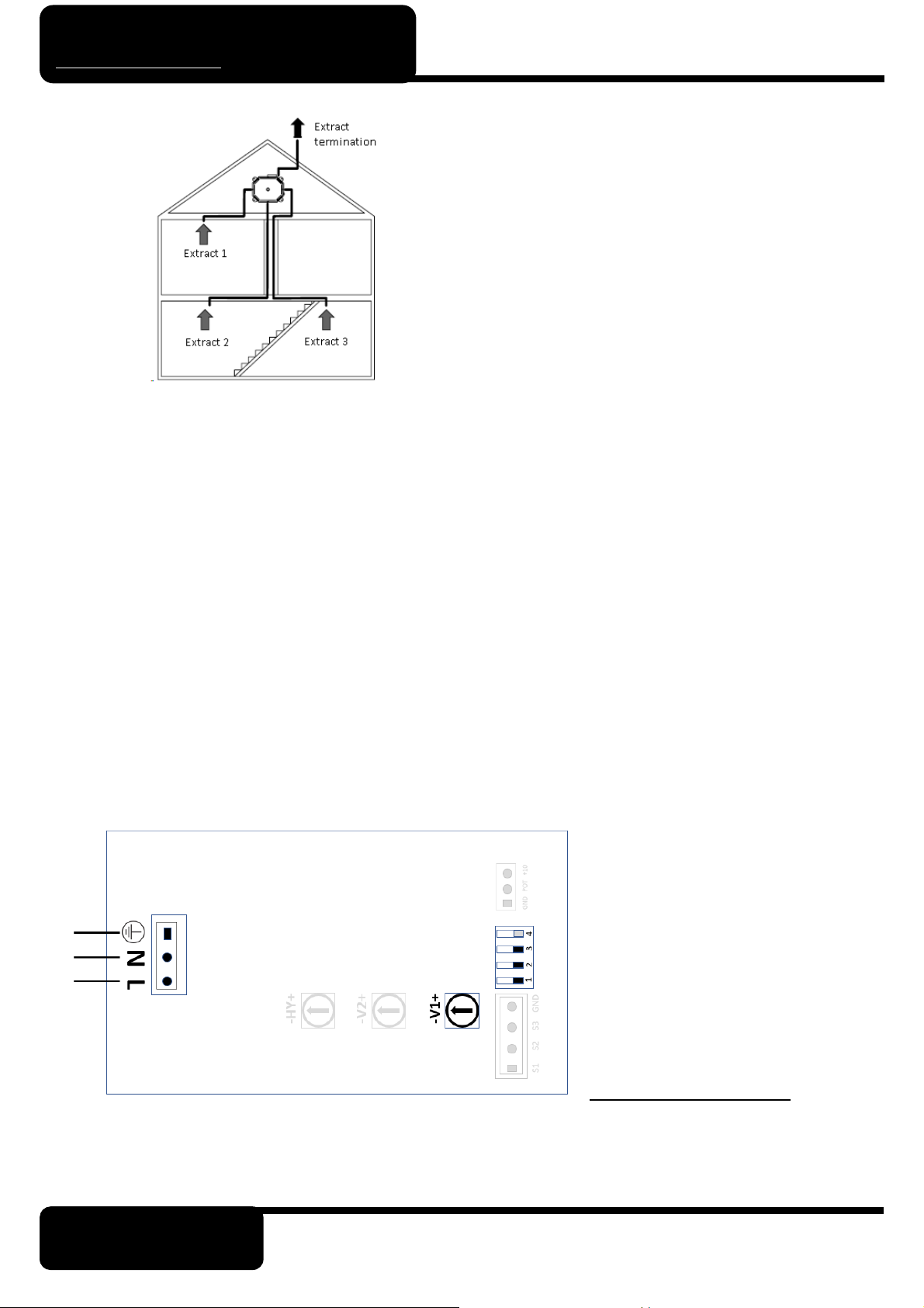
The PHS MEV is a whole house mechanical extract fan designed to be connected to ceiling extracts valves
as per buildings regulations part F. Suitable for above ceiling, false-ceiling or floor installation, horizontally
or vertically. This version is with integral humidistat.
3.0 Technical Specifications
1. Outer fan casing manufactured from powder coated galvanised sheet steel.
2. Top cover made from strong ABS plastic.
3. Internal self-extinguishing acoustic foam lining.
4. EC external rotor motor for energy saving, mounted on ball bearings that guarantee a longer
product life cycle and suitable for cold climates.
5. Forward curved centrifugal impeller to provide a smooth and silent airflow through the unit.
6. Provided with multiple extract points:
a. air exhaust to outside -through 1xØ125mm circular spigot
b. air extract from inside -through 4xØ125mm circular spigots.
7. IPX2 protection.
8. Power supply 230V~ 50/60Hz.
Model Airflow
m
³/h max
Static Pressure
Pa max
Power
W max
Sound Pressure
dB(A) @3m
PHS MEV
380
219
36
27

Page | 3 Rev: 210301
AFTER INSTALLATION THE END USER SHOULD
KEEP THIS GUIDE FOR FUTURE REFERENCE
DO NOT THROW AWAY
SHOULD YOU ENCOUNTER ANY
PROBLEMS INSTALLING THIS
UNIT, CALL US: 021 4875297
4.0 Operation
Single speed operation
The unit runs at the speed set by turning the integral trimmer “V1” in the terminal box. This is the default
factory setting.
Wiring diagram: Fig. 5A - Dip switch configuration: 0000 (Fig. 5F).
Two speed operation
The unit runs continuously at the speed set by turning the integral trimmer “V1” in the terminal box and
can be boosted at high speed, which is set by turning the integral trimmer “V2” in the terminal box.
Boost is activated, when needed, by means of a remote two-position switch (not supplied) or by means of
remote sensors SEN-PIR which is available on request.
Wiring diagram: Fig. 5B - Dip switch configuration: 1000 (Fig. 5F).
Variable speed operation with CTRL remote manual controller (accessory on request)
The unit runs at the speed set by turning the knob of the CTRL remote manual control panel (accessory,
Fig. 6). Wiring diagram: Fig. 5C - Dip switch configuration: 0100 (Fig. 5F).
Variable speed operation through a domotic (BMS) system or ballast potentiometer.
The unit runs at the speed set by turning the knob of an external 1-10V ballast potentiometer or set by an
external 1-10V signal from a domotic (BMS) system.
Wiring diagram: Fig. 5D - Dip switch configuration: 0110 (Fig. 5F).
Three speed operation with SEL speed selector (accessory on request).
The unit runs at the speed selected by turning the knob of the SEL speed selector (See figure 7.)Speed 1 is
set by turning the integral trimmer “V1” in the terminal box.
Speed 2 is set by turning the integral trimmer “V2” in the terminal box.
Speed 3 is the maximum speed achievable by the unit.
Wiring diagram: Fig. 5E - Dip switch configuration: 1000 (Fig. 5F).
Humidity Control Functions
Whatever is the chosen operation and the speed setting, when the humidity threshold is reached, the fan
speed is increased by 15%.
When the humidity level returns below the threshold, the fan continues to run at increased speed for a pre-
set period of time.
Humidity threshold is adjustable from 50% to 95% via trimmer HY (Fig. 5G). To deactivate the humidistat
function, turn the trimmer HY completely clockwise (position G).
NOTE: Dip switch number 4 should always be in “0” position to enable humidistat function.
5.0 Maintenance
Make sure the mains supply of the unit is disconnected before performing any maintenance. The
maintenance must be carried out by a qualified technician and in accordance with local rules and
regulations.

Page | 4 Rev: 210301
AFTER INSTALLATION THE END USER SHOULD
KEEP THIS GUIDE FOR FUTURE REFERENCE
DO NOT THROW AWAY
SHOULD YOU ENCOUNTER ANY
PROBLEMS INSTALLING THIS
UNIT, CALL US: 021 4875297
6.0 Disposal and recycling
8.0 Dimensions
Weight = 6.4kg
Bottom View Side Elevation Side Elevation
9. Installation and Commissioning
a) Locate the unit in any of the following locations:
•Loft space
•False ceiling
•Cupboard
b) Ensure there are allowance made to remove the top cover and easy connection of the various pipes.
c) The unit must be screwed to a secure base. The extract points duct runs should be well planned, any
ducting outside on the warm envelope needs to be insulated. Fit a suitable low resistance external
extract termination (e.g. a suitable roof vent or fixed louvre grill)
d) Fit adjustable extract valves in the chosen room locations.
e) The pipe dimensions and room flow rates shall be designed by Passive House Systems engineers.
This product complies with EU Directive 2002/96/EC. The symbol of the
crossed-out dustbin indicates that this product must be collected separately
from other waste at the end of its life. The user must, therefore, dispose of the
product in question at suitable electronic and electro-technical waste disposal
collection centres, or else send the product back to the retailer when
purchasing a new, equivalent type device. Separate collection of
decommissioned equipment for recycling, treatment and environmentally
compatible disposal helps to prevent negative effects on the environment and
on health and promotes the recycling of the materials that make up the
equipment. Improper disposal of the product by the user may result in
administrative sanctions as provided by law.

Page | 5 Rev: 210301
AFTER INSTALLATION THE END USER SHOULD
KEEP THIS GUIDE FOR FUTURE REFERENCE
DO NOT THROW AWAY
SHOULD YOU ENCOUNTER ANY
PROBLEMS INSTALLING THIS
UNIT, CALL US: 021 4875297
f) With the mains supply isolated, wire the unit to the local isolator in accordance with local regulations.
g) All maintenance and building works should be complete before commissioning this MEV unit. This
will avoid any major disturbance to the installation or high volumes of dust or debris being drawn
into the system. Do not commission the MEV unit until it is fully installed including power, ductwork,
internal valves and external vents.
h) MEV systems must be commissioned in accordance with Approved Document F of the Building
Regulations. Further good practice and advice for the installation of MEV systems can be found in
the latest edition of the Domestic Ventilation Compliance Guide for England and Wales. For MEV
commissioning guidance in other countries, please refer to the relevant local Building Regulations
for that country.
i) Determine the required ventilation rates. For guidance see Approved Document F of the building
regulations.
j) Fully open all extract valves then measure the air flow rate at all system extract points using a cali-
brated air flow meter capable of measuring in l/s or m
3
/hr.
k) Add the extract rates from all rooms together then compare this value to the calculated whole building
(boost) extract ventilation rate.
10. Electrical Wiring
The unit must be earthed
Figure 5A Single Speed Operation
Ductwork should be fitted in accordance with the
Domestic Ventilation Compliance Guide and follow
any system designs that have been produced for the
property/
Ductwork to atmosphere or through unheated spaces
should be insulated.
For efficiency, all ductwork should be as large a
diameter as possible.
Inline filters should be fitted and maintained to prevent
soiling of the ducts.

Page | 6 Rev: 210301
AFTER INSTALLATION THE END USER SHOULD
KEEP THIS GUIDE FOR FUTURE REFERENCE
DO NOT THROW AWAY
SHOULD YOU ENCOUNTER ANY
PROBLEMS INSTALLING THIS
UNIT, CALL US: 021 4875297
Figure 5B Two speed operation
Figure 5C Variable speed operation with manual controller
Figure 5D Variable speed operation through external domotic (BMS) systems or ballast potentiometer.

Page | 7 Rev: 210301
AFTER INSTALLATION THE END USER SHOULD
KEEP THIS GUIDE FOR FUTURE REFERENCE
DO NOT THROW AWAY
SHOULD YOU ENCOUNTER ANY
PROBLEMS INSTALLING THIS
UNIT, CALL US: 021 4875297
Figure 5E Three speed operation with SEL wired speed selector.
11. Fan Speed Settings

Page | 8 Rev: 210301
AFTER INSTALLATION THE END USER SHOULD
KEEP THIS GUIDE FOR FUTURE REFERENCE
DO NOT THROW AWAY
SHOULD YOU ENCOUNTER ANY
PROBLEMS INSTALLING THIS
UNIT, CALL US: 021 4875297
SAP Appendix Q Test Results.
12. Humidistat Settings
The PHS_MEV_H machine operates at a continuous normal air flow rate setting. The unit fan
speed will increase if the unit detects a rise in humidity levels in the property. The reaction
thresholds to various humidity levels can be varied by ad usting the trimmer HY.
Figure 5G
CTRL SEL

Page | 9 Rev: 210301
AFTER INSTALLATION THE END USER SHOULD
KEEP THIS GUIDE FOR FUTURE REFERENCE
DO NOT THROW AWAY
SHOULD YOU ENCOUNTER ANY
PROBLEMS INSTALLING THIS
UNIT, CALL US: 021 4875297
13. ErP Directive
a)
Marking
-
Passive House Systems
b)
Model
-
PHS MEV
c)
SEC Class
-
D
C
1
)
SEC Warm Climates
kWh/m
²
.a
-
8.9
C
2
)
SEC Average Climates
kWh/m
²
.a
-
20.9
C
3
)
SEC Cold Climates
kWh/m
²
.a
-
41.9
Energy
Label
-
Yes
d)
Unit Typology
-
Residential
-
unidirectional
e)
Type of drive
-
Variable speed drive
f)
Type of heat recovery system
-
Absent
g) Thermal efficiency of heat
recovery
% Not applicable
h)
Maximum flow rate
m
³
/h
230
i) Electrical power input at max flow
rate
W 36
j)
Sound power level (Lwa)
dBA
42
k)
Reference flow rate
m
³
/h
161
l)
Reference pressure difference
Pa
50
m)
Specific power input
W/m
³
/h
0.043
n
1
)
Control factor
-
0.85
n2)
Control typology
-
Central demand
control
o
1
)
Max internal leakage rate
%
N/A
o
2
)
Max external leakage rate
%
N/A
p
1
)
Internal mixing rate
%
N/A
p
2
)
External mixing rate
%
N/A
q)
Visual filter warning
-
N/A
r) Instructions to install regulated
grilles
- Reference instruction booklet
s)
Internet for instruction
-
www.passivehousesystems.com
t)
Airflow sensitivity to pressure
%
N/A
u)
Indoor/outdoor air tightness
m
³
/h
N/A
v
1
) AEC -Annual electricity
consumption (Warm Climates)
KWh 0.4
V
2
) AEC -Annual electricity
consumption (average Climates)
KWh 0.4
v
1
) AEC -Annual electricity
consumption (Cold Climates)
KWh 0.4
w
1
) AHS -Annual heat saved (Warm
Climates)
KWh 9.9
W
2
)
AHS -Annual heat saved (Average
Climates)
KWh 21.9
w
1
) AHS -Annual heat saved (Cold
Climates)
KWh 42.9
Sound Pressure @3m, 40%
dB(A)
14
Ambient Temperature °
C
+40
Degree of Protection
-
X2
Marking
-
CE

Page | 10 Rev: 210301
AFTER INSTALLATION THE END USER SHOULD
KEEP THIS GUIDE FOR FUTURE REFERENCE
DO NOT THROW AWAY
SHOULD YOU ENCOUNTER ANY
PROBLEMS INSTALLING THIS
UNIT, CALL US: 021 4875297
14. Warranty
We appreciate you choosing this quality product. We are confident that you will be delighted with the per-
formance of the system and the resulting improvement in air quality in your home after it has been installed.
This unit is covered by a 2-year warranty. You should not dismantle or remove any parts of the product other
than those instructed in this guide. Tampering with the unit will void the warranty. The valves should be
checked periodically to ensure there is air flowing through the system.
Passive House Systems Supply & Installation
If your product has been supplied and installed by Passive House System or an authorised agent it is covered
with a two-year parts and labour warranty. If you detect a fault, please contact us on 021 4875297. You will
be given guidance over the phone, or an arrangement may be made for a member of our team to visit (call-
out charges may apply if a fault cannot be identified).
Supply Only
If your product has been supplied by Passive House System and installed by a third party it is covered by a
two-year parts only warranty. If you detect a fault and the product has been installed in accordance to the
fitting/wiring instructions, relevant guidance documents and by a competent and qualified person (proof may
be required), please return the product to the place of purchase for a replacement.
Warranty Conditions & Exclusions
Please note that a receipt will be required as proof of purchase. Products bought from an unapproved source,
including but not limited to auction websites, are not covered by the warranty.
1The system must be correctly installed and operated according to the instructions contained in the
user guide supplied.
2The warranty will be rendered invalid if the system has been serviced, maintained, repaired, taken
apart or tampered with by any person not authorized, which in any way contradicts the instruction guide set
out by Passive House Systems
3The warranty does not cover accidental damage, misuse or abuse.
4The warranty is in addition to your statutory or legal rights.
Your unit serial number __________________________
For warranty conditions and exclusions, visit www.passivehousesystems.ie/warranty.
Installer Details (PRINTED)
I
nstaller Name
C
ompany Name
Telephone No.
I
nstallation Date
Passive House Systems (IRL) Passive House Systems (PHS) Gmbh
Unit 5B4. Industrie Strasse 8.
Link Road Business Park 97483
Ballincollig Eltmann
Co. Cork. P31W950 Deutschland
Tel: 021 487 5297 Tel: 09522 708 918
Email: Info@passivehousesystems.ie Email: Info@passivehousesystems.de
Table of contents
Popular Fan manuals by other brands

Ebmpapst
Ebmpapst S6E710-AR03-01 operating instructions

Ebmpapst
Ebmpapst A2D300-AP06-14 operating instructions

Bionaire
Bionaire BTF4310AR Instruction leaflet

aldes
aldes inoVEC standard Assembly instructions

BLAUBERG Ventilatoren
BLAUBERG Ventilatoren Cabrio Base 100 user manual

OSTBERG
OSTBERG LPKB 4" B UL instructions for installation and directions for use

BLAUBERG
BLAUBERG Sileo DC 100 user manual

Spencer
Spencer 190 Instruction and maintenance manual

Ruck Ventilatoren
Ruck Ventilatoren EL EC Series Assembly instruction

Merra
Merra CFN-1052 instruction manual

York
York YEFB Series Installation and operation manual

Vortice
Vortice VORT QUADRO MICRO 100 I Instruction booklet