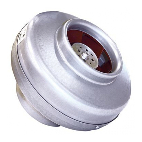
OSTBERG LPKB 4" B UL Manual

UL VERSION
Installation and
directions for use
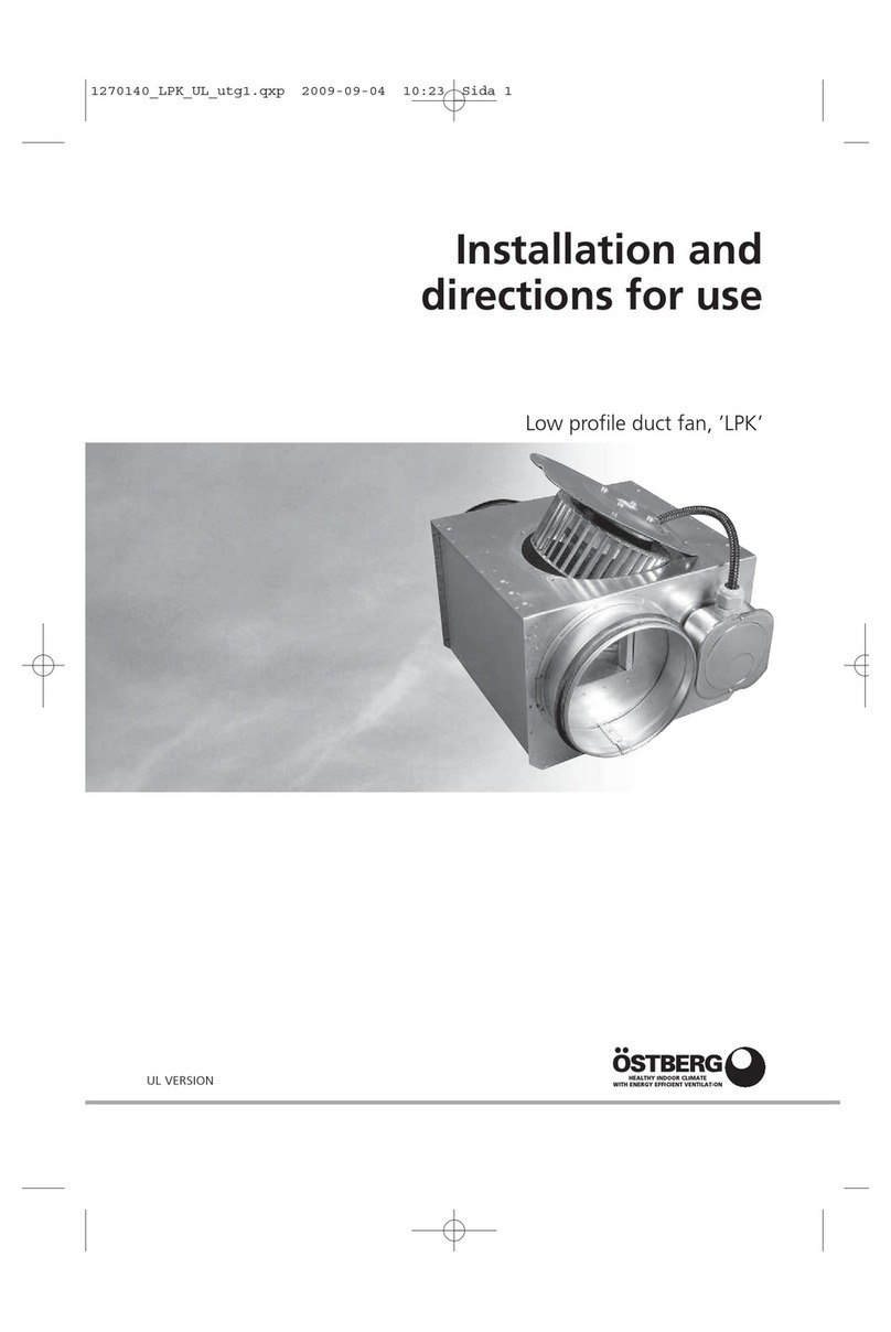
Low profile duct fan, ’LPKB’ UL

This directions for use contains the following product:
Low profile in line duct fan ’LPKB’
Read and save these directions.
INSTALLATION
DESCRIPTION
• The fan is used for transportation of ”clean” air,
meaning not intended for fire-dangerous substan-
ces, explosives, grinding dust, soot, etc.
• The fan is equipped with an asynchronous external
rotor induction motor with maintenance-free
sealed ball-bearings.
• To achieve maximum life length for installations in
damp or cold environments, the fan should be ope-
rating continuously.
• The fan can be installed outside with a weather
protecting cover or in damp environments. Make
sure that the fan-house is equipped with drainage.
• All ’LPKB’-fans are as standard, single phase 110-127
V 60 Hz.
• The fan can be installed vertically or horizontally.
• The fan is UL 705 ”Power Ventilators” approved,
E224370.
• The fan has rotating parts, therefore safety precau-
tions should be exercised during installation, opera-
tion and maintenance. Tighten all screws before
operation unit. USE HAND PROTECTION AND
STAY CLEAR OF SHARP EDGES.
• The fan must be installed according to all local and
national codes and the air direction label on the
fan.
• The fan must be connected to duct or equipped
with a safety grill.
• The fan should be installed in a safe way not to
cause vibrations or risking the fan to fall off.
• The junction box must be security fasten to the fan
with 2 screws.
• Ensure that the fan and junction box are easily
accessible for service after the installation.
• A wiring diagram is applied on the inside of the
junction box.
• Use this unit only in the manner intended by the
manufacturer. If you have any questions, contact
your manufacturers representative.
• Before servicing and cleaning unit, switch power
off at service panel and lock the service disconnec-
ting means to prevent power from being switched
on accidentally. When the service disconnecting
means cannot be locked, securely fasten a promi-
nent device, such as a tag, to the service panel.
• Installation work and electrical wiring must be
done by qualified person(s) in accordance with all
applicable codes and standards, including fire-rated
construction.
• When cutting or drilling into the wall or ceiling, do
not damage electrical wiring or other hidden utili-
ties.
• Ducted fans must always be ventilated to the out-
doors.
CAUTION! FOR GENERAL VENTILATION USE ONLY. DO NOT USE TO EXHAUST HAZARDOUS
OR EXPLOSIVE MATERIALS AND VAPORS.
WARNING! TO REDUCE THE RISK OF FIRE, ELECTRICAL SHOCK OR INJURY TO PERSONS,
OBSERVE THE FOLLOWING:
2

3
Mount the junction box on the fan acc. picture.
Use the enclosed screws located in
the junction box.
INSTALLATION INSTRUCTIONS
Exhaust
system
Exhaust system for ceiling
Exhaust system
The ‘LPKB’-fan can easily be mounted using the
three brackets, in any position.
Installation instructions of exhaust systems for duct fan ‘LPKB’.

OPERATION
• Do not install this unit above a tub or a shower, if
it’s not marked as appropriate for the application.
•Never place a switch where it can be reached from
a tub or shower.
Before starting, make sure that:
• the fan is installed and electrically connected in the
correct way to ground.
4
MAINTENANCE
should be done without dislodging or damaging the
impeller.
• Make sure that there is no noise from the fan.
1. Make sure that there is electrical power to the fan.
2. Cut the electrical power and verify that the im-
peller is not blocked.
3. Check the thermo-contact/motor protector. If it is
disconnected the cause of overheating must be
located and taken care of.
4. ’LPKB’ is equipped with automatic thermo-protec-
tor which resets automatically when the motor is
back in normal working temperature.
5. Make sure that the capacitor is connected accor-
ding to the wiring diagram.
6. If the fan still does not work, the first thing to do is
to change the capacitor.
7. If nothing of this works, contact your fan supplier.
FAULT DETECTION
• the current does not exceed more than +5% of
what is stated on the label.
• No foreign object are placed in the fan and no
noise appears when starting the fan.
• Use this unit only in the manner intended by the
manufacturer. If you have any questions, contact
your manufacturers representative.
• Before service and cleaning of the unit, switch off
the power at the service panel and lock the service
disconnecting means to prevent power from being
switched on accidentally. If the service disconnec-
ting means cannot be locked, securely fasten a pro-
minent device, such as a tag, to the service panel.
• Consider the weight of the fan when removing lar-
ger fans to avoid jamming and contusions.
• The fan must be cleaned when needed, at least
once per year to maintain the capacity and to avoid
unbalance which may cause unnecessary damages
on the bearings.
• The fan bearings are maintenance-free..
• When cleaning the fan, high-pressure cleaning or
strong dissolvent must not be used. Cleaning
WARNING! TO REDUCE THE RISK OF FIRE, ELECTRICAL SHOCK OR INJURY TO PERSONS,
OBSERVE THE FOLLOWING:
If repair must be made to the product, it has to be performed by a qualified maintenance person.
The fan is easy to open for cleaning
and service with the swing-out
design.
Loosen the screws a few turns,
without removing them.
Turn the motor bracket to the right
so the screws can go through the
key holes. Open the motor bracket.
When closing, turn the motor
bracket to the left so the screws
go into the smaller part of the
keyholes.
Tighten the screws.
OPEN
OPEN
CLOSE
CLOSE

WIRING DIAGRAMS
No: 4040001 No: 4040002
5
1~
1~
TECHNICAL DATA
Voltage Current Power Speed Weight Wiring Capacitor Insulation Motor
V/Hz A W rpm lbs/kg diagram μF class, motor protection
LPKB 4” A UL 115/60 0.37 42 1770 11.24 / 5.10 4040002 14 F IP 44
LPKB 4” B UL 115/60 0.64 70 2650 11.24 / 5.10 4040001 8 F IP 44
LPKB 5” A UL,
LPKB 5”+2x4” A UL 115/60 0.37 42 1740 11.90 / 5.40 4040002 14 F IP 44
LPKB 5” B UL,
LPKB 5”+2x4” B UL 115/60 0.65 71 2600 11.90 / 5.40 4040001 8 F IP 44
LPKB 6” B UL,
LPKB 6”+2x5” B UL 115/60 0.66 74 2520 15.32 / 6.95 4040001 8 F IP 44
LPKB 6” C UL,
LPKB 6”+2x5” C UL 115/60 1.15 132 2540 15.76 / 7.15 4040001 10 F IP 44
LPKB 8” A UL 115/60 1.24 142 2650 17.53 / 7.95 4040001 10 F IP 44

SOUND DATA
6
LPKB 4” A UL
115 V, 87 CFM, 0.36 H2OL
pA LwA tot dB (A) 63 125 250 500 1K 2K 4K 8K
Environment 43 50 28 30 48 41 40 39 31 29
Inlet 58 42 50 53 53 47 45 40 28
Outlet 60 484955 5451504431
90 V, 59 CFM, 0.18 H2OL
pA LwA tot dB (A) 63 125 250 500 1K 2K 4K 8K
Environment 35 42 28 28 38 34 34 35 28 29
Inlet 50 36 44 45 44 39 38 34 16
Outlet 52 404344 4544434019
70 V, 40 CFM, 0.10 H2OL
pA LwA tot dB (A) 63 125 250 500 1K 2K 4K 8K
Environment 32 39 26 26 34 28 31 32 28 29
Inlet 44 30 35 39 37 32 38 29 12
Outlet 47 354039 3839403515
LPKB 4” B UL
115 V, 127 CFM, 0.80 H2OL
pA LwA tot dB (A) 63 125 250 500 1K 2K 4K 8K
Environment 47 54 33 37 51 48 47 43 36 32
Inlet 68 52 60 63 64 57 55 50 46
Outlet 70 575862 6563595449
90 V, 100 CFM, 0.52 H2OL
pA LwA tot dB (A) 63 125 250 500 1K 2K 4K 8K
Environment 43 50 29 33 47 43 42 39 31 29
Inlet 64 46 54 62 57 51 49 42 36
Outlet 66 515463 5957534840
70 V, 70 CFM, 0.28 H2OL
pA LwA tot dB (A) 63 125 250 500 1K 2K 4K 8K
Environment 37 44 27 30 40 36 36 34 28 29
Inlet 53 40 46 48 49 43 39 33 21
Outlet 55 444947 5047443926
LPKB 5” A UL, LPKB 5”+2x4” A UL
115 V, 87 CFM, 0.44 H2OL
pA LwA tot dB (A) 63 125 250 500 1K 2K 4K 8K
Environment 39 46 28 30 42 39 40 39 29 29
Inlet 59 43 52 55 53 47 45 40 29
Outlet 60 475156 5450484432
90 V, 59 CFM, 0.22 H2OL
pA LwA tot dB (A) 63 125 250 500 1K 2K 4K 8K
Environment 34 41 26 26 36 33 35 35 28 29
Inlet 51 36 45 44 45 40 40 33 19
Outlet 52 394645 4542413721
70 V, 44 CFM, 0.12 H2OL
pA LwA tot dB (A) 63 125 250 500 1K 2K 4K 8K
Environment 31 38 26 24 30 27 31 32 28 29
Inlet 45 29 36 37 38 34 40 28 14
Outlet 46 343938 3836403517

SOUND DATA
7
LPKB 5” B UL, LPKB 5”+2x4” B UL
115 V, 146 CFM, 0.80 H2OL
pA LwA tot dB (A) 63 125 250 500 1K 2K 4K 8K
Environment 47 54 31 39 50 49 47 42 35 32
Inlet 68 51 60 63 64 56 53 51 47
Outlet 70 566162 6662585649
90 V, 117 CFM, 0.48 H2OL
pA LwA tot dB (A) 63 125 250 500 1K 2K 4K 8K
Environment 42 49 28 34 44 43 41 38 30 29
Inlet 62 45 54 58 58 50 47 43 37
Outlet 65 505561 5955514940
70 V, 91 CFM, 0.24 H2OL
pA LwA tot dB (A) 63 125 250 500 1K 2K 4K 8K
Environment 38 45 26 33 42 37 37 34 28 29
Inlet 54 39 49 49 50 42 40 33 24
Outlet 55 425047 5046433826
LPKB 6” B UL, LPKB 6”+2x5” B UL
115 V, 157 CFM, 0.80 H2OL
pA LwA tot dB (A) 63 125 250 500 1K 2K 4K 8K
Environment 46 53 33 39 49 49 43 42 34 31
Inlet 68 51 58 65 61 56 51 51 46
Outlet 70 565966 6559565547
90 V, 123 CFM, 0.50 H2OL
pA LwA tot dB (A) 63 125 250 500 1K 2K 4K 8K
Environment 42 49 29 36 47 42 38 37 29 29
Inlet 64 46 52 62 56 50 45 44 36
Outlet 64 505262 5851494737
70 V, 93 CFM, 0.26 H2OL
pA LwA tot dB (A) 63 125 250 500 1K 2K 4K 8K
Environment 35 42 26 33 38 35 32 33 28 29
Inlet 54 40 47 50 48 41 38 34 21
Outlet 56 444851 5143414124
LPKB 6” C UL, LPKB 6”+2x5” C UL
115 V, 233 CFM, 1.00 H2OL
pA LwA tot dB (A) 63 125 250 500 1K 2K 4K 8K
Environment 52 59 34 50 53 55 49 46 40 33
Inlet 74 54 62 69 71 64 56 57 46
Outlet 76 606268 7466636351
90 V, 191 CFM, 0.56 H2OL
pA LwA tot dB (A) 63 125 250 500 1K 2K 4K 8K
Environment 47 54 30 49 48 48 42 40 33 30
Inlet 67 49 60 63 62 56 48 48 35
Outlet 69 535863 6558565440
70 V, 121 CFM, 0.30 H2OL
pA LwA tot dB (A) 63 125 250 500 1K 2K 4K 8K
Environment 43 50 27 45 47 39 35 36 28 29
Inlet 60 43 52 57 54 48 39 36 26
Outlet 62 485658 5549454225

SOUND DATA
8
LPKB 8” A UL
115 V, 316 CFM, 0.80 H2OL
pA LwA tot dB (A) 63 125 250 500 1K 2K 4K 8K
Environment 53 60 33 44 52 58 49 46 41 32
Inlet 76 54 62 69 73 64 62 60 50
Outlet 79 546269 7364626050
90 V, 252 CFM, 0.50 H2OL
pA LwA tot dB (A) 63 125 250 500 1K 2K 4K 8K
Environment 48 55 28 39 48 53 42 40 34 29
Inlet 70 50 59 64 67 57 55 52 39
Outlet 71 535865 6860615642
70 V, 165 CFM, 0.26 H2OL
pA LwA tot dB (A) 63 125 250 500 1K 2K 4K 8K
Environment 40 47 25 41 44 40 34 31 28 28
Inlet 61 43 53 58 56 48 44 42 24
Outlet 63 475259 5851524628
The sound data have been compiled by means of sound
measurements methods as follows:
Pressure and drop: ISO 5801.
Determination of acoustic sound level in duct:
EN ISO 5136.
Determination of acoustic sound level in reverberation
room: EN ISO 3741.
DESIGNATIONS
LwATot: Total A-weighted sound power level dB(A)
(ref 10-12W)=the sum of the sound power level in the
octave ranges.
LwA: A-weighted sound power level in octave range
dB(A)(ref 10-12W).
LpA: A-weighted sound pressure level in dB(A) accor-
ding to normed A-weightening correction and relating
to an effective absorption area of 20 m2with half sphe-
rical translation at a distance of 3 metres.

9
PRESSURE AND FLOW DIAGRAMS
LPKB 4”A UL
PRESSURE/FLOW
LPKB 4”B UL
PRESSURE/FLOW
LPKB 5”A UL, LPKB 5”+2x4”A UL
PRESSURE/FLOW
LPKB 5”B UL, LPKB 5”+2x4”B UL
PRESSURE/FLOW
POWER/FLOW POWER/FLOW
POWER/FLOW POWER/FLOW

10
PRESSURE AND FLOW DIAGRAMS
LPKB 6”B UL, LPKB 6”+2x5”B UL
PRESSURE/FLOW
LPKB 6”C UL, LPKB 6”+2x5”C UL
PRESSURE/FLOW
LPKB 8”A UL
PRESSURE/FLOW
POWER/FLOW POWER/FLOW
POWER/FLOW

DIMENSIONS Inch (mm)
LPKB 4”A UL, LPKB 4”B UL
LPKB 5”A UL, LPKB 5”B UL
LPKB 5”+2x4 A UL, LPKB 5”+2x4 B UL
11

DIMENSIONS Inch (mm)
LPKB 6”A UL, LPKB 6”C UL
LPKB 6”+2x5 A, LPKB 6”+2x5 C
LPKB 8”A UL
12

1270343 Utg. 2
OSTBERG AMERICAS INC.
55 Raglin PL # 3 • Cambridge, N1R 7J2 • Canada
Phone 519-623-6363 • Telefax 519-623-8543
www.ostberg.com
This manual suits for next models
7
Table of contents
Other OSTBERG Fan manuals
OSTBERG
OSTBERG CONNECTION BOX 70 K User manual

OSTBERG
OSTBERG RKX 500x250 D3 Manual
OSTBERG
OSTBERG RF User manual
OSTBERG
OSTBERG CF 180 C Manual

OSTBERG
OSTBERG CV Manual

OSTBERG
OSTBERG RS Manual

OSTBERG
OSTBERG SAU EC Series Programming manual
OSTBERG
OSTBERG HERU S AC Series Manual

OSTBERG
OSTBERG RS Owner's manual

OSTBERG
OSTBERG LPKB Series Manual
Popular Fan manuals by other brands

Helios
Helios GigaBox GBW EC 355 T120 Installation and operating instructions

DeWalt
DeWalt DXF2035 Original instructions

Schako
Schako NOVENCO NOVAX ACN ATEX Series Installation and Maintenance

Litex Industries
Litex Industries GA24BNK6L installation guide
KDK
KDK 20RGF Service manual
Hunter
Hunter Caribbean Breeze 54095 installation manual
