Patlite LA6-POE User manual

Signal Tower
Operation Manual
Model LA6-POE
B95100524_01

2
Signal Tower LA6-POE Operation Manual
Table of Contents
1. Introduction 5
2. Model Number Conguration 7
3. Installation 9
4. How to Operate 15

3
Signal Tower LA6-POE Operation Manual
5. Operating Procedure 32

4
Signal Tower LA6-POE Operation Manual
6. Maintenance 70
7. Troubleshooting 83
8. Replacement Parts 86
9. Option Parts 87
10. General Specications 89
5
Signal Tower LA6-POE Operation Manual
1. Introduction
Thank you very much for purchasing our PATLITE product.
• Request the installation and wiring be performed by a professional contractor if construction work is involved.
• Prior to installation, read this manual thoroughly before using this product to ensure correct use.
• After reviewing this manual, if there are any questions regarding this product, please contact the nearest PATLITE oce
listed on the back cover of this manual.
Notice
• The copyrights of this book is owned by the PATLITE Company, Inc. (henceforth referred to as "our company"). Any
reproduction, duplication, alteration, or extracting portions of this book, etc., without written permission from our
company is forbidden.
• Specications, the design, and other contents written in this book may be changed for improvements without Prior
notice and may result in dierences from the actual product purchased.
• This product meets severe quality control and inspection requirements prior to shipment, but if some failure or defect
is found, please contact the place of purchase, or your PATLITE Sales Representative (indicated on the last page) to
solve the issue.
• Please understand that our company does not take any responsibility for damage and other disadvantages this
product (software is included) has caused due to the customer using this product outside its designed application,
such as for home, oce and industrial use, high security applications such as medical or systems related to human
life, directly or inderectly, or from claims from any third parties.
Also understand, prior to use, no responsibility is taken at our company for damages or other disadvantages, due
to customers use of this product beyond the scope of its general application, or from any claims made from third
parties.
When using this product for applications in which equipment of higher reliability than the general application
demands, such as a computer system, etc., please use suitable safety design countermeasures against system failure,
etc.
• Please understand that our Company does not take any responsibility for damage and other disadvantages this
product (software is included) has caused due to the customer using this product, or any claims from third parties.
1.1. Safety Precautions
• In order to prevent any damage to the user and other personnel or to assets, note the following:
• The following symbol classies and explains the level of harm inicted when caution is disregarded while using the
product.
!WARNING This symbol indicates an imminently dangerous condition: failure to follow the instructions may
lead to death or serious injury.
!CAUTION This symbol indicates a potentially dangerous condition: failure to follow the instructions may lead
to slight injury or property damage.
!NOTICE Indicates something to observe before using this product. The disregard to this indication may lead
to product malfunction or failure.
Meaning of the symbols
Degree Symbol Contents
Prohibited Indicates it is forbidden.
Caution !Indicates to show caution.
Directions !Indicates when a procedure must be performed.
Description MEMO Indicates a supplementary explanation.
6
Signal Tower LA6-POE Operation Manual
1.2. For safe application, observe the following:
!WARNING
To prevent from shock, short-circuits or damage, observe the following:
• Be sure the power is disconnected before replacement (fuse exchange, etc.) or repair.
• Use this product in a properly maintained condition. (Replace or repair if the body, LED unit, etc. are damaged.)
Request the installation and wiring be performed by a professional contractor if construction work is involved. Failure
to comply may result in re, electric shock or falling from high places may occur.
!CAUTION
Do not listen to a buzzer at close range. Failure to observe this may lead from irritation to permanent damage to the
ears.
In order to maintain protection of this product against dust and waterproong performance, be sure to use the head
cover, buzzer unit, USB cover and LAN Bracket in the condition that it was originally attached. (
TN
Direct Mount Type)
Do not operate this product with the‘O’ring or waterproof packing removed. Waterproof performance will drop and
possibility cause failure. (
TN
Direct Mount Type)
By all means, do not apply voltage to the Common wire (COM) or Flashing Common line. Product failure will occur.
When removing covers or packing from the equipment, which is attached to this product, be careful not to snag the
product. Failure to comply may result in damage to the product.
Do not drop, or allow this product to fall. Failure to comply may result in damage to the product.
!NOTICE
To ensure proper safety while using the signal tower, observe the following:
• Perform periodic pre-maintenance.
• As a precaution against problems occurring, Use this product together with other equipment.
Be sure to discharge any static electricity from the body before handling static sensitive parts of this product.
(To prevent damage from static electricity, touch hands or other body parts to metals or an earth ground to discharge
the body from static charge.)
Use a soft cloth, etc., dampened with water to wipe the main signal tower unit.
(Do not use cleaners containing chemicals such as thinner, alcohol, gasoline or oil.)
To ensure safety when this product is installed onto equipment, observe the following:
• Do not remove parts beyond those designed to be removed from this product.
• Do not modify or disassemble this product.
• Use only the specied replacement parts listed in comprehensive manual.
Contrary to Warnings and Cautions indicated in this document, product failure due to mishandling, disassembly,
modications or natural disasters, etc. is not covered by any Warranty.
Moreover, avoid any applications outside those indicated in this document.
1.3. Product Features
This product has a new "Smart Mode" function; in addition to the"Signal Tower Mode", which can directly control the LED
and buzzer like a standard signal tower. In the "Smart Mode", various displays can be shown, such as a slow ashing rate,
simulating that of a rey and a display that can be used as a level meter.
In addition to the signal line input control, since it is compatible with the Power over Ethernet (henceforth, PoE), it can be
operated through a LAN Cable to acquire signal tower status conditions via the network, and control it in the Signal Tower
Mode or Smart Mode. Also, this product can use the mirroring function, in which one signal tower can show the same status
as the other, but in a dierent location.
Since the Signal Tower is the LA6, the dedicated application software, "EDITOR for LA series" can be used to reect the
setting data via the network.
* Visit our company's home page and download the latest application software for free.
1.4. Trademarks
Internet Explorer is a trademark or registered trademark of Microsoft Corporation.
Google Chrome is a trademark or registered trademark of Google Inc.

7
Signal Tower LA6-POE Operation Manual
2. Model Number Conguration
2.1. Model Number Conguration
Model
Number
↓
D BW5
LA6-
Model
-POE
Extended
Functionality
LED
Tiers
W
Body
Color
Rated
Voltage
Flashing/
Buzzer
Mounting
Specifications
Off-white B
SN
TN Direct Mount
Stationary Flashing/Buzzer
Rated voltage: DC24V.
Common to all models
Common to all models
Common to all models
Common to all models
PoE Supported
8
Signal Tower LA6-POE Operation Manual
2.2. Part Names and Dimensions
<LA6-5DTNWB-POE> <LA6-5DSNWB-POE>
Headcover
(Multi-function Button
Inside →※1)
LED Unit
LAN Bracket
Stand Cover
Base Plate
φ60
145
USB Cover
(In Back) ※2
428
16
228
φ60
70
110
405
16
25
8
LAN Unit
“Clear” Switch
Nameplate
(Backside)
Maximum Board thickness: 4 mm
(Unit: mm)
1 Multi-function Button (Remove Head Cover)
Remove the head cover by turning it to the left to release it from the locked position.
(To re-assemble, perform the steps in the reverse order.)
〈Note〉
This connector
is not used.
Multi-function button
2 USB Cover (Detailed Parts) <NOTE> - To open the USB Cover, insert a minus
driver (blade-edge width of 3mm,
thickness of 0.5 mm or less) in the
indented part and lightly pry it open.
(Use an object made of ceramic to avoid
scratching or damaging the Body.)
- Ensure the USB cover is closed at
all times. If not securely closed, the
waterproof performance will decrease.
18.8
22.2
(Cover in opened position)
Micro USB connector
(Micro-B Female)
9
Signal Tower LA6-POE Operation Manual
3. Installation
!CAUTION
The clamping surface should be sucient enough to tolerate the weight and surface of the product. Do not use the
product in a place where vibrations exceeds the specications.
Failure to comply may result in the prevention of the
product detaching and falling, causing injury to a passer-by, etc.
Install the signal tower in an upright position.
In cases where the installation placement is unavoidably irregular, and waterproof performance is required, use a
sealant to the crevice between the product and the installation surface. (
TN
)
If an IP54 rating is required, when clamping each bracket, place sealant to the distribution hole area and the
screw thread or nut. (
TN
)
Do not run LAN cable from outside. There is a risk of exposure to lightning strikes or other adverse weather
conditions.
The LAN Unit and Stand Cover cannot be separated. (
SN
)
Before placing the rubber sheet onto the bottom plate, be sure to removedust, water, oil, etc., on the bottom plate and the
installation location. (
SN
)
The LAN cable and wiring is not included.
3.1. How to Install
3.1.1. Direct-mount Type
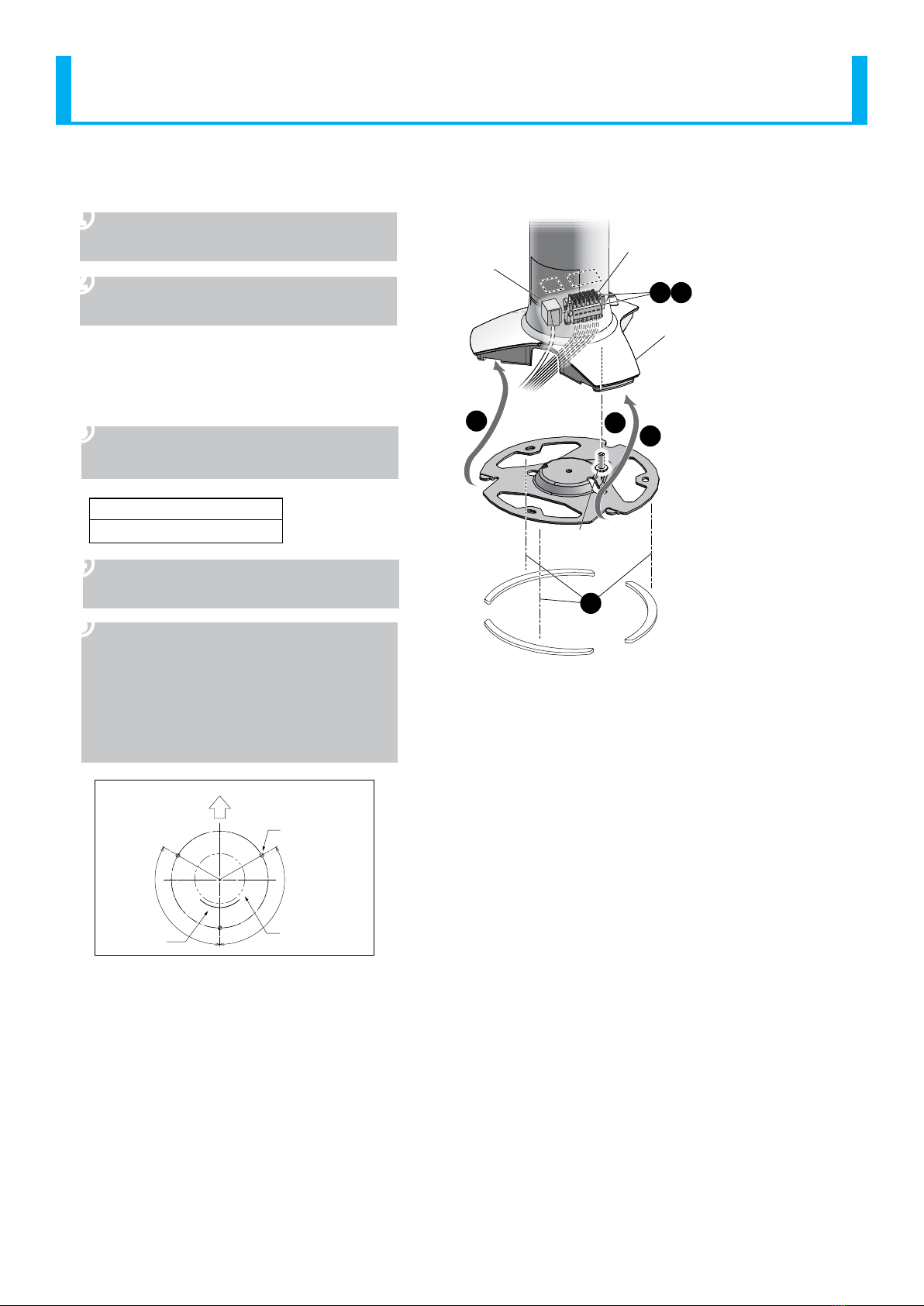
❶Make holes for the mount and wire
distribution hole for the product.
❷Firmly hold the LAN Unit, and the turn
to the left to remove it.
❸Secure the LAN bracket with the
accessorized nuts.
Recommended Torque
0.75N/m (Standard)
❹It allows the LAN cable wiring to pass
through the distribution hole.
❺The lock on the terminal block
connector can be unlocked and
removed for wiring.
(Refer to“3.3.3. Terminal block
connector detachment method”)
(Refer to“3.4. Wiring”)
❻The LAN unit is connected to the
terminal block connector and LAN
cable.
❼The LAN unit is attached.
❽Sealing around the mounting holes
and the distribution hole is done if
necessary.
The gure shows the most common installation circumstances,
but cannot show for every possible circumstance.
Terminal Block Connector LAN Cable
LAN Unit
LAN
Bracket
※Mounting Board
Thickness 4mm or less.
2
5
7
6
4
8
1
3
Mounting Dimensional Drawing■
Mounting Hole
(φ5×3 places)
φ40
120°
Nameplate
Location
Product Front
(Buzzer Diaphram)
Product
Outside
Dimension Distribution Hole
(φ26)
120°
(Unit: mm)
10
Signal Tower LA6-POE Operation Manual
3.1.2. Stationary Type
❶Loosen the screw to remove the bottom
plate. (Do not completely remove the screw.)
❷The lock on the terminal block connector
can be unlocked and removed for wiring.
(Refer to 3.1.3. Terminal block
connector (Detachment
Method))(Refer to 3.2. Wiring)
❸The LAN unit is connected to the terminal
block connector and LAN cable.
Recommended Torque
0.6N/m (Standard)
❹The tab on the bottom of the stand cover is
hooked in place and secured with a screw.
❺Apply the rubber sheet onto the bottom
plate. The rubber sheet is peeled from the
yellow releasing paper, and is to be stuck
onto the bottom plate.
The transparent protection sheet on
the rubber sheet is to be removed after
attachment.
Stand Cover
Bottom
Plate Screw
Tab
Tab
Rubber
Sheet
Terminal Block Connector
Wiring
Through-hole
LAN Cable
LAN Unit
44
1
3
2
5
Mounting Dimensional Drawing■
(Unit:mm)
Mounting Hole
(φ5x3 places)
Product Front
(Buzzer Diaphram)
φ116
120°
120°
Nameplate
Location
LAN Unit Outer
Dimensions
The figure shows the most common installation
circumstances, but cannot show for every possible
circumstance.
11
Signal Tower LA6-POE Operation Manual
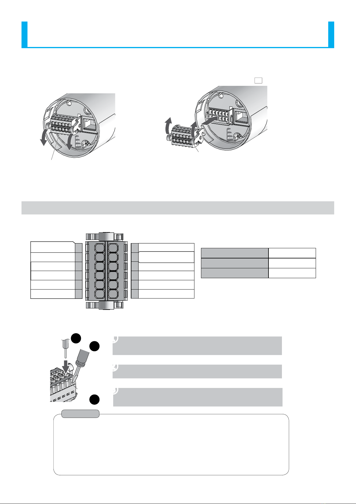
3.1.3. Terminal block connector (Detachment Method)
<Removing> <Attaching> ※The example figure shows the TN model.
Terminal block connector
〈Figure of LAN unit from the underside〉
Raise the lever
Referring to the drawing, depress the lever
on the right and left of the terminal block
connector to unlock it, and pull the terminal
block connector straight out.
Push the terminal block connector into the LAN unit until the levers
can be locked in place.
(When pushing the terminal block connector in place, the lever will
temporarily move up, before it moves down and locks into place.)
3.2. Wiring
3.2.1. Terminal Block Connector Pin Arrangement
■Recommended lead wire specifications
UL1007/UL1430
Wire Type
0.2-1.5mm2
Wire Gauge (Solid Wire)
AWG24-16
Wire Gauge (Frayed Wire)
7
8
9
10
11
12
1
2
3
4
5
6
Temperature rating should be above 75oC, and
the conductor material should be of copper wire.
COM
Flashing/Pulse Enable
Common
Mode Change
Input 7
Input 5
Power Wire
(Signal Wire Side)
Power Wire
Input 4
Input 3
Input 2
Input 1
Input 6
3.2.2. Wiring the Terminal Block
Slot
21
3
❶A minus driver etc. is placed on the slot and pushed into
the slot of the terminal block connector. (at a slight angle)
❷The stripped side of the lead wire is inserted in the slot.
❸The driver is then extracted from the slot. (Check to make
sure the lead wire has been locked in place.)
Point
The minus driver blade should be no less than 2.5mm in width and 0.4mm in
thickness. Any object that ts the dimensions is also ok.
Do not forcibly push the slot more than necessary with the driver. Failure to comply
may damage the unit.
Strip 6-7mm of wire insulation from the wire before inserting it in the Terminal Block.
When removing the lead wire, Do not just pull to remove.
(Be sure to slide the minus driver etc. into the slot to unlock it.)

12
Signal Tower LA6-POE Operation Manual
3.2.3. Wiring Example
The following is a basic wiring example.
If there are any special applications that require asking questions concerning this product, feel free to contact your PATLITE
Sales Representative.
* When lighting and ashing are used together in the Signal Tower mode with a PLC, it is necessary to separate the
ashing and non-ashing circuit outputs on the PLC side.
①
Wiring Example Index
LED Tier 1 / Input 1
Pin No.
(Refer to 3.2.1 Terminal Connector Pin Layout)
Function Name
[Signal Tower] mode/
[Smart Mode]
3.2.3.1. Connecting to Contact Relays with DC24V Input
LED Tier 1 / Input 1
LED Tier 2 / Input 2
LED Tier 3 / Input 3
LED Tier 4 / Input 4
LED Tier 5 / Input 5
Power Supply Wire
Flashing/Pulse Enable
Common line
Alarm 1 / Input 6
Mode Change
Common line
Power Supply Wire
Alarm 2 / Input 7
24V DC
(Class 2)(No polarity)
External
Contact 2
For Flashing /
Pulse Enable
External
Contact 1
For Lighting
Voltage Contact Relay
Power
24VDC Input
Do Not Apply Voltage!
⑧
⑩
⑥
⑤
①
⑪
②
⑦
④
③
⑫
⑨
LA6-POE
Do Not Use!
13
Signal Tower LA6-POE Operation Manual
3.2.3.2. Connecting to a PLC (NPN Type Transistor) with DC24V Input
PLC
E
CB
Circuit Schematic
External Contact Classication
PLC (NPN Transistor)
24V DC
(Class 2)
LED Tier 1 / Input 1
LED Tier 2 / Input 2
LED Tier 3 / Input 3
LED Tier 4 / Input 4
LED Tier 5 / Input 5
Power Supply Wire
Flashing/Pulse Enable
Common line
Alarm 1 / Input 6
Mode Change
Power Supply Wire
Alarm 2 / Input 7
Output Unit 2
For Flashing/
Pulse Enable
Output Unit 1
For Lighting
Power
24VDC Input
COM
LA6-POE
⑧
⑩
⑥
⑤
①
⑪
②
⑦
④
③
⑨
⑫
Do Not Apply Voltage!
Do Not Use!
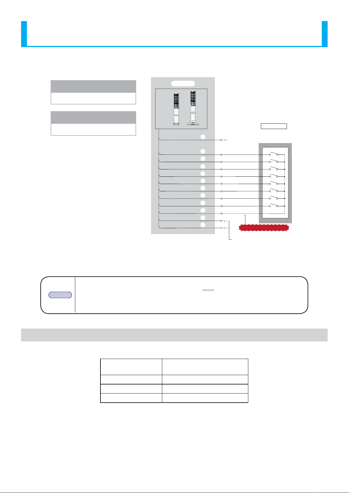
3.2.3.3. Connecting to a PLC (PNP Type Transistor) with DC24V Input
PLC
〈Note〉Since ashing and intermittence are
uncontrollable with the PNP type
transistor, do not connect it.
Control ashing and intermittence
with the PLC programming.
24V DC
(Class2)
LED Tier 1 / Input 1
LED Tier 2 / Input 2
LED Tier 3 / Input 3
LED Tier 4 / Input 4
LED Tier 5 / Input 5
Power Supply Wire
Flashing/Pulse Enable
Common line
Alarm 1 / Input 6
Mode Change
Power Supply Wire
Alarm 2 / Input 7
Do Not Apply Voltage!
Circuit Schematic
E
CB
COM
LA6-POE
Do Not Use!
External Contact Classication
PLC (PNP Transistor)
Power
24VDC Input
⑧
⑩
⑥
⑤
①
⑪
②
⑦
④
③
⑨
⑫
14
Signal Tower LA6-POE Operation Manual
3.2.3.4. Connecting to Contact Relay with PoE Input
LED Tier 1 / Input 1
LED Tier 2 / Input 2
LED Tier 3 / Input 3
LED Tier 4 / Input 4
LED Tier 5 / Input 5
Power Supply Wire
Flashing/Pulse Enable
Common line
Alarm 1 / Input 6
Mode Change
Common line
Power Supply Wire
Alarm 2 / Input 7
External
Contact 1
For Lighting
External Contact Classication
Voltage Contact Relay
Power
PoE Input
⑧
⑩
⑥
⑤
①
⑪
②
⑦
④
③
⑫
⑨
LA6-POE 〈Note〉Since ashing and Pulse
Enable Common are
uncontrollable for a PoE
input, do not connect it.
Do Not Use!
Do Not Use!
Do Not Apply Voltage!
3.2.4. LAN Cable Connection
The LAN cable should be rated for category 5e or higher. A straight or cross cable can be used.
MEMO
• Be sure to use the IEEE802.3af compliant products for the PoE power feeder systems.
• Priority is given to the DC24V power source when both the DC24V power source and
PoE power feeder systems are connected simultaneously.
• If both power sources are simultaneously connected, when disconnecting the DC24V
source, this product may reboot.
3.3. Contact Capacity
Signal Wire Contact Capacity
Current Capacity No more than 500 mA (DC24V)
No more than 100 mA (PoE)
Withstand Voltage DC 35V or greater
Leakage Current 0.1 mA or less
ON voltage (Vsat) Less than 1V
* Inrush current does not ow into the Mode Change line.

15
Signal Tower LA6-POE Operation Manual
4. How to Operate
4.1. Operating Procedure
4.1.1. Controlling with Commands
Set up the LA6-POE network.
• Set the IP address for the network. (Refer to“4.3 Network Setup”on page 19)
Set up the LED unit colors and combinations.
• Use the data setup application to create the LED unit colors and combinations.
(Refer to the help section in the data setup application.)
• Use the Web Setup Screen to set up. (Refer to“4.4.2 WEB Setup”on page 22)
Load the Setup Data information into the LA6-POE.
• Use the Web Setup Screen to load the data. (Refer to“4.4.1 Loading Setup Data” on page 20)
Set up the control method.
• Use a command control system in the Main Unit to set up with. (Refer to “4.5 Main Unit Setup”on page 24)
Set up the receiving command protocols.
• When controlled by PNS or PHN Commands:
Set up for receiving commands. (Refer to“4.6 Command Conguration” on page 25)
• When being controlled by Modbus/TCP:
Set up for Modbus/TCP commands. (Refer to “4.7 Modbus/TCP Setup”on page 26)
• When controlling with HTTP command, no conguration is required.
Set up the contact inputs.
• Set up the operation sequence for when an input occurs at the contact input.
(Refer to“4.8 Contact Input Detection”on page 27)
* The contact inputs are: clear/mute/trigger/STOP
4.1.2. When Controlling with the Signal Line Inputs
Set up the LA6-POE network.
• Set the IP address for the network. (Refer to“4.3 Network Setup”on page 19)
Set up the LED unit colors and combinations.
• Use the data setup application to create the LED unit colors and combinations.
(Refer to the help section in the data setup application.)
• Use the Web Setup Screen to set up. (Refer to“4.4.2 WEB Setup”on page 22)
Load the Setup Data information into the LA6-POE.
• Use the Web Setup Screen to load the data. (Refer to“4.4.1 Loading Setup Data” on page 20)
Set up the control method.
• Use a command control system to set up with the signal lines. (Refer to“4.5 Main Unit Setup”on page 24)
Set up the receiving command protocols.
• When acquiring status conditions by PNS or PHN Commands:
Set up for receiving commands. (Refer to“4.6 Command Conguration” on page 25)
• When acquiring status conditions by Modbus/TCP:
Set up for Modbus/TCP commands. (Refer to “4.7 Modbus/TCP Setup”on page 26)

16
Signal Tower LA6-POE Operation Manual
4.1.3. When Mirroring
Set up the LA6-POE network.
• Set the IP address for the network. (Refer to“4.3 Network Setup”on page 19)
Set up the LED unit colors and combinations.
• Use the data setup application to create the LED unit colors and combinations.
(Refer to the help section in the data setup application.)
• Use the Web Setup Screen to set up. (Refer to "4.4.2 WEB Setup" on page 22)
Load the Setup Data information into the LA6-POE.
• Use the data setup application to load the data. (Refer to "4.4.1 Loading Setup Data" on page 20R)
* Be sure to write the same information for the mirroring point and mirroring origin.
Mirroring Setup
• Setup mirroring for the point of origin, establishing the "Master."
(Refer to "4.9.1 Setting up the Mirroring Source" on page 29)
• Setup mirroring for the target point, establishing the "Slave."
(Refer to "4.9.2 Setup Mirroring Destination Point" on page 30)
4.1.4. When Collecting the Signal Tower Information
[ Retrieving the Signal tower information submitted by a LA6-POE ]
Set up the LA6-POE network.
• Set the IP address for the network. (Refer to“4.3 Network Setup”on page 19)
Set up the LED unit colors and combinations.
• Use the data setup application to create the LED unit colors and combinations.
(Refer to the help section in the data setup application.)
• Use the Web Setup Screen to set up. (Refer to "4.4.2 WEB Setup" on page 22)
Load the Setup Data information into the LA6-POE.
• Use the Web Setup Screen to load the data. (Refer to "4.4.1 Loading Setup Data" on page 20R)
* When writing data using the USB cable,be sure to synchronize the data in the "Main unit setup" screen.
Set up the control method.
• In the "Main Unit Setup" screen, set to the ”Signal Wire control.” (Refer to "4.5 Main Unit Setup" on
page 24)
Set up the Signal Tower Information Transmission.
• Set the receiver address. (Refer to "4.10 Information Transmission Setup" on page 31)
• Congure the Signal Tower Input Judgment. (Refer to "4.10 Information Transmission Setup" on page 31)
• Select the smart mode information to send. (Refer to "4.10 Information Transmission Setup" on page 31)

17
Signal Tower LA6-POE Operation Manual
[ Send a command to LA6-POE and collect information ]
Set up the LA6-POE network.
• Set the IP address for the network. (Refer to“4.3 Network Setup”on page 19)
Set up the LED unit colors and combinations.
• Use the data setup application to create the LED unit colors and combinations.
(Refer to the help section in the data setup application.)
• Use the Web Setup Screen to set up. (Refer to "4.4.2 WEB Setup" on page 22)
Load the Setup Data information into the LA6-POE.
• Use the Web Setup Screen to load the data. (Refer to "4.4.1 Loading Setup Data" on page 20)
* When loading data using the USB cable,be sure to synchronize the data in the "Main unit setup" screen.
Set up the control method.
• In the "Main Unit Setup" screen, set to the ”Signal Wire control.” (Refer to "4.5 Main Unit Setup" on page 24)
Command receiving setup.
• Set up for receiveing commands. (Refer to "4.6 Command Conguration" on page 25)
Set up the Signal Tower Information Transmission.
• Congure the Signal Tower Input Judgment. (Refer to "4.10 Information Transmission Setup" on page 31)
18
Signal Tower LA6-POE Operation Manual
4.2. Web Setup Screen
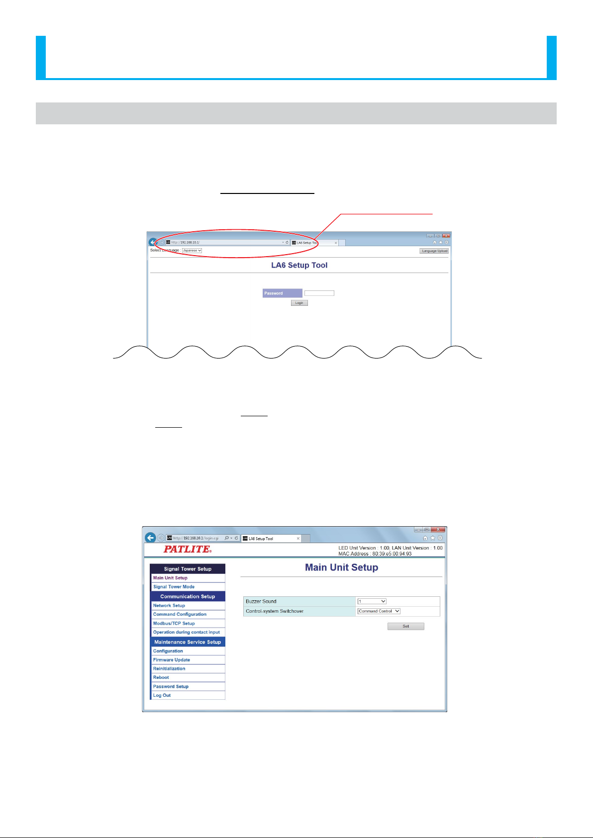
4.2.1. Login
Once the power supply is switched on and startup is complete, enter the IP address of this product into the web browser
address section.
The default IP address for this product is "192.168.10.1".
http://192.168.10.1
<Web Browser Input>
Login Screen
Recommended Browsers: Internet Explorer 11, Google Chrome
When the login screen is displayed, enter "patlite" in the password eld, then click the "Login" button.
The default password is "patlite", all in lower case letters. Be sure to change the password to prevent any security
breaching.
Be sure to change the network setup of the personal computer for the application as follows before communicating via a
browser.
The personal computer IP address: 192.168.10.2-254
Subnet Mask: 255.255.255.0
(The default IP address at the time of factory shipment)
After Login

19
Signal Tower LA6-POE Operation Manual
4.3. Network Setup
The network parameters for this product can be setup through a browser. The default IP address is "192.168.10.1". The items
that can be set up through the System Setup Screen is as follows for "Network Setup."
If "Setup Automatically" is selected, this product can accesses a DHCP server to acquire network information.
Network Setup
Item Contents Default Value Input Parameter
Setup Option
IP Address
Conguration Method
The method for setting up the IP address to this
product as manual or automatic is selected. Setup Manually * ×
IP Address Enter the IP address of this product. 192.168.10.1 IP Address Format ×
Subnet Mask Enter the subnet mask of this product. 255.255.255.0 IP Address Format ×
Default Gateway Enter the default gateway of this product. 0.0.0.0 IP Address Format ×
* The "Setup Option" indication is explained below to indicate in the diagram whether a value input is omissible (a blank is
used) or not.
The "O" indicates where it is omissible.
The "x" indicates where is not omissible, or is selected from an item menu.
!CAUTION
Even when the network Setup is changed to "Setup Automatically", if the DHCP server cannot be able to be accessed,
the network settings will not be changed.
If the DHCP server is not able to be accessed at the time of startup, the network settings start with the default values.

20
Signal Tower LA6-POE Operation Manual
4.4. LED Unit Setup
This product can control the Signal Tower in two modes, Signal Tower mode and smart mode.
Signal Tower Mode
It is a mode to set the tone color of each LED tier and buzzer in advance for this product and control it by the signal line
and commands.
Smart Mode
There are three types for the Smart Mode, "Time Trigger Type", "Pulse Trigger Type", and "Single Display Type":
• Time Trigger Type
The pattern transitions can be controlled in accordance to time.
• Pulse Trigger Type
The pattern transitions can be controlled in accordance to the trigger input.
• Single Display Type
The registered pattern is executed.
In each mode, every motion pattern is set in advance for this product and the pattern is executed in accordance to the
signal line and command settings.
There are two ways to set up this product, writing and loading data that was set up, or using Web settings.
4.4.1. Loading Setup Data
The LED unit can be Setup from the“EDITOR for LA series”. The set data can be written from the "Conguration" screen.
* For the Setup method, refer to the help section in the “EDITOR for LA series”.
[Data writing method in Web Setting]
In "Write LED Unit Setup Data", the data is selected in the“EDITOR for LA series”.
The "Write" button is clicked to update the LED unit Settings. It reboots automatically after updating.
Table of contents
Popular Desktop manuals by other brands


Dell
Dell OptiPlex 390 Technical guidebook

Lenovo
Lenovo ThinkCentre M71e user guide

New Star Computer Products
New Star Computer Products FPMA-MOBILE1800 instruction manual

Compaq
Compaq Evo W6000 Hardware reference guide

Lenovo
Lenovo ThinkCentre Edge 71 Používateľská príručka

HP
HP d330 - Desktop PC Updates to the Documentation