Patriot PE2 User manual

WWW.PATRIOTGLOBAL.COM
ELECTRIC FENCE USER
ENERGIZER MANUAL
PE2, PE5, PE10
PE5B, PE10B
WARNING: READ ALL INSTRUCTIONS
If you suspect that the unit is not
working, follow these steps:
1. Disconnect the unit from the
fence.
2. Check that the indicator light is
flashing.
3. Check that the voltage between the
fence and ground terminals is greater
than 4000 V, using a Patriot Digital
Voltmeter or Fence Tester.
4. If these tests are OK, you have an
installation problem.
STOP!
BEFORE
RETURNING THIS
PRODUCT TO
THE STORE…
Consult your user manual for installation and operating
instructions or contact Tru-Test Group Customer Service
on 800-874-8494.

2
Patriot PE2, PE5, PE10, PE5B, PE10B
Key to symbols on the unit
Fence ground terminal (green). Connect the fence ground terminal to
the ground system.
Fence output terminal (red). Connect the fence output terminal to the
fence.
Unit is suitable for connection to AC 120 V.
Unit is suitable for connection to DC 6 V/12 V.
Risk of electric shock! Do NOT open!
Read full instructions before use.
Double insulation – no serviceable parts.
Do not connect to mains-operated equipment such as battery chargers.

3
Instructions for PE2, PE5 and PE10
Installation - Indoors/dry locations with AC 120 V line connection
1 Mount the unit on a suitable vertical support or wall material using a 3”
(75 mm) flat headed nail. Hammer in the nail, allowing it to protrude by
3/8” (10 mm). Slide the unit onto the nail with the nail inside the mounting
hole on the back of the unit.
2 Connect the Fence ground terminal (green) to a separate ground system that
is at least 33’ (10 m) away from other ground systems.
3 Connect the Fence output terminal (red) to the fence.
Note:
If the unit is being mounted on a wall made of concrete, brick, plasterboard
or similar, use a screw instead of a nail. A wall anchor or plug may also be
required.
Operation
1 Plug the unit into the AC 120 V power supply.
2 Turn on the AC 120 V power supply switch.
The pulse indicator light flashes each time the unit pulses.
The linked image canno t be displayed. T he file may have been moved, renamed, or deleted. Ver ify that the link p oints to the correct
file and location.

4
Instructions for PE5B and PE10B
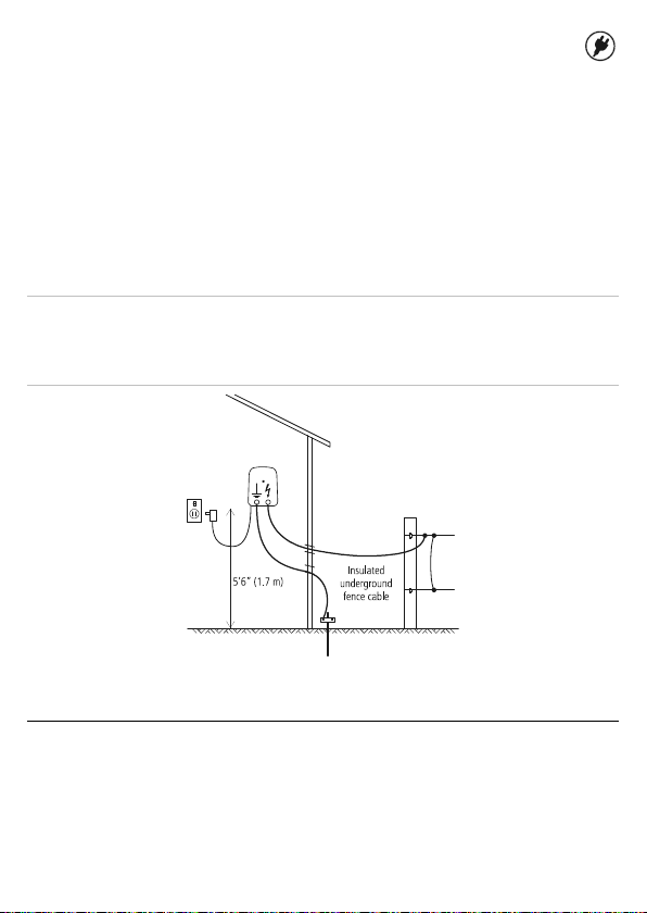
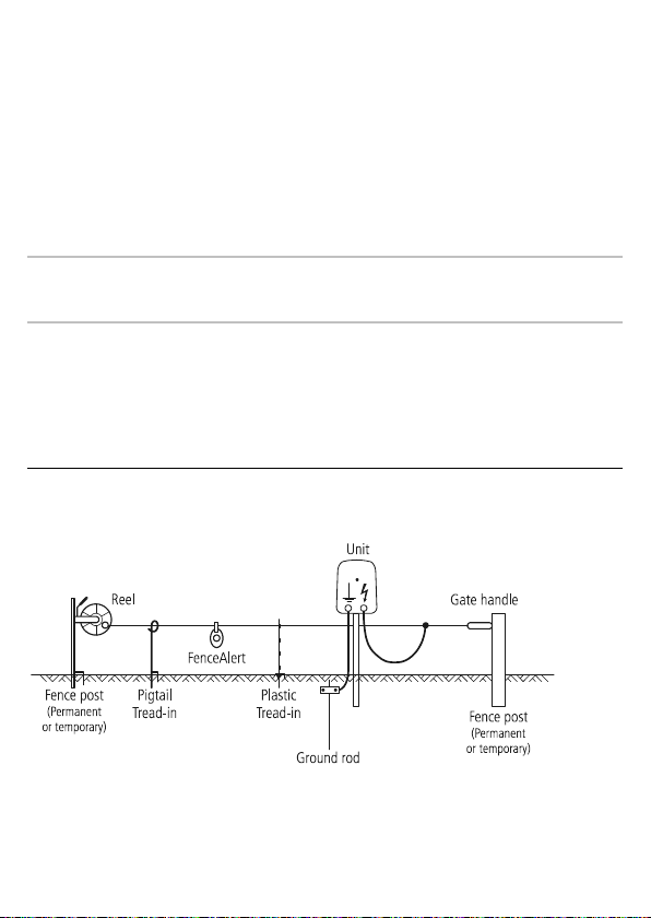
Installation and operation - DC 6 V/12 V battery connection
1 The unit can be mounted directly onto a steel T-post or Y-post using the
mounting slot in the case rear. Alternatively, the unit can be mounted onto a
wooden post, another suitable vertical support or suitable wall material
using a 3” (75 mm) flat headed nail. Hammer in the nail, allowing it to
protrude by 3/8” (10 mm). Slide the unit onto the nail with the nail inside
the mounting hole on the back of the unit.
2 Connect the Fence ground terminal (green) to a separate ground system that
is at least 33’ (10 m) away from other ground systems.
3 Connect the Fence output terminal (red) to the fence.
4 Connect the unit to a 6 V/12 V battery using the battery leads. Attach the +
(red) clip to the positive terminal of the battery, and the – (black) clip to its
negative terminal.
The pulse indicator light
flashes each time the unit
pulses.
5 To prevent damage caused
by stock interference and
bad weather, house the
battery and the unit in
protective enclosures.
Note:
If the unit is being mounted on a wall made of concrete, brick, plasterboard
or similar, use a screw instead of a nail. A wall anchor or plug may also be
required.
Caution!
When connecting the battery, be careful not to short-circuit the
supply terminals.
The linked image canno t be displayed. T he file may have been moved, renamed, or deleted. Ver ify that the link p oints to the correct
file and location.

5
Battery information
Use a 6 V/12 V rechargeable lead-acid battery.
Do not dispose of the battery in a land-fill or in a fire.
In the event of a spill or leakage from a lead-acid battery:
• Contain small spills with dry sand, earth and vermiculite. Do not use
combustible materials. If possible, carefully neutralise spilled acid with soda
ash, sodium bicarbonate, lime, etc.
• Wear acid-resistant clothing, boots, gloves and a face shield.
• Do not let acid get into the sewerage system.
• Neutralised acid must be managed in accordance with approved local, state
and federal requirements. Consult your state environmental agency and/or
federal EPA.
Battery charging
Warning!
- Do not attempt to recharge a non-rechargeable battery.
- When recharging a battery, ensure that there is adequate ventilation to
allow gases to disperse.
- The battery must be disconnected from the unit before connecting it to a
battery charger.
Regular recharging of the battery is essential. Use a suitably rated battery charger
and refer to the battery manufacturer’s recommendations.
Building an electric fence
Note:
This product has been designed for use with electric animal fences.
For information about building an electric fence, refer to the Patriot website
www.patriotglobal.com.

6
Grounding a fence
All-live fence - For most soil types
The animal receives a shock when it completes a circuit between the fence and
the ground system. The fence above has all live wires and requires conductive
soils.
Ground wire return fence - For dry, sandy or frozen ground conditions, where soil
conductivity is low.
The animal receives a shock when it completes a circuit between a live wire and a
ground wire. The fence above has both live wires and ground wires (not insulated
to the post). The ground wire is connected back to the grounding system.

7
Installing a ground system
Select a suitable site for the ground system. The site needs to be:
• At least 33’ (10 m) from other ground systems (e.g. telephone, AC 120 V
power or the ground system of another unit).
• Away from stock or other traffic that could interfere with the installation.
• At a site that can be easily observed for maintenance.
• Ideally at a site that has damp soil (e.g. a shaded or swampy location).
Note:
The site for the ground system does not need to be directly adjacent to
where the unit is installed.
Drive a single ground rod into the soil. Use insulated cable to connect the ground
rod to the unit’s Fence ground terminal. Ensure that there is a good electrical
connection at both ends.
Temporary fence construction for DC units only
Temporary fence components

8
Recommended wire spacing
Dairy cattle
Sheep
Cattle

9
Safety considerations
Warning!
- PE5B and PE10B only - Do not connect to AC 120 V operated equipment.
- PE2, PE5 and PE10 only - To reduce the risk of electric shock, the unit has a
polarized plug (one blade is wider than the other). This plug will fit in a
polarized outlet one way. If the plug does not fit fully in the outlet, reverse
the plug. If it still does not fit, contact a qualified electrician to install the
proper outlet. Do not change the plug in any way.
- Disconnect the unit from the supply before installation or performing any
work on the fence.
- Read all the safety considerations carefully.
- Check your installation to ensure that it complies with all local safety
regulations.
- Do not connect simultaneously to a fence and to any other device such as a
cattle trainer or a poultry trainer. Otherwise, lightning striking your fence will
be conducted to all other devices.
Notes:
- This product has been designed for use with electric animal fences.
- Keep these instructions in a handy location.

10
Safe electric fence construction
Warning!
Read before use.
An electric fence can be hazardous when there is a risk of entrapment or
entanglement, or other hazards exist. Serious injury or death may result. Take all
steps to avoid the risk of entrapment or entanglement.
Hazards
Do not climb through or under an electric fence. If it is necessary to cross an
electric fence use a gate or specially designed crossing point.
Do not allow young or infirm persons to use this unit without supervision. Do
not allow young children to play with this unit or near an electric fence or
electrified wires.
Do not electrify barbed wire.
Do not support off-set electrified wires less than 6” (150 mm) from the
vertical plane of a barbed wire fence.
Do not electrify any fence construction which could lead to entanglement of
persons or animals. We recommend for instance, that no more than one
electrified off-set wire be supported on either side of a barbed wire or mesh
fence.
Do not supply an electric fence from two units.
Do not allow electrified wires from two units on the same or adjacent
properties to be less than 8’ (2.5 m) apart.
Do not place the unit’s ground electrode within 33’ (10 m) of any part of a
power supply ground system or telecommunications ground system.
Do not run electric fence wires above or close to overhead power or
communication lines.

11
Duty to the public
A warning sign shall be fitted to every point where persons may gain ready access
to the conductors.
Where an electric animal fence crosses a public pathway, a non-electrified gate
shall be incorporated in the electric animal fence at that point or a crossing by
means of stiles shall be provided. At any such crossing, the adjacent electrified
wires shall carry warning signs.
Any part of an electric animal fence that is installed along a public road or
pathway shall be identified at frequent intervals by warning signs securely
fastened to the fence posts or firmly clamped to the fence wires.
• The size of the warning sign shall be at least 4x8” (100x200 mm).
• The background colour of both sides of the warning sign shall be yellow.
The inscription on the sign shall be black and shall be either:
or the substance of “CAUTION: Electric fence”.
• The inscription shall be indelible, inscribed on both sides of the warning sign
and have a height of at least 1” (25 mm).

12
Definition of special terms
Unit/Charger/Energizer
– An appliance that is intended to periodically deliver
voltage impulses to a fence connected to it.
Fence
– A barrier for animals or for the purpose of security, comprising one or
more conductors such as metal wires, rods or rails.
Electric fence
– A barrier which includes one or more electric conductors,
insulated from ground, to which electric pulses are applied by a unit.
Ground electrode
– Metal structure that is driven into the soil near a unit and
connected electrically to the Fence ground terminal of the unit, and that is
independent of other grounding arrangements.
Connecting lead
– An electric conductor, used to connect the unit to the electric
fence or the ground electrode.
Requirements for electric animal fences
Electric animal fences and their ancillary equipment shall be installed, operated
and maintained in a manner that minimises danger to persons, animals or their
surroundings.
Warning!
Avoid contacting electric fence wires especially with the head, neck
or torso. Do not climb over, through or under a multi-wire electric fence. Use a
gate or a specially designed crossing point.
This unit is not intended for use by persons (including children) with reduced
physical, sensory or mental capabilities, or lack of experience and knowledge,
unless they have been given supervision or instruction concerning use of the unit
by a person responsible for their safety.
Children should be supervised to ensure that they do not play with the unit.
Electric animal fence constructions that are likely to lead to the entanglement of
animals or persons shall be avoided.
An electric animal fence shall not be supplied from two separate units or from
independent fence circuits of the same unit.

13
For any two separate electric animal fences, each supplied from a separate unit
independently timed, the distance between the wires of the two electric animal
fences shall be at least 8’ (2.5 m). If this gap is to be closed, this shall be effected
by means of electrically non-conductive material or an isolated metal barrier.
Barbed wire or razor wire shall not be electrified by a unit.
A non-electrified fence incorporating barbed wire or razor wire may be used to
support one or more off-set electrified wires of an electric animal fence. The
supporting devices for the electrified wires shall be constructed so as to ensure
that these wires are positioned at a minimum distance of 6” (150 mm) from the
vertical plane of the non-electrified wires. The barbed wire and razor wire shall be
grounded at regular intervals.
Go to www.patriotglobal.com for information about grounding.
A distance of at least 33’ (10 m) shall be maintained between the unit’s ground
electrode and any other grounding system connected parts such as the grounding
system for the power supply or the telecommunication system.
Connecting leads that are run inside buildings shall be effectively insulated from
the grounded structural parts of the building. This may be achieved by using
insulated high voltage cable.
Connecting leads that are run underground shall be run in conduit of insulating
material or else insulated high voltage cable shall be used. Care must be taken to
avoid damage to the connecting leads due to the effects of animal hooves or
vehicle wheels sinking into the ground.
Connecting leads shall not be installed in the same conduit as the AC supply
wiring, communication cables or data cables.
Connecting leads and electric animal fence wires shall not cross above overhead
power or communication lines.
Crossings with overhead power lines shall be avoided wherever possible. If such a
crossing cannot be avoided it shall be made underneath the power line and as
nearly as possible at right angles to it.
If connecting leads and electric animal fence wires are installed near an overhead
power line, the clearances shall not be less than those shown in the table below.

14
Minimum clearances from power lines for electric animal fences
Power line voltage Clearance
≤1000 V 10‘ (3 m)
>1000 V to ≤33,000 V 13’ (4 m)
>33,000 V 27’ (8 m)
If connecting leads and electric animal fence wires are installed near an overhead
power line, their height above the ground shall not exceed 10’ (3 m). This height
applies to either side of the orthogonal projection of the outermost conductors of
the power line on the ground surface, for a distance of:
• 6’6” (2 m) for power lines operating at a nominal voltage not exceeding
1000 V.
• 50’ (15 m) for power lines operating at a nominal voltage exceeding
1000 V.
Electric animal fences intended for deterring birds, household pet containment or
training animals such as cows need only be supplied from low output units to
obtain satisfactory and safe performance.
In electric animal fences intended for deterring birds from roosting on buildings,
no electric fence wire shall be connected to the unit’s ground electrode.
Ensure that all line-operated, ancillary equipment connected to the electric animal
fence circuit provides a degree of isolation between the fence circuit and the
supply mains equivalent to that provided by the unit.
Protection from the weather shall be provided for the ancillary equipment unless
this equipment is certified by the manufacturer as being suitable for use outdoors.
Servicing
This product is NOT serviceable. Please refer to the warranty conditions at
www.patriotglobal.com.

15
Consulte nuestra página web patriotglobal.com para acceder a las instrucciones completas
de instalación y funcionamiento.
Pour les instructions complètes d’installation et d’utilisation, veuillez vous reporter à notre
site web patriotglobal.com.
Explication des symboles sur l’électrificateur
Borne de terre de la clôture (vert). Connectez la borne de terre au
système de mise à la terre de l’électrificateur.
Borne de sortie vers la clôture (rouge). Connectez la borne de sortie à la
clôture.
Cet électrificateur est conçu pour être utilisé avec du courant alternatif
de 120 V.
Cet électrificateur est conçu pour être utilisé avec du courant continu de
6 V et 12 V.
Risque de choc électrique ! Ne pas ouvrir !
Lire attentivement toutes les instructions avant usage.
Double isolation : ne contient pas de pièces réparables.
Ne jamais raccorder cet appareil à des équipements alimentés par le
réseau électrique, tels que des chargeurs de batterie.

16
Attention !
- Ne jamais charger une batterie non rechargeable.
- Pendant le chargement de la batterie, assurer une ventilation adéquate pour
permettre aux gaz de se dissiper.
- La batterie doit être déconnectée de l’électrificateur avant sa connexion à un
chargeur.
Attention !
- PE5B et PE10B uniquement - Ne jamais raccorder cet appareil à des équipements
alimentés par le réseau électrique.
- PE2, PE5 et PE10 uniquement - Pour réduire le risque d’une secousse électrique,
l’unité a une fiche polarisée (une lame est plus large que l'autre). Cette fiche ne
rentre dans une prise polarisée que dans un sens. Si la fiche ne rentre pas
entièrement dans la prise, retournez la fiche. Si elle ne rentre toujours pas,
contactez un électricien qualifié pour installer la bonne prise. Ne modifiez pas la
fiche.
- Déconnectez l’unité du système d’alimentation électrique avant de procéder à
tout travail d’installation ou toute autre intervention sur la clôture.
- Lisez attentivement toutes les règles de sécurité.
- Vérifiez soigneusement que votre clôture est en conformité avec tous les
règlements locaux de sécurité.
- Ne raccordez jamais un électrificateur simultanément à une clôture et à un autre
appareil tel qu’un système de dressage de bétail ou de volaille. Sinon, la foudre
pouvant tomber sur votre clôture risque de s’étendre à tous les autres appareils.
Notes :
- Ce produit a été conçu pour une utilisation avec des clôtures électriques pour
animaux.
- Gardez ces instructions à un endroit pratique.

17
Installation d’une clôture électrique sûre
Attention !
Lisez avant utilisation.
Une clôture électrique peut être dangereuse si elle présente un risque
d’embrouillement ou d’emmêlement ou que d’autres risques existent. Des
blessures graves ou la mort peuvent en être la conséquence. Prenez les mesures
nécessaires pour éviter tout risque d’embrouillement ou d’emmêlement.
Dangers
Ne passez pas par-dessus ou par-dessous une clôture électrique. Si vous devez traverser une
clôture électrique, utilisez une porte ou un passage spécialement aménagé.
Ne permettez jamais aux enfants ou à des personnes ayant une quelconque infirmité d’utiliser cet
appareil sans supervision. Ne laissez jamais jouer un enfant avec cet appareil ou à proximité d’une
clôture électrique ou d’un fil électrifié.
N’électrifiez jamais des fils barbelés.
Ne jamais électrifier des fils montés en parallèle d’une clôture de fil de fer barbelé et se trouvant à
moins de 6” (150 mm).
N’électrifiez jamais une clôture qui pourrait entraîner un risque d’emmêlement pour l’homme ou les
animaux. Nous vous recommandons, par exemple, de n’installer qu’un seul fil décalé électrifié par
côté d’un fil barbelé ou d’un grillage.
N’alimentez jamais une clôture électrique par deux électrificateurs.
Assurez toujours une distance d’au moins 8’ (2,5 m) entre des fils électrifiés de deux appareils sur
le même lotissement ou un lotissement voisin.
Ne mettez jamais la prise de terre de l’électrificateur à moins de 33’ (10 m) de toute partie d’une
prise de terre d’un réseau électrique ou de lignes de télécommunication.
N’installez jamais des fils de clôture électrique au-dessus ou près de lignes électriques ou de
télécommunication aériennes.
Obligation envers le public
Une plaque de signalisation doit être mise en place partout où des personnes
auront accès aux conducteurs.

18
Partout où une clôture électrique pour animaux croise un chemin public, une porte
non électrifiée sera incorporée à la clôture électrique pour animaux ou bien un
passage au moyen d’une échelle sera prévu. Les fils électrifiés adjacents à ces
passages doivent être munis de plaques de signalisation.
Toute partie d’une clôture électrique pour animaux installée le long d’une voie
publique ou d’un sentier sera signalée à des intervalles fréquents par des plaques
de signalisation qui seront solidement attachées aux piquets ou accrochées à la
ligne de clôture.
• La taille des plaques de signalisation sera au moins de 4x8” (100x200 mm).
• La couleur de fond des plaques doit être jaune des deux côtés. L’inscription
sur la plaque doit être en noir et soit indiquer le symbole ci-dessous :
soit indiquer en substance « ATTENTION : Clôture électrique ».
• L’inscription doit être ineffaçable, inscrite sur les deux côtes de la plaque de
signalisation et avoir une hauteur minimale de 1” (25 mm).
Définitions des termes techniques
Électrificateur de clôture :
appareil émettant régulièrement des impulsions
électriques à la clôture connectée à l’électrificateur.
Clôture :
une barrière utilisée pour contenir des animaux ou pour des raisons de
sécurité qui comprend une ou plusieurs conducteurs tels fils métalliques, piquets
ou lattes.
Clôture électrique :
une barrière comprenant un ou plusieurs conducteurs
électriques, isolée de la terre et soumise à des impulsions électriques générées par
un électrificateur.
Prise de terre :
structure métallique enfoncée dans le sol à proximité d’un
électrificateur et connectée électriquement à la borne de terre de l’électrificateur,
structure séparée de tout autre système de mise à la terre.
Fil de connexion :
un conducteur électrique, utilisé pour relier l’électrificateur à la
clôture électrique ou à la prise de terre.

19
Warranty
This warranty does not cover defects caused by:
• Incorrect input voltage or polarity
• Damage to external wiring
• Physical mishandling
• Water immersion
• Vermin or insect damage
This warranty covers defects caused by lightning.
Note:
This product has been manufactured to comply with international safety standards.
This product is warranted against faulty material and workmanship for a period of 2 years FROM DATE
OF PURCHASE.
If a warranted defect occurs, return this product with proof of purchase to an authorised service centre.
For details, see www.patriotglobal.com
Note:
- No responsibility is accepted for any accident or damage caused subsequent to any tampering with
or modification to or misuse of this product, including (but not limited to) alterations made by
anyone other than Tru-Test Group or its agents.
- To the maximum extent permitted by law, this warranty is exclusive, personal to you and in lieu of
all other warranties, representations or conditions relating to this product (whether express or
implied and whenever arising) whether originating by statute, law, trade, custom or otherwise.
- The product warranty is only valid in the original country of purchase. Any claims made in another
country may incur full repair costs at the owner’s expense.

FOR USE WITH:
STEEL WIRE
ALUMINUM WIRE
POLIWIRE / POLIROPE
POLITAPE
SAVE THESE INSTRUCTIONS
RECOMMENDATIONS
MANUFACTURED IN
NEW ZEALAND
819866 ISSUE 5 06/2018
©2011-2018 TRU-TEST LIMITED
PE2PE5PE10 PE5B PE10B
This manual suits for next models
4
Table of contents
Other Patriot Power Supply manuals