TP-Link PSM150-AC User manual

REV2.0.0
710650
6700
Installation Guide
PSM150-AC
Business Networking Solution
150W AC Power Supply Module

Chapter 1 Introduction
1.1 Overview of the Product
The PSM150-AC is an AC-input and DC-output power supply
module. It can convert the input voltage to 12 Volts with the
maximum output power of 150 Watts. The power supply
module is fully hot swappable, helping to ensure no system
interruption during installation or replacement. PSM150-AC is
applicable to multiple TP-Link switch models.
Power
PS OK
Fault
PSM150-AC
100-240~50/60Hz 2.5A
Figure 1-1 Appearance of PSM150-AC
Power
PS OK
Fault
PSM150-AC
100-240~50/60Hz 2.5A
Fastening Screw AC power input jack
Power supply module handle
Figure 1-2 Front Panel of PSM150-AC
1

1.2 Description of LEDs
There are three LEDs on the front panel of PSM150-AC.
Described below:
LED Status
Description
Power On
Power supply module is powered on and running well, but not
supplying power to the switch.
PS OK Off
Fault Off
Power On
PS OK On
Power supply module is powered on and running well, and
supplying power to the switch.
Fault Off
Power On
Fault On
The circuit has faults, such as output over-
voltage, output
under-voltage, output over-current
, output short circuit,
hot-swap control failure (note 1) or fan fault.
PS OK Off
Power Off
PS OK Off
Fault Off
AC power off or power supply fault.
Table 1-1 LED Status
Note:
•Hot-swap control function will be checked when
PSM150-AC is powered on but has not been inserted into
the switch. If the Fault LED is on under this condition,
please do not insert PSM150-AC into the switch,
otherwise the power supply module or the powered
devices may be damaged.
•The failure of output over-voltage or over-current may
cause the power LED to flash.
2

1.3 Description of Features
Feature
Description
Protection function
Includes output over-voltage protection
, output
under-voltage protection, output short circuit protection
and output over-current protection.
Redundant backup
Supports dual power modules combining in parallel to
implement 1+1 redundancy for
uninterruptible power
supply.
Hot Swappable
In the case of 1+1 redundant power supply system, the
PSM150-AC can be plugged out or plugged in without
shutting down the switch.
Table 1-2 Features of PSM150-AC
When the power module reverts to the protected state, its
recovery characteristics are shown in Table 1-3.
Protection
function
Protective
action
Recovery characteristics
Output
over-voltage &
under-voltage
protection
Power supply module
locked and cut-off
supply
The power supply can not recover
automatically.
Output short
circuit
protection
Power supply module
locked and cut-off
supply
Power supply module reverts into the
auto-
retry mode. It can recover
automatically when the fault is cleared.
Output
over-current
protection
Power supply module
locked and cut-off
supply
Power supply module revert
s into the
auto-
retry mode. It can recover
automatically when the fault is cleared.
Table 1-3 Protection Functions of PSM150-AC
3

Note:
When the power supply module is locked or auto-retry
continually, you can try the following steps to restore the
device.
1. Disconnect the power cord from the external power
supply system.
2. Disconnect the power cord from the power supply
module.
3. Remove the power supply module from the switch.
4. Insert the power supply module again.
5. Connect the power cord to the power supply module
again.
6. Connect the other end of the power cord to the external
supply system.
Chapter 2 Installation
The process of installation and removal of the power supply
module is illustrated in Figure 2-1 and Figure 2-2.
Figure 2-1 The Installation Process
Figure 2-2 The Removal Process
4

Note:
For safety considerations, the above process are
recommended by TP-Link, however, PSM150-AC can also
support installation or removal when the AC power supply is
on.
2.1 Safety Information
To avoid damage to the power supply module and the
equipment and bodily injury, please observe the following
notes:
•When you install and remove the power supply module,
please wear an ESD-preventive wrist strap, and make sure
that it has good skin contact and is well grounded.
•Before installing the power supply module, make sure that
the voltage of external power supply system is the same
with the voltage marked in the power supply module, and
the output voltage of the power supply module is the
same with the required voltage of the powered devices in
order to prevent damaging the power supply module or
the powered devices.
•Do not touch any exposed wires or terminals to avoid
bodily injury.
•Do not place the power module in a humid place or let the
liquid into the power supply module.
•If there is a failure inside the module, please contact
service personnel, instead of opening the housing of the
module.
5

2.2 Tools for Installation
•Straight screwdriver
•Philips screwdriver
•ESD-preventive wrist strap
2.3 Installing & Removing the Power Supply Module
•Installing the Power Supply Module
1. Wear an ESD-preventive wrist strap, and make sure that it
has good skin contact and is well grounded.
2. Grip the handle of the module with one hand, and hold the
bottom of the module using your other hand. Gently push
the module in along the slot guide rail until the module is
flush with the switch, as shown in Figure 2-3.
Figure 2-3 Install Power Supply Module
3. Tighten the captive screws with a Phillips screwdriver to
fix the power supply module in place.
6

•Removing the Power Supply Module
1. Wear an ESD-preventive wrist strap, and make sure that it
has good skin contact and is well grounded.
2. Remove the power cord from the external power supply
system and the power module.
3. Use a Phillips screwdriver to loosen the captive screws at
both sides of the power supply module until all spring
pressure is released.
4. Pull the handle with one hand towards you along the guide
rails, and hold the bottom of the module using your other
hand, until it completely comes out of the switch chassis.
Note:
When installing or removing a power supply module, pay
attention to the following points:
•Make sure that the power supply module is set correctly
in the operation of installation.
•Do not use too much force in the installation. If resistance
is encountered or positions of the power supply module
appear larger during installation, you must first remove
the module and then reinstall the module.
•If screws can not be tighten, it may be due to the power
supply module is not installed properly. Please check
carefully.
7
•In order to better protect the power supply module during
removal, it is recommended that you package it in an
antistatic bag.
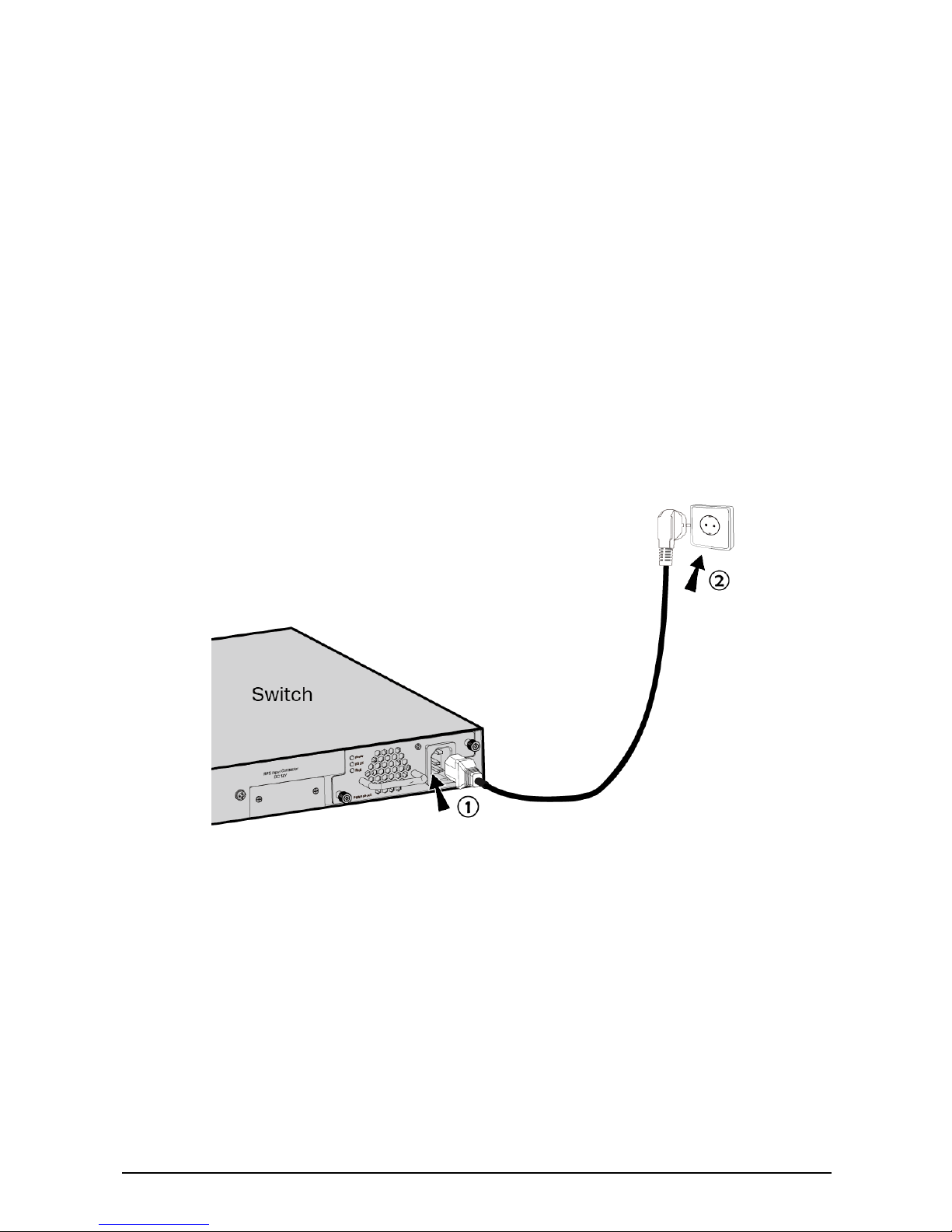
2.4 Connecting the Power Cord
•Connecting the Power Cord
After the power supply module is installed on the switch,
please plug the female connector of the provided power cord
into the power socket of the device, and the male connector
into a power outlet as the following figure shows.
Figure 2-4 Connect the Power Cord
2.5 Verifying the Installation
To verify the installation status of PSM150-AC, firstly, please
make sure the two captive screws on PSM150-AC are
tightened, then connect the power cord and check the LEDs
of PSM150-AC. If the Power LED is on while Fault LED is off, it
8

indicates that the AC power input is good and the device is
working properly, and the installation of PSM150-AC has been
successful.
9

Appendix: Specifications
Item
Specification
AC Power Input
100V-240V
~
50/60Hz
Output Voltage
12VDC
Output Current
12.5A (Maximum)
Output Power
150W (Maximum)
Temperature
Operation : 0
°
C to 40
°
C (32 to 104
°
F)
Storage: -40
°
C to 70
°
C (-40 to 158
°
F)
Humidity
Operation : 20% to 90% RH Non-condensing
Storage: 10% to 95% RH Non-condensing
10

FCC STATEMENT
This equipment has been tested and found to comply with the
limits for a Class A digital device, pursuant to part 15 of the
FCC Rules. These limits are designed to provide reasonable
protection against harmful interference when the equipment is
operated in a commercial environment. This equipment
generates, uses, and can radiate radio frequency energy and,
if not installed and used in accordance with the instruction
manual, may cause harmful interference to radio
communications. Operation of this equipment in a residential
area is likely to cause harmful interference in which case the
user will be required to correct the interference at his own
expense.
This device complies with part 15 of the FCC Rules. Operation
is subject to the following two conditions:
1) This device may not cause harmful interference.
2) This device must accept any interference received,
including interference that may cause undesired
operation.
Any changes or modifications not expressly approved by the
party responsible for compliance could void the user’s
authority to operate the equipment.
CE Mark Warning
This is a class A product. In a domestic environment, this

product may cause radio interference, in which case the user
may be required to take adequate measures.
Industry Canada Statement
CAN ICES-3 (A)/NMB-3(A)
Korea Warning Statements
당해 무선설비는 운용중 전파혼신 가능성이 있음.
BSMI Notice
安全諮詢及注意事項
請使用原裝電源供應器或只能按照本產品注明的電源類型使用本
產品。
清潔本產品之前請先拔掉電源線。請勿使用液體、噴霧清潔劑或
濕布進行清潔。
注意防潮,請勿將水或其他液體潑灑到本產品上。
插槽與開口供通風使用,以確保本產品的操作可靠並防止過熱,
請勿堵塞或覆蓋開口。
請勿將本產品置放於靠近熱源的地方。除非有正常的通風,否則
不可放在密閉位置中。
請不要私自打開機殼,不要嘗試自行維修本產品,請由授權的專
業人士進行此項工作。
此為甲類資訊技術設備,于居住環境中使用時,可能會造成射頻擾動,
在此種情況下,使用者會被要求採取某些適當的對策。

Продукт сертифіковано згідно с правилами системи
УкрСЕПРО на відповідність вимогам нормативних
документів та вимогам, що передбачені чинними
законодавчими актами України.
Safety Information
When product has power button, the power button is
one of the way to shut off the product; When there is no
power button, the only way to completely shut off power
is to disconnect the product or the power adapter from
the power source.
Don’t disassemble the product, or make repairs yourself.
You run the risk of electric shock and voiding the limited
warranty. If you need service, please contact us.
Avoid water and wet locations.
Explanation of the symbols on the product label
Symbol
Explanation
AC voltage
DC voltage

RECYCLING
This product bears the selective sorting symbol for Waste
electrical and electronic equipment (WEEE). This means
that this product must be handled pursuant to European
directive 2012/19/EU in order to be recycled or
dismantled to minimize its impact on the environment.
User has the choice to give his product to a competent
recycling organization or to the retailer when he buys a
new electrical or electronic equipment.
© 2016 TP-Link

Table of contents
Other TP-Link Power Supply manuals


Popular Power Supply manuals by other brands

Whelen Engineering Company
Whelen Engineering Company UPS188C installation guide

New Focus
New Focus 901 user guide

Allen-Bradley
Allen-Bradley 1606-XLB240E Reference manual

Horizont
Horizont hotshock N500 instruction manual

Rothenberger
Rothenberger 15812 Instructions for use

Carmanah
Carmanah SpeedCheck-15 Guide


