S1-5 and S1-6: Clock Source
Switches S1-5 and S1-6 are set in combination to determine the
transmit clock source for the Model 1140RC.
S1-5 S1-6 Setting
On On Internal transmit clock
Off On Receive recover clock
On Off External transmit clock
S1-7: Asynchronous/Synchronous Mode
The setting for switch S1-7 determines whether the Model 1140RC
is in asynchronous or synchronous operating mode.
S1-7 Setting
On Asynchronous
Off Synchronous
S1-8: Carrier Control Method
The setting for switch S1-8 determines whether the carrier is
“constantly on” or “controlled by RTS”. This setting allows for operation
in switched carrier, multipoint and/or hardware handshaking
applications.
S1-8 Setting
Off Constantly On
On Switched Carrier
615
5.3 TEST MODES
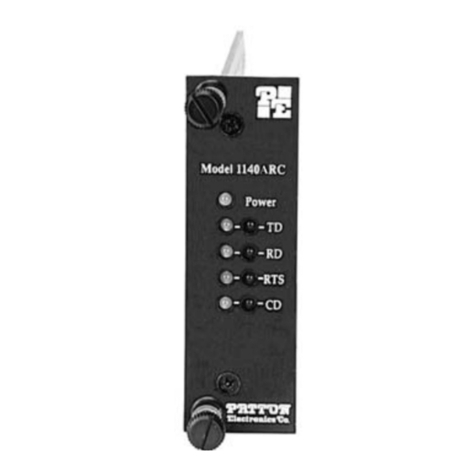
The Model 1140RC offers two V.54 test modes and two V.52 test
modes to evaluate the condition of the modems and the communication
link. Both sets of tests can be activated physically from the front panel.
The V.54 test can also be activated from the RS-232 interface.
Note:
V.54 and V.52 test modes on the Model 1140RC are available for point-
to-point applications only.
5.3.1 LOCAL ANALOG LOOPBACK (LAL)
The Local Analog Loopback (LAL) test checks the operation of the
local Model 1140RC, and is
performed separately on each unit.
Any
data sent to the local Model 1140RC in this test mode will be echoed
(returned) back to the user device. For example, characters typed on
the keyboard of a terminal will appear on the terminal screen. To
perform a LAL test, follow these steps:
1. Activate LAL. This may be done in one of two ways: First, by
moving the upper front panel toggle switch RIGHT to “Analog”.
Second, by raising pin 18 on the RS-232 interface (note: be
sure DIP switch S2-8 is off). Once LAL is activated, the Model
1140RC transmit output is connected to its own receiver. The
“Test” LED should be lit.
2. Verify that the data terminal equipment is operating properly
and can be used for a test.
3. Locate the lower of the two toggle switches on the front panel
of the Model 1140RC and move it to the right. This will
activate the V.52 BER test mode and inject a “511” test pattern
into the local loop. If any errors are present in the loop, the
red “Error” LED will blink sporadically.
4. If the BER test indicates
no errors
are present, move the V.52
toggle switch to the left, thus activating the “511/E” test with
periodic errors. If the test is working properly, the red “Error”
LED will light. A successful “511/E” test will confirm that the
loop is in place, and that the Model 1140RC’s built-in “511”
generator and detector are working properly.
5. If the BER test indicates that errors
are
present, check to see
that the RS-232 cable connecting the DTE to the Model
1140RC is wired straight through, and is plugged in properly.
Also, ensure that the Model 1140RC is configured properly.
Then re-check your DTE equipment. If you still have errors,
call Patton Technical Support at (301) 975-1007.
