Patz Corporation 400 Material Mover Instruction manual

Technical Data and Layout Planner
Patz Corporation
P.O. Box 7
Due to continual updating, design and specifications are Pound, WI 54161
subject to change without notice. Tel: (920) 897-2251
Fax: (920) 897-2142
PA-15589 Rev. 2/18 Copyright ©2001-2018 Patz Corporation PRINTED IN U.S.A. www.patzcorp.com
400 Material Mover
Chain Direction

2
Standard Equipment Specifications
Overall Lengths: 20’ (6.096 m) to 200’ (60.96 m). (Max. 400’ (152.4 m) chain length depending on load and configuration.)
Construction: All steel; slide is High-Strength, Corrosion Resistant steel.
Chain: 400 hook-and-eye, all steel link, progression forged; heat treated.
Flites: 467: 4” (102 mm) high at tip, 1/4” (6.4 mm) thick, all steel, 1/2” (12.7 mm) wear shoe welded to bottom.
447: 2” (51 mm) high, 1/4” (6.4 mm) thick, all steel, 2 x 3 x 1/2” wear shoe welded to bottom.
Steel Trough and Concrete Gutter width: 18” (457 mm).
Planetary Gear Drive: Planetary speed reducer with 12, 18, 24, 30 and 36 ft/min (3.7, 5.5, 7.3, 9.1 and 11 m/min) chain speed; 2, 3, 5 or
7-1/2 H.P. motor.
Heavy Roller Chain Drive: V-belt and single-strand final drive roller chain reducer with 18 or 30 ft/min (5.5 or 9.1 m/min) chain speed;
maximum 5 H.P. motor.
203SMTP Gearbox reducer drive: 24 or 36 ft/min (7.1 or 11 m/min) chain speed; 2 or 3 H.P. motor.
Load Capacity: Up to 45 ft3/min (1.274 m3/min), at 36 ft/min (11 m/min) depending on gutter width and depth, elevation and type of material
moved. (Through trapdoor, 25 ft3/min (0.708 m3/min))
Span: Up to 20’ (6.096 m) between supports.
Color: Blue baked-on-polyester powder coat and epoxy polyester finish.
Electrical Controls: Customer supplied.
Assembly: Conveyor supplied unassembled.
Options: Flite wiper brushes material off flites; stands for support; trapdoor to drop material out bottom of trough; covers for troughs; corner
sections; stainless steel slide; double corner wheels for smoother operation under heavier loads; steel liner for concrete trough provides
a smooth surface.
Drive Motors: 2, 3, 5 or 7-1/2 H.P., 1 ph. or 3 ph.
Optional Equipment Specifications
Calculating Capacity
Capacity and HP requirements can vary depending on the material moved, inclines involved and many other factors. Consideration must
be given to the machine layout, incline, elbows, chain length and speed, as well as material density, moisture content, and frictional
characteristics of the material to be moved. Use caution when material unit weights exceed 40 lbs. per cu. ft. (640.7 kg/m3) as material depth
in troughs should not exceed 2-4 inches (50.8-101.6 mm). Slanted side walls may reduce capacity, but should be used with rigid materials
such as wood blocks or bark to avoid bending flites.
U.S. UNITS
M-400 Material Mover, moves 15 ton/hour, wood chips at
30 lbs/cu. ft.
1) 15 T x 2000 #x hr. = 500 #/min.
hr. T 60 min.
2) 500 #/ min. = 16.7 ft3/ min.
30
#/ cu.ft.
3) 6” material depth at 24 FPM gives 18 ft3/min.
delivery (from table).
EXAMPLE
1) Convert to lbs./min.
2) Divide by material unit weight to determine volume.
3) Refer to Volume Capacity Table for material delivery rate at an estimated depth in trough.
METRIC UNITS
M-400 Material Mover, moves 13.61 t/hr, wood chips at
480.5 kg/m3.
1) 13.61 t/hr x 1000 kg x hr. = 226.8 kg//min.
t 60 min.
2) 226.8 kg/ min. = 0.47 m3/ min.
480.5 kg/m3
3) 152.4 mm material depth at 7.3 m/min gives
0.510 m3/min. delivery (from table).
MATERIAL DELIVERED PER MINUTE ( 18” (457 mm) WIDE TROUGHS)
2 (50.8) .25 (0.007) 3.0 (0.085) 4.5 (0.127) 6.0 (0.170) 7.5 (0.212) 9.0 (0.255)
4 (101.6) .50 (0.014) 6.0 (0.170) 9.0 (0.255) 12.0 (0.340) 15.0 (0.425) 18.0 (0.510)
6 (152.4) .75 (0.021) 9.0 (0.255) 13.5 (0.382) 18.0 (0.510) 22.5 (0.637) 27.0 (0.765)
8 (203.2) 1.0 (0.028) 12.0 (0.340) 18.0 (0.510) 24.0 (0.680) 30.0 (0.850) 36.0 (1.020)
10 (254.0) 1.25 (0.035) 15.0 (0.425) 22.5 (0.637) 30.0 (0.850) 37.5 (1.062)
Material Depth
(Inches)
Volume of Matl.
per Running ft
ft3/min (m3/min.)
VOL. @ 12 ft/min
(3.7 m/min)
ft3/min (m3/min.)
VOL. @ 18 ft/min
(5.5 m/min)
ft3/min (m3/min.)
VOL. @ 24 ft/min
(7.3 m/min)
ft3/min (m3/min.)
VOL. @ 30 ft/min
(9.1 m/min)
ft3/min (m3/min.)
VOL. @ 36 ft/min
(11.0 m/min)
ft3/min (m3/min.)
VOLUME CAPACITY TABLE
45.0 (1.274)

It is the user’s responsibility to cover all walkways and return troughs with a steel floor plate to prevent possi-
ble personal injury. Cover should extend from hold down post at bottom end of the elevating slide to and includ-
ing return corner. If no elevating slide is used, trough covers should extend from the drive unit to and including
the return corner. Right Hand (R.H.) = Counter-clockwise chain movement.
Left Hand (L.H.) = Clockwise chain movement.
Shaded Portion = Loaded trough.
3
Typical Installations
A
O
N
Q
A
O
U
C
T
ST
R
N
O
N
B
S
T
V
C
O
K
B
J
N
#1 R.H. WITH STEEL DOUBLE
TROUGH SECTIONS (ELIMINATES
RETURN CORNER)
NOTE: If using layout #3 or #4 with dry
material and a horizontal center
slide (N) between hold down
post section (O) and return
corner section (P or R), keep
horizontal portion to a minimum
(25’ (7.62 m) or less). This
reduces wear on return guide.
#3 R.H. WITH STEEL DOUBLE
TROUGH SECTIONS AND 90°
RETURN CORNER SECTION.
#2 R.H. WITH STEEL SINGLE TROUGH
SECTIONS AND SPLIT CHUTE (ELIMINATES
RETURN CORNER).
#4 R.H. WITH COMBINATION DOUBLE AND
SINGLE TROUGH SECTIONS AND 90°
RETURN CORNER SECTION.
Q
P
N - Center Slide
O - Hold Down Post Section
P - 90° Return Corner
Section
Q - 10’180°EndSection
R - Single Trough 90°
Return Corner Assy.
S - Single Trough 90°
Corner Wheel Assy.
T - Single Trough Section
U - 8’HoldInAngle
V - Split Chute Transition
Section
N

4
TypicalInstallations(Con’t)
A - Slide
B - Front Slide
C - Rear Slide
D - Hold Down Post
E - 180°CornerLiner
F - Single Trough Liner
G - 90° Corner Liner
H - 90° Corner Wheel Assy.
I - 90° Return Corner
J - Split Chute Front
Section
K - Split Chute Return
Trough
L - Split Chute Wear Plate
M - 180°CornerWheelAssy.
A
D
F
E
M
A
D
IFM
E
F
A
D
I
H
F
G
L
H
G
D
C
K
B
J
NOTE: The shaded portions indicate where the troughs can be loaded.
#1 L.H. CONCRETE TROUGHS WITH
STEEL LINERS (ELIMINATES
RETURN CORNER).
#3 L.H. CONCRETE TROUGHS WITH
STEEL LINERS AND 90° RETURN
CORNER.
FOR DRY MATERIAL
- USE RETURN
CORNER WITH
UHMW SHOE.
#2 L.H. CONCRETE TROUGHS WITH
STEEL LINERS AND SPLIT CHUTE
(ELIMINATES RETURN CORNER).
#4 L.H. CONCRETE TROUGHS WITH
STEEL LINERS AND 90° RETURN
CORNER.
NOTE: If using layout #3 or #4 with dry
material and a horizontal section
between hold down post (D) and
90° return corner section (I), keep
horizontal portion to a minimum
(25’ (7.62 m) or less). This
reduces wear on return shoe.

RETURN
TROUGH
FIELD CUT
RETURN
WEAR
PLATE
HOLD
DOWN
POST
3’6”
4’4”
5’2”
(1.067m)
(1.321 m)
(1.575m)
5’11”
(1.803m)
6’9”
(2.057m)
7’7”
(2.311 m)
8’
(2.438m)
10’
(3.048m)
12’
(3.658m)
14’
(4.267m)
16’
(4.877m)
18’
(5.486m)
20’
(6.096m)
22’
(6.706m)
24’
(7.315m)
26’
(7.925m)
28’
(8.534m)
30’
(9.144 m)
32’
(9.754m)
34’
(10.363m)
36’
(10.973m)
38’
(11.582m)
40’
(12.192 m)
8’5”
(2.565m)
9’3”
(2.819m)
10’1”
(3.073m)
10’10”
(3.302 m)
11’8”
(3.556m)
12’6”
(3.81m)
13’4”
(4.064m)
14’2”
(4.318m)
15’0”
(4.572m)
15’10”
(4.826m)
16’8”
(5.08m)
IMPORTANT: Maximum split chute angle
22° to allow sufficient chain
wrap for proper operation,
dimensions given reflect
that maximum angle.
MAXIMUM WALKWAY WIDTH
5
Typical Trough Cross Sections
LOADED
SIDE
OR EMPTY
RETURN
LOADED
SIDE
OR EMPTY
RETURN
SIDE
LOADED
SIDE
OR EMPTY
RETURN
SIDE
LOADED
SIDE
OR EMPTY
RETURN
SIDE
In Floor
Above Floor
NOTE: Unlined concrete troughs can produce added friction, resulting in increased horsepower requirements, increased wear of the flites, as
well as wearing away of the concrete.
Typical Split Chute Straight Pull, Right Hand Installation
LOADED
SIDE
OR EMPTY
RETURN
SIDE

6
Dimensions
Single Trough,
Straight Pull
(Right Hand)
Single Trough, Side Pull
(Right Hand)
Single Trough
Slanted60°
Sidewall
(End View)
Available in
1’,2’,4’,10’
Lengths.
SINGLETROUGH,STEEL,SLANTED60°AND90°STRAIGHTSIDEWALL
BOLT-TOGETHER SECTIONS
120
(3048mm)
24
(610mm)
28-1/2
(724mm)
26-7/8
(683mm)
18
(457mm)
12-7/8
(327mm) 11-1/2
(292 mm)
24-7/8
(632mm)
Single Trough
90° Straight
Sidewall
(End View)
Available in
1’,2’,4’,10’
Lengths.
24
(610mm)
130-7/1660°
(3313 mm)
119-3/4 90°
(3042 mm)
77-1/460°
(1962mm)
71-7/890°
(1826mm)
70-1/2
(1791mm)
52-1/2
(1334 mm)
53-3/860°
(1356mm)
4890°
(1219 mm)
46-1/2
(1181mm)
46-1/2
(1181mm)
52-1/2
(1334 mm)
117
(2972mm)
81(2057mm)
Minimum
46-1/2
(1181mm)
53-3/860°
(1356mm)
4890°
(1219 mm)
46-1/2
(1181mm) 28-1/2
(724mm)
93
(2362mm)
106-7/1660°
(2704mm)
95-3/4 90°
(2432 mm)
120
(3048mm)
24
(610mm)
52-1/2
(1334 mm)
52-1/2
(1334 mm)
70-1/2
(1791mm)
77-1/460°
(1962mm)
71-7/890°
(1826mm)
24
(610mm)
57(1448mm)
Minimum
A
B
C
C
AB
A - Single Trough Section
B - Single Trough 90° Return
Corner Assy.
C - Single Trough 90° Corner
Wheel Assy.
12-7/8
(327mm)
24
(610mm)
18
(457mm)
7
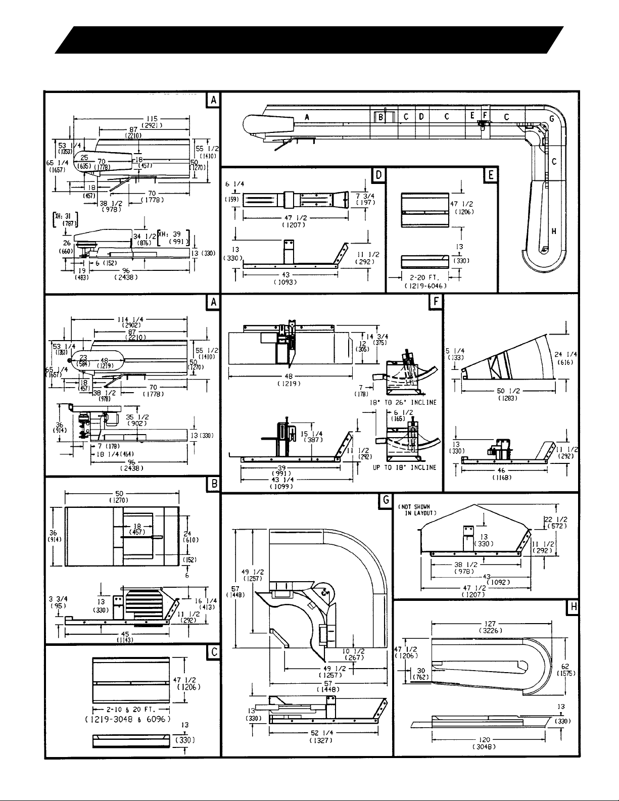
Dimensions
DOUBLETROUGH,STEEL,SLANTED60°SIDEWALL
BOLT-TOGETHER SECTIONS
ALLCOMPONENTS:18”(457)TROUGHWIDTH
DIMENSIONS: INCHES (MM)
203, HVY. & XH REDUCER DRIVE UNIT
&FRONTSLIDE(8FT.SHOWN)
7°ELBOWSECTION
TRAPDOOR SECTION
90° CORNER SECTION COVER ASSEMBLY
10’180°ENDSECTION
CENTER SLIDE
REAR SLIDE
22.5° SL. CORNER SECTION
(NOT SHOWN IN LAYOUT)
PLANETARY DRIVE UNIT & FRONT
SLIDE(8FT.SHOWN)
HOLD DOWN POST SECTION WITH SHOE
AND RETURN GUIDE

8
Dimensions
DOUBLE TROUGH, STEEL, 90° STRAIGHT SIDEWALL
BOLT-TOGETHER SECTIONS
ALLCOMPONENTS:18”(457)TROUGH
DIMENSIONS: INCHES (MM)
203, HVY. & XH REDUCER DRIVE UNIT
&FRONTSLIDE(8FT.SHOWN)
7°ELBOWSECTION
TRAPDOOR SECTION
90° CORNER SECTION COVER ASSEMBLY
10’180°ENDSECTION
CENTER SLIDE
REAR SLIDE
22.5° SL. CORNER SECTION
(NOT SHOWN IN LAYOUT)
PLANETARY DRIVE UNIT & FRONT
SLIDE(8FT.SHOWN) HOLD DOWN POST SECTION WITH SHOE
AND RETURN GUIDE

Proposed Layout: 1/4” = _____ft.
Dealer/Distributor: _____________________________
Address: ____________________________________
____________________________________
Phone: ______________________________________
Fax: ________________________________________
E-mail: ______________________________________
Customer: ___________________________________
Address: ____________________________________
____________________________________
Phone: ______________________________________
Fax: ________________________________________
E-mail: ______________________________________
Date: ______________________________________
By: ________________________________________
Patz Corporation, P.O. Box 7, Pound, WI 54161-0007 Phone: 920-897-2251 Fax: 920-897-2142 [email protected] www.patzcorp.com
Copyright ©2001-2017 Patz Corporation

Table of contents
Popular Accessories manuals by other brands

Panasonic
Panasonic ECONAVI CZ-CENSC1 operating instructions

B&PLUS
B&PLUS RS12T-TF423A-TP01 instructions

Vericon Systems
Vericon Systems MultiDOT quick start guide

Movisens
Movisens EdaMove 3 user manual

iOptron
iOptron SmartStar Cube E Series instruction manual

Monacor
Monacor JTS MA-HPF operating instructions


