Pavone Systems 1006 User manual

Pavone Sistemi
pesatura elettronica industriale
TECHNICAL MANUAL
TESTER 1006 For the simultaneous monitoring of up to 4 load cells
Software version PMT 401 Rel. 1.5

2
THE USE OF THE INSTRUMENT
KEY FUNCTIONS IN OPERATING MODE Page 11
KEY FUNCTIONS WITHIN THE VARIOUS MENUS Page 12
OPERATING MODE : DATA VISUALIZATION Page 14
“WEIGHING PARAMETERS” MENU Page 15
ADDITIONAL FUNCTIONS Page 18
DISPLAY INTENSITY ADJUSTMENT Page 20
THE “CALIBRATOR” FUNCTION Page 21
ACCESSORIES, OPTIONS AND SPARE PARTS Page 23
POWER-ON SEQUENCE Page 13
INSTRUMENT’S FEATURES
TECHNICAL SPECIFICATIONS Page 3
POWER SUPPLY AND BATTERY REPLACEMENT Page 4
CONNECTIONS
CONNECTION TO THE LOAD CELLS with Cable “A” Page 7
CONNECTION TO THE LOAD CELLS with Cable “B” Page 8
USING THE LOAD CELL TESTER IN “CALIBRATOR” MODE WITH J1/CB BOARD Page 9
MAIN PERFORMANCES Page 5
SWITCHING BETWEEN LOAD CELL TESTER AND CALIBRATOR MODES Page 6
CGS4/C and CEM4/C SUMMING JUNCTION BOXES Page 10
USING THE LOAD CELL TESTER IN “CALIBRATOR” MODE WITH J2/CB BOARD Page 9
CONTENTS
APPENDIX A
CONFIGURATION FILES MANAGEMENT Page 28
ACCESSING THE CONFIGURATION FILES MENU Page 30
SAVING A FILE Page 31
OPENING A FILE Page 34
DELETING ONE FILE / ALL FILES Page 38
TRANSFERRING ONE FILE / ALL FILES Page 39
STORING THE mV/V LOAD CELLS SIGNALS Page 42
STORED mV/V LOAD CELLS SIGNALS VISUALISATION Page 44
GENERATING THE STORED mV/V LOAD CELLS SIGNALS Page 45
UPLOAD/DOWNLOAD SET UP FILE INSTRUMENTS Page 23
RS 232 CONNECTION Page 46

3
TECHNICAL SPECIFICATIONS
Instrument power supply
Current consumption
Operating temperature
Storage temperature
Display
Keyboard
Overall dimensions
Weight
Enclosure
Protection degree (front)
Connection to load cells
With Cable A (std) or Cable B(option)
Load cells excitation voltage
4 individual load cell channels with the
following specs:
Linearity
Internal resolution
Displayed weight resolution
Input signal range
Decimal digits
Battery life
Accuracy of the mV/V signal generated
in Calibrator mode
4 x 1.5 V alkaline disposable batteries -AA size-
or:
4 x 1.2 V Ni-MH rechargeable batteries -AA size-
Min. 125 mA - Max. 190 mA
+ 14°F to + 122°F (-10°C to +50°C)
- 4°F to + 158°F (-20°C to +70°C)
Graphic, 3”
16 keys + On / Off switch
8.66 x 4.60 x 2.00 in. (220 x 117 x 51 mm.) H x W x D
Approximately 1.1 lbs. (500 Grams)
Polyamide (UL94 - V2)
IP 54
“A” type: 6 foot (2 m) cable with 25 pin Sub-D connectors
“B” type: (0,3 m) serial cable
5 Vdc @ 60 mA (4 x 350 Ω load cells) max.
< 0.01% of Full Scale
24 bit
Up to 50.000 counts
-3.9 mV/V to +3.9 mV/V
Up to 3
About 4 hours with disposable batteries
About 8 hours with Ni-MH batteries (2000 mAh)
0.033% of Full Scale (1/3000)
Load cell cnnections
LC Tester side Load cell connections
Standard “B” type cable
Standard “A” type cable with 25 pin Sub-D connectors
LC’s excitation voltage input range
mV signal output range
Min: 3 Vdc Max: 15 Vdc
Min: -3.0 mV Max: +20.3 mV
Load cells impedance 350/700 Ωselection, or min. 300 to max. 4500 Ω setting.
LC Tester side PC or weight instrument

4
POWER SUPPLY AND BATTERIES REPLACEMENT
The Load Cell Tester is powered by “AA” size batteries :
Use four x 1.5 V Alkaline Disposable Batteries or 1.2 V Ni-MH Rechargeable Batteries
The battery life depends on the number of load cells being powered and the intensity level of the LCD display.
Min. consumption is about 125 mA (single 350 Ω load cell with display intensity at intermediate level).
Max. consumption is about 190 mA (four 350 Ω load cells with display intensity at maximum level).
The life of alkaline disposable batteries is about 4 hours in continuous operating mode*, at the max.
consumption.
The life of the Ni-MH rechargeable batteries depends on their capacity (expressed in mA per hour).
For example, with 4 x 2000 mAh batteries, the battery life is over 8 hours in continuous operating mode*, at
the max. consumption (2000 mAh/190 mA = 10,5 h).
Even though the theoretical limit exceeds 10 hours, the auto shut-off takes place sooner in order to assure
the full functionality of the Load Cell Tester and to avoid completely discharging the batteries.
*By “continuous operating mode” we mean that the Load Cell Tester switched-on continuously.
Setting the “auto shut-off” parameter will extend the battery life (see page 16 for additional information).
BATTERY REPLACEMENT
LC TESTER: Rear view
Remove the 3 screws indicated by the arrows
Gently raise side A of the cover and slide it out.
Replace the 4 batteries as required, observing
polarity as marked on the battery holder
(See figure below).
Reposition the cover in its seat
Replace the 3 screws
Side “A”
The manufacturer waives all responsibility for any damage to the Load Cell Tester
caused by the use of batteries other than those listed above.
+
-
+
-
+
-
+
-

5
MAIN PERFORMANCES
Even if the 2 main functions performed by the Load Cell Tester are independent, they
allow to carry out the complete analysis of any weighing system composed by load cells (up
to 4) and weight indicator.
Function for testing the load cells
This mode is used to diagnosis the load cells.
The display shows the following group of parameters:
1. The signals coming from the load cells (mV/V values)
2. The distribution of the weight on the load cells (% values)
3. Load on each load cell compared with its nominal capacity (% values)
4. Weight value on each load cell (expressed in the selected measurement unit: g, kg,
Ton, lb, N, kN)
Values 3 and 4 are only displayed if the parameters described on pages 15 to 17 have been
programmed.
Faulty load cells or bad connections*, zero offset drifts or unstable signals can be easily
detected.
* These messages appear on the display in the following conditions:
1. “EXC +” indicates a problem with the + Excitation lead
2. “EXC -” indicates a problem with the - Excitation lead
3. “SIGNAL” indicates a problem with one of the Signal leads
Load Cells Peak Function
The 1006 Tester in this operating mode allows to view the peak values of each load cell.
The peak value cab be enabled or disabled, for all the 4 groups of parameters above
described by pressing long the key 5. To erase peak values detected, press key C.
Transducer Simulator / Calibrator Mode
In this mode the load cell tester is used to calibrate or check out the weight indicator.
A signal of up to 20 mV can be generated and used to check the linearity and to check or
calibrate the Zero and Span of any weighing instrument.
mV/V signal to instrument mV signal to instrument
% of output signal
Excitation from instrument Weight value
mV/V bar-graph (0 - 100%)
Transducer Simulator
Output Signal
+ 1.600mV/V + 7.920mV
V in +4.95
+ 80%
GW 800 kg
6
mV/V Input Signals
1 2
3 4
1.024 1.131
0.978 0.856
Test
Cal
Transducer Simulator
Output Signal
+ 1.600
mV/V + 7.920
mV
V in +4.95
+80%
GW 800 kg
Test
Cal
Test
Cal
Test
Cal
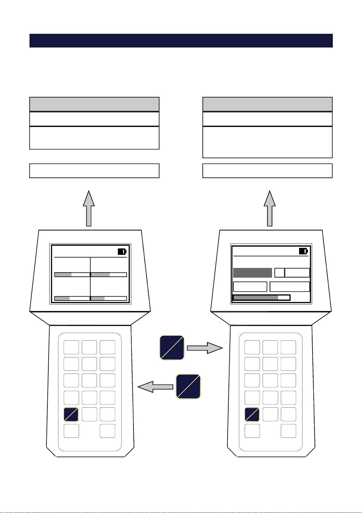
SWITCHING BETWEEN “LOAD CELL TESTER” AND “CALIBRATOR” MODES
Switching between the 2 functions (as described on the previous page) is performed by
pressing the Test/Cal key:
LOAD CELL TESTER
Function
Operating mode described on page 14
CALIBRATOR/SIMULATOR
Function
Oper. mode described on page 21, 22
To be used exclusively for testing
the load cells To be used exclusively for testing
and calibrating the weighing
instrument.
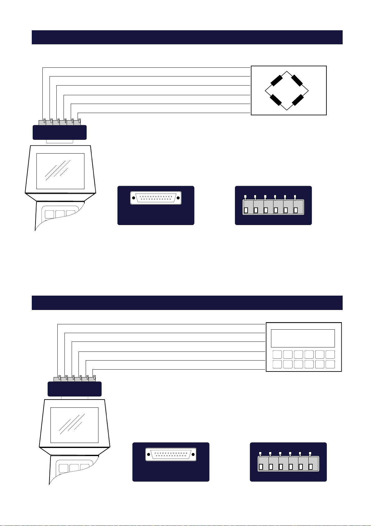
7
Cable “A”, terminates with a 25 pin female Sub-D connector and is supplied with the J1/PT Screw
Terminal Board.
CONNECTION TO THE LOAD CELLS with Cable “A”
L.C. 4
L.C. 1
L.C. 2
L.C. 3
L.C. 1
L.C. 2
L.C. 3
L.C. 4
CGS4/C CEM4/C
Connection using Cable “A” to CGS4/C
Connection using Cable “A” to CEM4/C
Connection using Cable “A” to CGS4/C junction Board
LC’s Tester side
LC’s Tester side
If the existing installation is equipped with model CGS4/C or model CEM4/C summing junction
board, only connect Cable “A” directly to the 25 pin Sub-D connector on the board, without using
the J1/PT Board.
LC’s Tester side
CGs
Cella 1
Cella 2
Cella 3
Cella 4
8
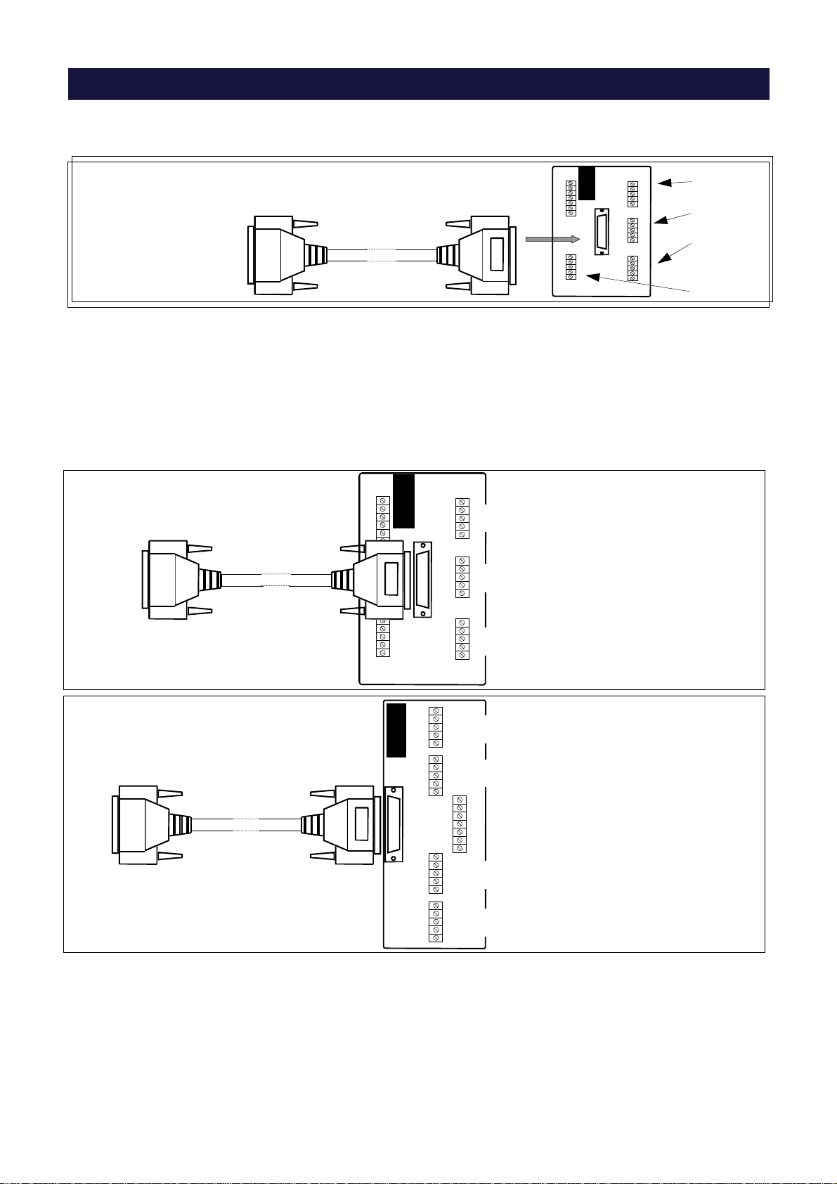
USING THE LOAD CELL TESTER IN “CALIBRATOR” MODE WITH J1/CB
USING THE LOAD CELL TESTER IN “CALIBRATOR” MODE WITH J2/CB BOARD
LC TESTER SIDE
Instrument to be
calibrated
888888
+ Excitation
- Excitation
+ Signal
- Signal
- Sense
+ Sense
INSTRUMENT SIDE
-Exc +Exc +Sns -Sns -Sig +Sig
The J2/CB Calibration Board, supplied with cable “B”,provides another
method of connecting to the weight indicator when using the load cell
tester in “Calibrator” mode. See above illustration for wiring connections.
LC TESTER SIDE
Load cell to be
checked
+ Alimentazione
- Alimentazione
+ Segnale
- Segnale
- Sense
+ Sense
INSTRUMENT SIDE
-Exc +Exc +Sns -Sns -Sig +Sig
The card J1/CB board, supplied with the cable "B", provided allows
the use of the tester for checking the load cell.
See above illustration for wiring connections
9
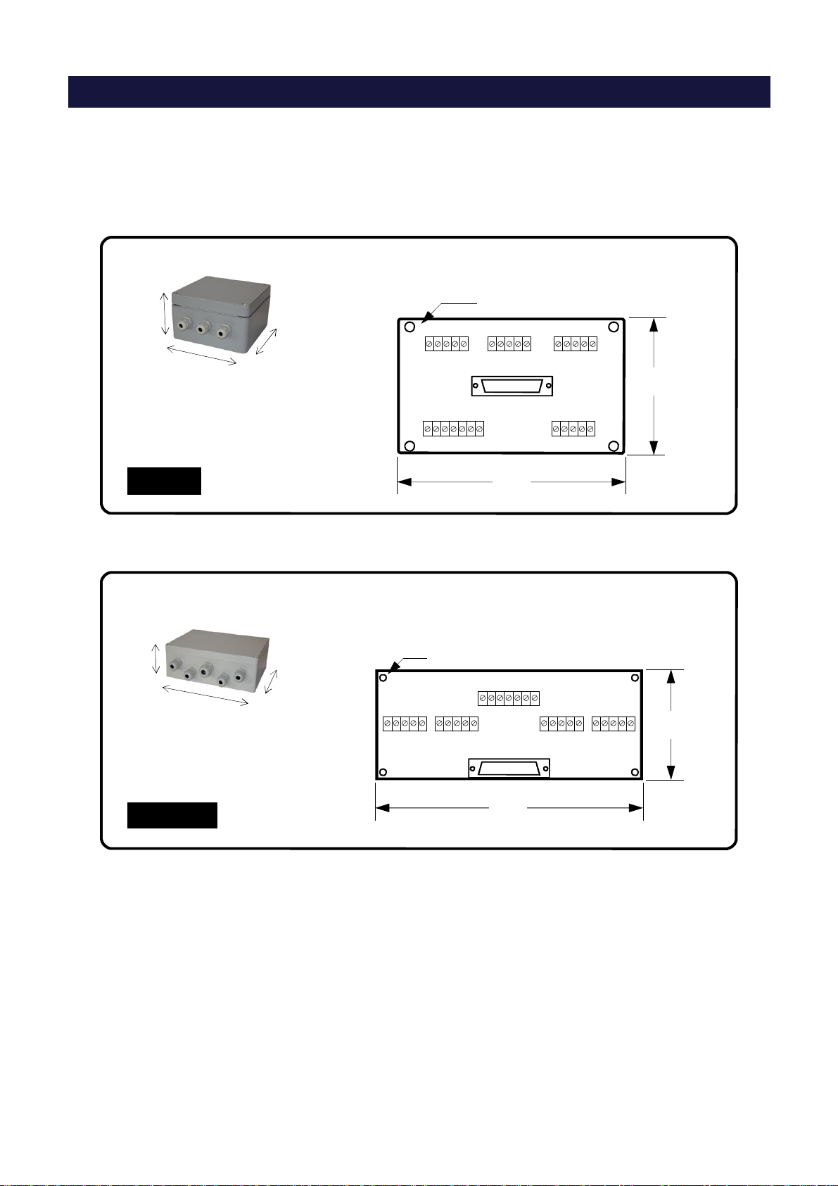
CGS4/C and CEM4/C SUMMING JUNCTION BOXES
The CGS4/C and CEM4/C summing junction boxes, are equipped with a 25 pin
Sub-D connector, which provides a quick reliable connection to the Model 1006
LC System Tester with standard Cable “A”.
In order to use the LC System Tester on weighing systems using summing
J-boxes other than the CGS4/C or CEM4/C, we are offering our customers
a free evaluation for installing a 25 pin Sub-D connector on their own summing
junction boards.
If you would like to take advantage of this offer, we would require detailed
drawings or a sample of the summing J-Boxes that you are currently using.
CGS4/C
CEM4/C
70
170
Ø 5
Box Dimensions
(mm)
87
146
Ø 6,5 Board Dimensions
(mm)
160
160
90
150
200
90
Box Dimensions
(mm)
Board Dimensions
(mm)

10
KEY FUNCTIONS IN OPERATING MODE
3
C .
Enter
0
Switch
view
+
Test
Cal
Display intensity adjustment (see page 20)
Switching between LOAD CELL TESTER and CALIBRATOR modes
Navigating through the various display views in LOAD CELL TESTER mode (see page 14)
Access to configuration menu
Short press: access to “WEIGHING PARAMETERS” (see page 15)
Long press: access to “ SETUP MENU” (see page 17)
Zero the weight value in CALIBRATOR mode (see page 21)
Erase the zero of the weight value in CALIBRATOR mode (see page 21)
Fine increment of the mV/V output signal in CALIBRATOR mode (see page 21)
Fine decrement of the mV/V output signal in CALIBRATOR mode (see page 21)
Switch-off
8
2Coarse increment (in 0.1 mV/V steps) of the output signal in CALIBRATOR mode (see page 21)
Coarse decrement (in 0.1 mV/V steps) of the output signal in CALIBRATOR mode (see page 21)

11
They take meaning of “Arrow up” and “Arrow down”.
They allow to select the previous/next parameter from a list of parameters proposed by
the instrument
8
2
6 Takes meaning of “Arrow right”.
Allows to access the parameter previously selected with Arrow up/down keys.
4
Sometimes the selection of a certain parameter is performed with these keys instead of
with the Arrow up/down keys.
The symbols +and —appear on the display to inform the Operator.
KEY FUNCTIONS WITHIN THE VARIOUS MENUS
Data Selection (from a list)
Takes meaning of “Arrow left”.
Exits the menu without saving the changes
Enter Exits the menu after saving the changes
+
Entering Numerical Data
90 ……
C .
Enter
Keys 0 to 9 are used to program all those parameters requiring numerical
values, such as the load cell capacity, etc.
This key performs 2 functions:
1. Used to insert a decimal point in numerical values.
2. Used to erase the data: Press momentarily to erase the last digit
Press slightly longer to erase all of the data
Confirm and quit the settings.

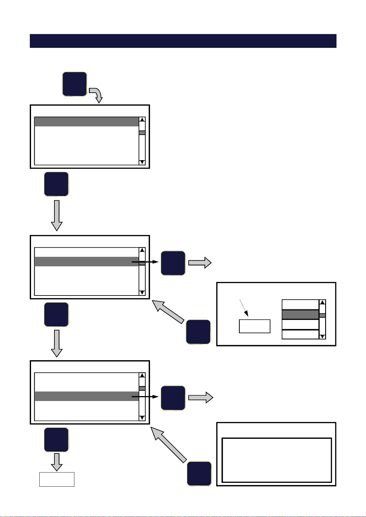
12
LC System Tester
Firmware: PMT401
Rev. 1.3
Number of Load Cells
1
Enter
Select
Confirm
2
3
4
Selection
Confirm
8
2
Enter
Power-ON:
POWER-ON SEQUENCE
LC’s impedance
Enter
Confirm
350
700
Ω
Ω
Ω
350
700
Enter
mV/V Input signals
1 2
3 4
1.024 1.131
0.978 0.856
Impedance value
1000
3
2
1 Enter
The value can be selected
between 350 and 700Ω, otherwise
it can be programmed by
choosing the empty box in the
lower part of the display.
Once the value has been set, the
LC Tester enters the Operating
Mode automatically.
8
2
Selection
Operating Mode
Enter
Min. programmable value: 300Ω
Max. programmable value: 4500Ω
Decimal values will be automatically rounded
to the lower integer value.
When powering-on the LC Tester the following parameters must be programmed:
Number of load cells - Load cells Impedance.
NOTE:
The firmware code and
the release number
appear on the display
for about 3 seconds:
In case the last switch-off of the LC Tester was caused
by the Auto Shut Off function (see page 18), the LC
Tester immediately resumes the Operating
Mode,without asking for the LC’s Number and
Impedance to be programmed.
The instrument’s memory will keep the stored values.

13
mV/V Input Signals
1 2
3 4
1.024 1.131
0.978 0.856
Weight Distribution
1 2
3 4
25.6 % 28.3 %
24.6 % 21.5 %
% of load on LC’s
1 2
3 4
51.2 % 56.6 %
49.2 % 43.0 %
Weight Values
1 2
3 4
128.0 141.5
123.0 107.5 Distribution of the weight on the load cells
Ideal distribution: 25% each LC
Individual mV/V values coming from the
load cells
Load on each load cell compared to its
nominal capacity
Weight value on each load cell. Expressed
in the selected unit of measurement.
NOTE: Display views 3(% of load on LC’s) and 4(Weight values) give significant values only if the load cell single
capacity and sensitivities have been programmed.
OPERATING MODE : DATA VISUALIZATION
Switch
view
1
2
3
4
During normal operation in Load Cell Tester mode (see page 6), the “SWITCH VIEW” key switches the display
among 4 different views.
Switch
view
Switch
view
Switch
view
14
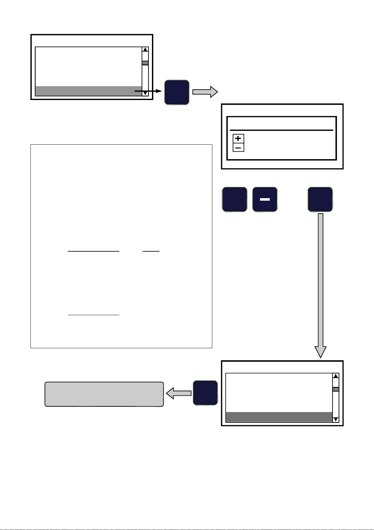
8
“WEIGHING PARAMETERS” MENU
In Operating Mode:
Enter
Press
Unit of Measurement
Number of Load Cells
Load Cell Capacity
LC Sensitivity Values
Display Division Value
WEIGHING PARAMETERS
8
8
Unit of Measurement
Number of Load Cells
Load Cell Capacity
LC Sensitivity Values
Display Division Value
WEIGHING PARAMETERS
6 Measurement unit selection, with and .
The selected unit of measurement appears
in the box on the left of the screen.
Enter kg
Unit of Measurement
g
kg
Ton
lb
Unit of Measurement
Number of Load Cells
Load Cell Capacity
LC Sensitivity Values
Display Division Value
WEIGHING PARAMETERS
6 Enter the nominal capacity of a single load
cell.
The instrument automatically multiplies
the single load cell capacity by the
“Number of LC’s” being used.
Enter
Enter capacity
of a single LC
250 kg
Load Cell Capacity
Page 16

15
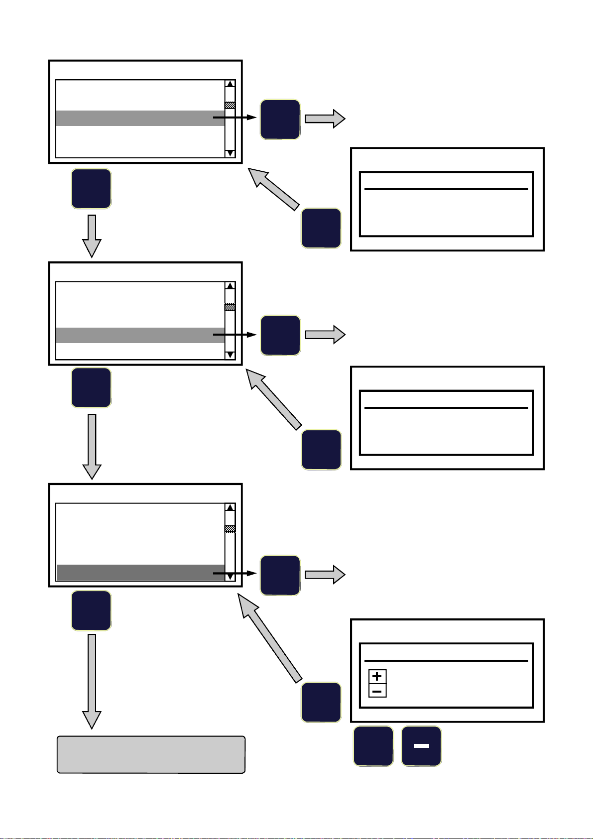
8
Unit of Measurement
Number of LC’s
Load Cell capacity
LC Sensitivity Values
Display Division Value
WEIGHING PARAMETERS
6
Setting the nominal sensitivity (in mV/V)
of each single load cell.
Take the data from the calibration
certificates or from the labels sticked on
the load cells.
Enter
2.0000 mV/V
2.0000 mV/V
2.0000 mV/V
2.0000 mV/V
L.C. 1
L.C. 2
L.C. 3
L.C. 4
LC Sensitivity Values
6
L.C. 1 mV/V
2.0108
LC Sensitivity Values
3
2
1
2.0108 mV/V
2.0000 mV/V
2.0000 mV/V
2.0000 mV/V
L.C. 1
L.C. 2
L.C. 3
L.C. 4
LC Sensitivity Values
8
6
L.C. 2 mV/V
2.0067
LC Sensitivity Values
3
2
1
Setting the nominal sensitivity of
LC 1
Setting the nominal sensitivity of
LC 2
Perform the same procedure for the remaining load cells
4
Page 17
16
WEIGHING PARAMETERS
6 Selection of the Display division value
Display Division Value
0.1
The Display division value can be selected from a list (0.001 to
100, expressed in the measurement unit previously enabled).
The LC Tester automatically offers a value optimised to 10000
counts, based on the nominal capacity of the load cells (sum
of the load cell’s single capacities).
Example: Single LC capacity = 250
Number of load cells = 4
LC’s Total capacity (250 x 4) = 1000
The Display division value automatically offered by the LC
Tester will be: 0.1 given by the ratio:
LC’s Total capacity _1000_
10000 10000
However the User has the chance to modify this value (+ or -),
bearing in mind that the maximum number of counts can
be 50000.
Considering the example given here above, the ratio:
LC’s Total capacity
50000
equals 0.02.
This will be the minimum usable Display division value.
Enter
+
Selection Confirm
Unit of Measurement
Number of LC’s
Load Cell Capacity
LC Sensitivity Values
Display Division Value
WEIGHING PARAMETERS
4
Exits the menu and returns
to Operating Mode
Unit of Measurement
Number of LC’s
Load Cell Capacity
LC Sensitivity Values
Display Division Value
= 0.1

17
8
8
ADDITIONAL FUNCTIONS
In Operating Mode:
Enter
Press
and hold
Set Date (MM/DD/YYYY)
Auto Shut Off
Set Time
LCD Contrast
Baud Rate
SETUP MENU
5 MIN
Auto Shut Off
OFF
3 MIN
5 MIN
10 MIN
6
Enter
Automatic shut off time delay selection.
The selected value appears in the box on
the left of the screen.
The LC Tester switches off automatically if
no keys are pressed within the selected
time delay.
The countdown is restored if any of the
keys is pressed within the selected time
delay.
“OFF” = function disabled.
Page 19
LCD Contrast
575
SETUP MENU
6
Enter
LCD contrast adjustment.
+Adjustment
Set Date (MM/DD/YYYY)
Auto Shut Off
Set Time
LCD Contrast
Baud Rate
SETUP MENU
18
Set Time
16:45
SETUP MENU
6
Enter
Setting the Date
Max. values: 12 (month)
31 (day)
2050 (year)
6
Enter
Setting the Time
Max. values: 23 (hour)
59 (minutes)
8
8
Set Date (MM/DD/YYYY)
Auto Shut Off
Set Time
LCD Contrast
Baud Rate
SETUP MENU
Set Date (MM/DD/YYYY)
Auto Shut Off
Set Time
LCD Contrast
Baud Rate
SETUP MENU
RS-232 Baud Rate
9600
SETUP MENU
Set Date (MM/DD/YYYY)
Auto Shut Off
Set Time
LCD Contrast
Baud Rate
SETUP MENU
6
Enter
RS-232 baud rate selection.
List of values:
1200 - 2400 - 4800 - 9600 - 19200 -
38400 - 57600
+Selection
4
Exits the menu and returns
to Operating Mode
Set Date (MM/DD/YYYY)
09/20/2006
SETUP MENU
19
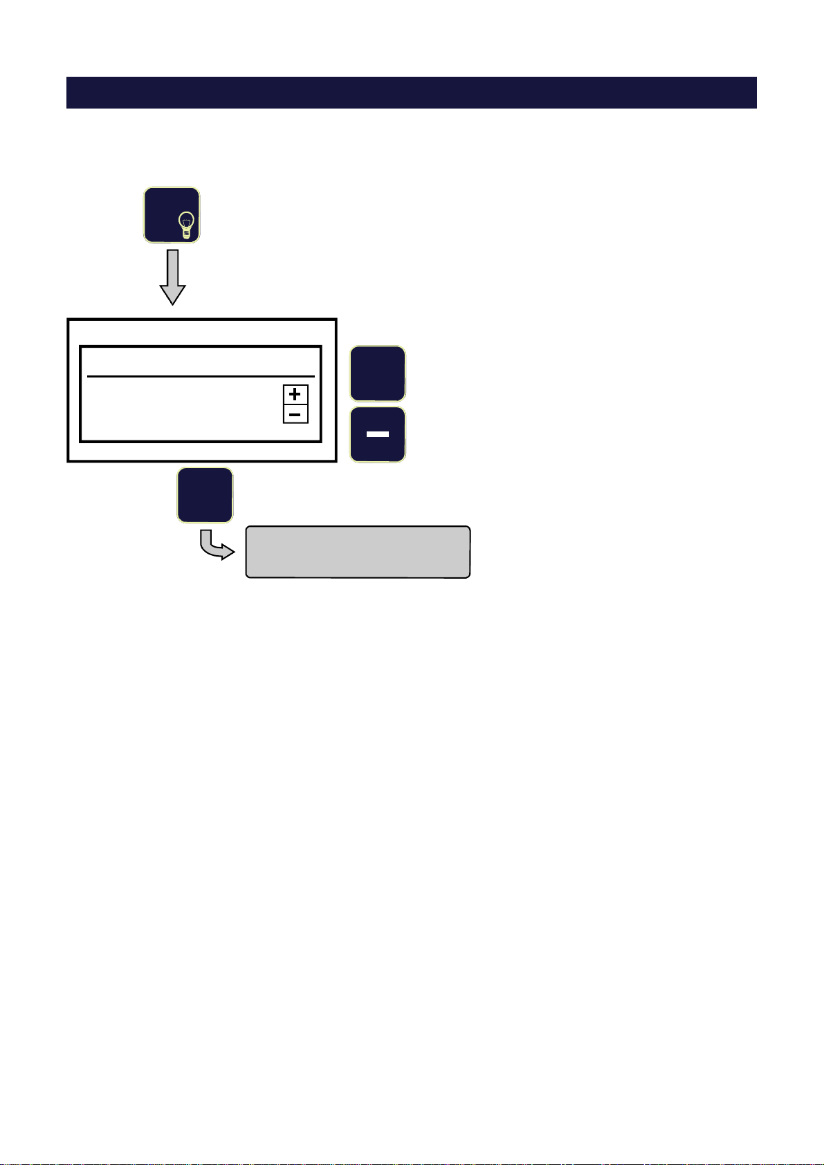
4
DISPLAY INTENSITY ADJUSTMENT
In Operating Mode:
Press 3
Display Intensity
+ / - keys to adjust
key to exit 5
Confirm and return to
Operating Mode
+Increases Intensity
Reduces Intensity

20
THE “CALIBRATOR” FUNCTION
How to enable the function:
Press Test
Cal Transducer Simulator
Output Signal
+ 1.600mV/V + 7.920mV
V in +4.95
+ 80%
GW 800 kg
Displayed data
+ 1.600mV/V
V in +4.95
+ 7.920mV
PL 900 kg
+ 80%
mV/V signal generated by the LC Tester and sent to the instrument.
The and keys allow to generate the signal output (in steps of 0.1 mV/V) over a
range from 0 to FS.
The mV/V Full Scale value corresponds to the average of the individual mV/V load cell
sensitivities programmed in the “WEIGHING PARAMETERS” menu. See page 16.
Load cells excitation voltage coming from the instrumentation.
mV signal generated by the LC Tester and sent to the instrument.
This value is the product of “mV/V” multiplied by “Vin”.
Weight value corresponding to the mV/V signal generated by the LC Tester.
The weight value is expressed in the preselected measurement unit and its Full Scale is
the product of “Single LC capacity” multiplied by “Number of LC’s”, programmed in the
“WEIGHING PARAMETERS” menu.
Percentage of signal output referred to the Full Scale.
Through this function the LC Tester acts as a mV generator, therefore it can be used as a load cell simulator
and/or calibrator for electronic weighing instruments, to check linearity, to check 0 and FS, to perform 0 and FS
calibration.
Refer to page 9 for wiring.
In order for the “CALIBRATOR” function to work correctly, the following parameters
“Number of LC’s”, “LC’s sensitivity” and “Single LC capacity” programmed in the LC Tester
must be the same as those programmed in the instrument to be controlled.
Example:
If the instrument to be controlled is normally connected to 4 load cells 250 kg each, 2 mV/V,
the LC Tester must have been programmed with the same data (see pages 15-17):
Number of LC’s = 4 - LC’s sensitivity = 2.0000 - Single LC capacity = 250.
Table of contents


