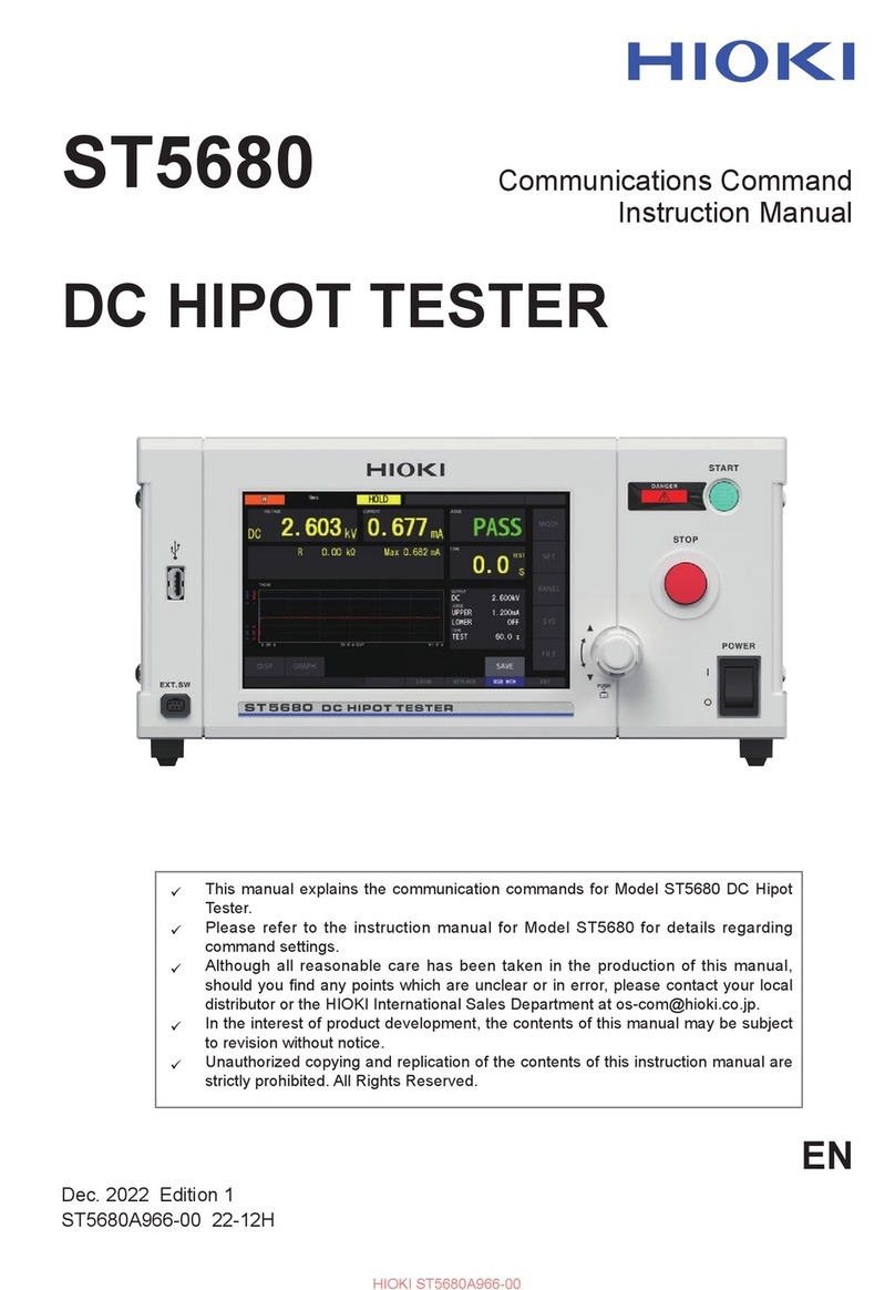
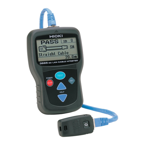
Hioki 3154 User manual

Hioki 3154 Manual
Get Pricing & Availability at
ApexWaves.com
Call Today: 1-800-915-6216
Email: sales@apexwaves.com
https://www.apexwaves.com/analyzers/hioki/digital-m-ohm-hitesters/3154

DIGITAL MΩHiTESTER
INSTRUCTION MANUAL
3154


Contents
Introduction i
Inspection ii
Safety Notes iii
Notes on Use vii
Chapter 1 Outline 1
1.1 Product Introduction 1
1.2 Features 1
1.3 Controls and Functions 3
1.3.1 Displays 3
1.3.2 Front Panel 4
1.3.3 Rear Panel 5
Chapter 2 Preparation for Testing 7
2.1 Connecting Power Cord 8
2.2 Powering On and Off the Unit 9
2.3 Connecting Cord and Probes
(9257, 9289, 9294) 10
2.4 Using Handle 11
2.5 Connecting to Equipment to be tested 12
Chapter 3Setting Basic Testing Conditions 13
3.1 Setting Test voltage 14
3.2 Setting and Verifying Comparator 15
3.2.1 Setting Lower Limit Value 15
3.2.2 Setting and Verifying Test mode 17
3.3 Setting and Verifying Resistance Range 18
3.4 Setting and Verifying Timer 19
3.4.1 Setting and Verifying Test Duration 19
3.4.2 Setting and Verifying Delay Time 21
3.4.3 Determining Delay Time 23

3.5 Setting Sampling Rate 25
3.6 Example Test Condition Setting 26
Chapter 4 Testing 29
4.1 Test Flow 30
4.2 Start Testing 31
4.3 During Testing (TEST status) 32
4.4 Measurement Value Display 33
4.5 Completing Testing 34
4.6 Automatic Discharge 35
4.7 Testing with 9299 SWITCHED PROBE 36
4.7.1 Connecting 9299 SWITCHED PROBE 37
4.7.2 Setting 9299 SWITCHED PROBE 38
Chapter 5 Other Functions 39
5.1 Setting and Verifying Beep Sound 40
5.1.1 Setting Judgment Beep Sound 40
5.1.2 Setting Beep Sound During Key Press 41
5.2 Saving and Loading Test Conditions 42
5.2.1 Saving Test Conditions 42
5.2.2 Loading Test Conditions 44
5.3 Key Lock Function 45
5.4 System Reset 46
Chapter 6 External Interface 47
6.1 Controlling 3154 with External I/O 47
6.1.1 Terminal Connector Board/Signal Wires 48
6.1.2 Electric Specifications 50
6.1.3 Connecting External I/O Terminal 52
6.1.4 External I/O Terminal Circuit 54
6.1.5 Settings to be selected with VOLT 0 to 2
signals 55
6.1.6 Setting TEST Signal OFF Timing 57
6.1.7 Timing Chart 59
6.1.8 Output Signal Connection Example 61
6.1.9 Input Signal Connection Example 62

6.2 Analog Outputting 63
6.2.1 Connecting the 9094 OUTPUT CORD 63
6.2.2 Analog Output 64
6.2.3 Setting Analog Output 65
6.3 Outputting to Printer 66
6.3.1 Connecting Printer 70
6.3.2 Printing Example 71
Chapter 7 RS-232C Interface 73
7.1 Controlling from Personal Computer 74
7.1.1 Preparing for Data Transfer 75
7.1.2 Communication 77
7.1.3 Command Format 78
7.1.4 Numeric Format Chart 82
7.1.5 Command Reference 83
7.2 Sending Measurement Data to PC 97
Chapter 8 Specifications 101
8.1 General Specifications 101
8.2 Measurement Part Specifications 103
8.3 Dimensions 109
8.4 Options and specifications 110
Chapter 9 Maintenance and Service 113
9.1 Maintenance and Inspection 113
9.2 Trouble shooting 114


i
_____________________________________________________________________
Introduction
______________________________________________________________
Introduction
Thank you for purchasing the HIOKI "3154 DIGITAL MΩ
HiTESTER." To obtain maximum performance from the
product, please read this manual first, and keep it handy for
future reference.
Changes to Specifications
Changes are made to software version 1.10.
Software version appears following the model name (3154)
after start up.
・Measurement range is expanded up to 4000 MΩwith
test voltage at 500 V.
・Analog output voltage is changed from 4 V to 2 V when
2000 MΩis displayed with test voltage at 500 V.
・Outputs 4 V output with analog output at each resistance
range maximum value.
・Wider key entry selections to set lower limit values.
・Saved test conditions can be loaded using external I/O
VOLT 0 to 2 signals.
・External I/O TEST signal OFF timing setting display
appears as "tEStSIGnAL".
・The following four RS-232C commands are added;
:VOLTage:SIGNaL
:VOLTage:SIGNaL?
:AOUT:RANGe
:AOUT:RANGe?

ii
_____________________________________________________________________
Inspection
______________________________________________________________
NOTE TEST PROBES are not included. Please purchase separately
according to your needs.
Ins
p
ection
When you receive the product, inspect it carefully to ensure
that no damage occurred during shipping. In particular,
check the accessories, panel switches, and connectors. If
damage is evident, or if it fails to operate according to the
specifications, contact your dealer or Hioki representative.
Accessories
Verify that following standard accessories are complete.
Instruction Manual 1
Grounded three-core power cord 1
Shipment of the unit
Use the original packing materials when reshipping the
product, if possible.
Warranty
HIOKI cannot be responsible for losses caused either
directly or indirectly by the use of the 3154 with other
equipment, or if ownership is transferred to a third party.

iii
_____________________________________________________________________
Safety Notes
______________________________________________________________
WARNING
This product is designed to conform to IEC 61010
Safety Standards, and has been thoroughly tested for
safety prior to shipment. However, mishandling during
use could result in injury or death, as well as damage
to the product. Be certain that you understand the
instructions and precautions in the manual before use.
We disclaim any responsibility for accidents or injuries
not resulting directly from product defects.
Safety Symbols
The symbol printed on the product indicates that the
user should refer to a corresponding topic in the
manual (marked with the symbol) before using the
relevant function.
In the manual, the symbol indicates particularly
important information that the user should read before
using the product.
Indicates the ON side of the power switch.
Indicates the OFF side of the power switch.
Indicates that dangerous voltage may be present at
this terminal.
Indicates AC (Alternating Current).
Indicates DC (Direct Current).
Safet
y
Notes
This manual contains information and warnings essential
for safe operation of the product and for maintaining it in
safe operating condition. Before using the product, be sure
to carefully read the following safety notes.

iv
_____________________________________________________________________
Safety Notes
______________________________________________________________
DANGER
Indicates that incorrect operation presents an extreme
hazard that could result in serious injury or death to
the user.
W
ARNING
Indicates that incorrect operation presents a
significant hazard that could result in serious injury or
death to the user.
CAUTION Indicates that incorrect operation presents a
possibility of injury to the user or damage to the
product.
NOTE Advisory items related to performance or correct
operation of the product.
The following symbols in this manual indicate the relative
importance of cautions and warnings.

v
_____________________________________________________________________
Safety Notes
______________________________________________________________
CAT I Secondary electrical circuits connected to an AC
electrical outlet through a transformer or similar
device.
CAT II Primary electrical circuits in equipment connected
to an AC electrical outlet by a power cord (portable
tools, household appliances, etc.)
CAT III Primary electrical circuits of heavy equipment
(fixed installations) connected directly to the
distribution panel, and feeders from the distribution
panel to outlets.
CAT IV The circuit from the service drop to the service
entrance, and to the power meter and primary
overcurrent protection device (distribution panel).
Measurement categories (Overvoltage categories)
This product complies with CAT I safety requirements.
To ensure safe operation of measurement product, IEC
61010 establishes safety standards for various electrical
environments, categorized as CAT I to CAT IV, and called
measurement categories. These are defined as follows.
Higher-numbered categories correspond to electrical
environments with greater momentary energy. So a
measurement device designed for CAT III environments can
endure greater momentary energy than a device designed for
CAT II. Using a measurement product in an environment
designated with a higher-numbered category than that for
which the product is rated could result in a severe accident,
and must be carefully avoided.
Never use a CAT I measuring product in CAT II, III, or IV
environments. The measurement categories comply with the
Overvoltage Categories of the IEC60664 Standards.

vi
_____________________________________________________________________
Safety Notes
______________________________________________________________
f.s. (maximum display value or scale length)
The maximum displayable value or the full length of the
scale.
This is usually the maximum value of the currently
selected range.
rdg. (reading or displayed value)
The value currently being measured and indicated on the
measuring product.
dgt. (resolution)
The smallest displayable unit on a digital measuring
product, i.e., the input value that causes the digital
display to show a "1".
Accuracy
We define measurement tolerances in terms of f.s. (full
scale), rdg. (reading) and dgt. (digit) values, with the
following meanings:

vii
_____________________________________________________________________
Notes on Use
______________________________________________________________
DANGE
R
To avoid electric shock, do not remove the product's
case. The internal components of the product carry
high voltages and may become very hot during
operation.
WARNING
Before using the product, make sure that the insulation
on the test probes is undamaged and that no bare
conductors are improperly exposed. Using the product
under such conditions could result in electrocution.
Replace the test probes specified by Hioki .
Do not use the product where it may be exposed to
corrosive or combustible gases. The product may be
damaged or cause an explosion.
Do not use the product where it may be exposed to
corrosive or combustible gases. The product may be
damaged or cause an explosion.
Notes on Use
Follow these precautions to ensure safe operation and to
obtain the full benefits of the various functions.

viii
_____________________________________________________________________
Notes on Use
______________________________________________________________
CAUTION This product is not designed to be entirely water- or dust-
proof. To avoid damage, do not use it in a wet or dusty
environment.
This product should be installed and operated indoors only,
between 0 and 40 80% RH or less. Do not use the unit
in direct sunlight, dusty conditions, or in the presence of
corrosive gases.
Do not store or use the product where it could be exposed
to direct sunlight, high temperature or humidity, or
condensation. Under such conditions, the product may be
damaged and insulation may deteriorate so that it no longer
meets specifications.
Do not use the product near a device that generates a
strong electromagnetic field or electrostatic charge, as
these may cause erroneous measurements.
To avoid damage to the product, protect it from vibration or
shock during transport and handling, and be especially
careful to avoid dropping.
To avoid electrocution, turn off the power to all devices
before pluggingor unplugging any of the interface
connectors. Be sure to connect properly to avoid short-
circuit.
Because external I/O INT.GND terminal, RS-232C
connector frame, ground terminal and analog output GND
terminal are grounded, all equipment connected with GND
terminals are grounded. Use caution when handling. If the
equipment has an electric potential against the earth, a
short-circuit accident may occur.

1
_____________________________________________________________________
Outline
______________________________________________________________
Chapter 1
Outline
1.1 Product Introduction
1.2 Features
HIOKI 3154 DIGITAL MΩHiTESTER performs insulation
resistance testing on components and equipment using
direct current voltage. Comparator and timer functions
facilitate easy and accurate insulation resistance testing.
Equipped with six selectable test voltages and external I/O,
RS-232C interface and analog output terminal, HIOKI 3154
DIGITAL MΩHiTESTER proves its efficiency and
versatility from laboratory to production and inspection line
testing.
(1) Easy Testing in accordance with safety standards
Select from six test voltages from 25 V to 1000 V.
Pass/Fail judgment function comparing measured value
by setting lower limit value and timer function support
wide variety of insulation resistance testing according to
safety standards.
(2) Easy-to-read display
High definition LED display

2
_____________________________________________________________________
Outline
______________________________________________________________
(3) Saves Setting Conditions
Saves up to ten testing conditions including lower limit
value to quickly change conditions for various
standards.
Also restarts with values saved at power shutdown when
power is turned on.
(4) External Interface
External I/O outputs signals according to 3154 status
and inputs start/stop signals. Additional test conditions
can be selected.
Records extended insulation resistance fluctuations
using analog output.
(5) Equipped with RS-232C Interface
Use personal computer for automated testing and
recording test results. Optional 9442 PRINTER
provides measurement data printing.
(6) Optional Push Switch Probe
9299 SWITCHED PROBE enables efficient manual
testing.
(7) Automatic Discharge Function
Automatically discharges any charge buildup in
measured object after testing.
TEST lamp blinking during discharge indicates
discharge status.
Protects equipment from possible damage during
successive insulation resistance testing.

3
_____________________________________________________________________
Outline
______________________________________________________________
1
2
4
3
6
5 7
1. Sampling lamp Blinks during resistance measurement.
2. Measurement value
display Displays measured resistance value.
3. Judgment result
display lamp Displays comparator PASS/FAIL results.
4. Lower limit display Displays comparator lower limit value.
5. DELAY lamp (Delay
time setting lamp) On when delay time is set.
6. Timer display Displays test duration or delay time.
7. Test voltage display Displays test voltage.
1.3 Controls and Functions
1.3.1 Displays

4
_____________________________________________________________________
Outline
______________________________________________________________
1
6 7 8 9 10 11
2 543
13 1412 15
1. Measurement
terminals
Connect test probes. High voltage occurs
between terminals continuously electrically
connected to rear panel measurement terminals.
2. TEST lamp Turns on during testing. Blinks during
discharging buildup in tested object.
3. / key Press to change settings.
LOAD/SAVE
key
Press SHIFT key - LOAD/SAVE key to save and
load setting conditions.
4. START key Press to start testing.
5. STOP key Press to terminate testing or to confirm settings.
6. EXT.SW
terminal
Switch signal terminal for optional 9299
SWITCHED PROBE.
7. REMOTE lamp Turns on when communicating with personal
computer via RS-232C.
8. LOCK lamp Turns on when key lock is engaged.
9. LOCK key Press to engage or disengage key lock.
MΩRANGE
key
Press SHIFT key - MΩRANGE key to change to
and from auto range/manual range.
10. COMP key Press to set comparator.
BEEP key Press SHIFT key - BEEP key to set beep sound.
11. TIMER key Press to set test duration and delay time.
SPEED key Press SHIFT key - SPEED key to set
measurement speed.
1.3.2 Front Panel

5
_____________________________________________________________________
Outline
______________________________________________________________
12. VOLT key PRESS to set test voltage.
13. SHIFT lamp Turns on when SHIFT key is pressed.
14. SHIFT key Press to engage shift.
When SHIFT key is pressed, shift is engaged and
SHIFT lamp turns on. Press again to disengage
shift.
When shift is engaged, functions displayed in
blue below keys become valid.
15. Handle/Stand Adjust handle to use as a stand.
21 3 4 5 6
1. Power supply
connector
Terminal to connect power cord. (Internal fuse
type)
2. POWER switch Turns power ON/OFF.
3. Analog output
terminal
Converts measured resistance value and
outputs voltage.
Use to connect 9094 OUTPUT CORD.
4. RS-232C terminal Use to connect RS-232C for remote operation
or optional 9442 PRINTER.
5. External I/O
terminals
Outputs 3154 status and inputs start/stop and
test voltage switching signals.
6. Rear
measurement
terminals
Connect test probes. High voltage occurs
between terminals. Continuously electrically
connected to front panel measurement
terminals.
1.3.3 Rear Panel
Table of contents
Other Hioki Test Equipment manuals
Popular Test Equipment manuals by other brands

Casa
Casa CS-1022 instruction manual

Spectrum
Spectrum 6120 product manual

Photon Systems Instruments
Photon Systems Instruments AquaPen-C AP 110-C Manual and user guide

Hanna Instruments
Hanna Instruments 3815 instruction manual

Amprobe
Amprobe BT-120 user manual

Powertrain
Powertrain Walterscheid SW42 operating manual