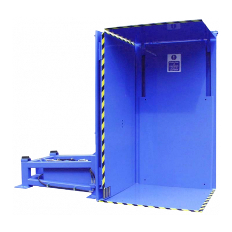
Payne Si User manual

OPERATORS MANUAL
Dereham Road, Beeston, Kings Lynn, Norfolk PE32 2NQ, UK
Telephone: +44 (0) 1328 700138 Fax: +44 (0) 1328 701879
www.paynepallenverters.co.uk
Si PALLET INVERTER
MACHINE No. x
SOLENOID CONTROL WITH FULL GUARDS

2
CONTENTS
INTRODUCTION
CONTENTS 2
CONTENTS CONTINUED 3
SAFETY PRECAUTIONS 4
PRODUCT DESCRIPTION 5
INSTALLATION
HANDLING 6
MACHINE INSTALLATION 7
GUARD INSTALLATION 8
GUARD INSTALLATION CONTINUED 9
CABLE INSTALLATION 10
GUARD INSTALLATION CONTINUED 11
CONNECTION 12
OPERATION
PRE-USE & START UP PROCEDURE 14
OPERATORS MANUAL 15
MAINTENANCE
MAINTENANCE SCHEDULE 16
LUBRICATION - GREASING WEAR PLATE 17
LUBRICATION - COMBINATION BEARINGS 18
LUBRICATION - GREASING BOSS AND PINION 19
OIL CHANGE PROCEDURE 20
OIL CHANGE PROCEDURE CONTINUED 21
TECHNICAL
LIGHT BARRIER 22
LIMIT SWITCHES 23

3
COMPONENTS
PUMP ASSEMBLY 24
PUMP ASSEMBLY (INTERNAL) 25
TURNOVER RAM 26
RACK & PINION 27
VALVE ASSEMBLY 28
CLAMP RAMS 29
BUFFERS 30
COBINATION BEARINGS 31
SPECIFICATIONS
SPECIFICATION 33
OIL DATA SHEET 34
OIL DATA SHEET CONTINUED 35
GREASE DATA SHEET 36
GREASE DATA SHEET CONTINUED 37
ATTACHED DOCUMENTS
DRAWINGS, EC CONFORMITY,
CONTENTS
CONTINUED

4
SAFETY PRECAUTIONS
SAFETY: THE MACHINE IS TO BE USED ONLY IN ACCORDANCE WITH SAFETY GUIDELINES AND IS
NOT TO BE USED FOR ANY OTHER PURPOSE THAN ORIGINALLY INTENDED.
The machine is ed with a stop buon, which MUST be acvated in all possible emergency
situaons, disabling the machine.
The following guidelines MUST be obeyed and the machine operated in strict accordance with
the operators manual:
• Only fully authorised personnel may operate this machine.
• The machine MUST only be operated when the area within the xed guards is clear.
Nobody may enter this area with the machine in operaon.
• The machine MUST only be operated within the maximum load capacity for which it was
designed (see specicaon page).
• All machine inspecon covers must be in place before use.
• All loads MUST be located securely in the machine, with the leading comer placed against
the xed rear/side wall.
• At no point may any person/persons enter the area under the machine body.
• Only fully authorised, suitably qualied personnel may carry out maintenance operaons
on this machine.
• The electrical supply MUST be isolated and suitably locked o, when carrying out any
maintenance task.
• When carrying out maintenance on or near the machine body, suitable chocks must be
placed to prevent the body from moving.
• Do NOT tamper with or alter the machine in any way.
• Correct personal protecve and safety equipment MUST be used at all mes and in
accordance with government health and safety and site specic guidelines.

5
PRODUCT DESCRIPTION
SOLENOID CONTROL & FULL GUARDS
This Pallet Inverter is a highly
versale machine, used for ecient
exchanging of pallets from a load.
The machine is loaded with a forkli
truck. A single table clamps the
load, the machine then inverts the
load through 180 degrees. This
enables the operator to easily
exchange or adjust the original
pallet. The load is then returned to
its original orientaon and removed
from the machine.
The machine is ed with a unique idencaon plate. On
this plate is stamped the model type, machine serial number,
year of manufacture and maximum permissible machine
load. This informaon should be quoted in every
communicaon with us, enabling us to deal with your
queries as eecvely as possible.
The control panel is of solenoid push buon construcon and is located
on the safety guard. This ensures the machine is operated easily and
from a posion of safety. The machine is also ed with pedestrian
access light barriers as standard.
NOTE: THE MACHINE SHOULD NOT BE USED FOR ANY OTHER PURPOSE
THAN ORIGINALLY INTENDED.

6
HANDLING
The machine MUST only be unloaded and loaded with the use of a suitably rated fork li truck
and a competent, qualied driver.
There are two fork ne receiving slots on the machine ‘A’ frame. If required a designated
lookout person should be assigned if the drivers visibility is reduced by the load. Ensure the
forkli nes are completely through the receiving slots before liing the machine.
SAFETY: CARE MUST BE TAKEN WHILST MANOEUVRING THE EQUIPMENT AROUND OBJECTS
AND PEOPLE TO AVOID DAMAGE/INJURY.
FORK TINE SLOTS

7
MACHINE INSTALLATION
Before installaon, ensure the following items are available:
• Suitably rated forkli
• Level ooring
Also ensure the presence of:
• A qualied electrician
• A qualied forkli driver
• Suitable oor space for the machine
• Correct electrical supply
NOTE: AT THIS POINT THE FLOOR SHOULD BE CHECKED TO A DEPTH OF AT LEAST 200mm FOR
UNDERGROUND OBSTRUCTIONS, WHICH COULD HINDER INSTALLATION.
• Ensure the oor is free of obstrucons or debris which
could hinder the placement of the machine.
• Place the machine in its nal intended posion, ensuring
there is enough space to access the electrical panel door
at the rear of the machine and space at the front of the
machine for placement of the guarded area.
• With the machine located, use a suitable drill and 20mm
drill bit to drill the oor at each of the 4 oor aachment
points of the frame to a depth of 100mm.
• Using a mallet, locate the supplied M20 oor anchor
bolts securely in place. Using a 30mm spanner or
ratchet, secure the machine to the oor bolts using the
appropriate supplied fasteners.
Tools Required: Fasteners (supplied):
10mm spanner Fixing kit for the machine
13mm spanner M8 Through oor bolts
19mm spanner M20 Through oor bolts
30mm spanner Machine guards
Suitable mallet Light barriers
8mm/20mm SDS drill bits
ATTACHMENT POINTS

8
GUARD INSTALLATION
• Once the Inverter is correctly bolted to the oor. Place the control box to
the front of the machine where it cannot get damaged.
• Lay out the panels and posts as the layout drawing in the back of this
manual with all the two holes on the feet on the outside of the guarded area.
Ensure that any cable are not in a position to get damaged.
NOTE: ENSURE THE GUARDS ARE IN THE CORRECT ORIENTATION BEFORE
COMMENCING ASSEMBLY.
• Start the guard assembly either side at the rear of the machine the upright posts are
already aached to the machine so the rst small back panel are bolted to the posts.
Loosely assessable the rest guard unl they are self standing and are in roughly the correct
posion. Further .
NOTE: DO NOT TIGHTEN THE GUARD PANELS
DOWN AT THIS POINT.
• Then t the cable trays to the guards (this will help
with alignment).
• Fix the L bracket to the boom of the guards, (3 on
each side, 2 on each side of the back guards). Fix the L
bracket with M6 x 20 blots so the square washer
touches the boom of the guard.
• Place the cable tray on the L bracket and loosely
fasten to the L bracket check the alignment and then
ghten the tray to the bracket.
L bracket bolt assembly
Electrical L brackets
Square washer touching
boom of guard

9
GUARD INSTALLATION
CONTINUED
• Place the cable tray corners in the back to
corners and fasten to the cable tray.
• Then x the control panel in the control box
recess by removing the boom of the control
box, xing the Panel to the Box and replacing the
boom of the box. Lay the cable in the cable tray
but do not cable e unl the guards are bolted to
the oor.
• Fix the light barrier brackets to both front guards
using M8 x 55 bolts, make sure the bracket are the correct way up and the with the ‘T’ at
the top. The light barriers need be on the central posion on they brackets. The light
barrier cables are rolled up on both side
of the machine at the boom of the
‘A’ frame legs. From the front of the
machine on the le hand side there is
two cables (one extra for the control
panel) and on the right hand side there is
one cable. Lay them loosely in the cable
tray and connect then to the boom of
light barriers.
• Once the machine is connected to the
power supply, check the alignment of the
light barriers, adjust guards if needed.
• Check the guard are in the correct
posions lock o the power to the
machine. Tighten all the guards, mark out
the guard oor holes to be drilled. And
remove the light barrier and but in a safe
place.
• Once the guards and light barriers are in
the correct posion drill the oor for
each aachment posion of the guard
feet (8mm x 100mm in depth). Locate
the M8 oor bolts for the xed guarding
securely into the ground. Once the
guards are aligned, ghten all guard
panel fasteners (once the holes are marked the cable tray can be removed to help with
access and replaced when guards are bolted to the oor).
Control
Panel
Box
Light
barrier
on
Bracket
Light
barrier
Bracket
Cable
tray

10
CABLE INSTALLATION
LIGHT BARRIER/CONTROL PANEL
• Once the machine and guards are bolted to the oor replace the light barriers, lay the
cables in the tray. Then cable e them down unl you reach the front. Plug in the cable to
the light barrier (the cables can not be mixed up as the cable can only be plugged into the
correct socket). Roll up the extra cable an cable e the front guard (see picture below).
• From the le hand side lay the cables in the cable tray and cable e it down unl you reach
the front. Plug in the cable to the light barrier. Roll up the extra cable an cable e the side
guard (see picture below).
• Unlock the power supply, check the alignment of the light barriers, adjust them with the
adjustment bolts if needed. (see page 22)
Light Hand side front Right Hand side front

11
GUARD INSTALLATION
CONTINUED

12
CONNECTION
SAFETY: THE FOLLOWING SHOULD ONLY BE CARRIED OUT BY A FULLY QUALIFIED ELECTRICIAN.
• Connect the machine to an adjacent suitably rated electrical supply.
• Ensure the stop buon on the control panel is released.
• Switch the electrical isolator on, at the main electrical panel.
• Check the guards for correct alignment and funconality.
• Press the START Buon on the control panel, this will start the pump.
• Check for the correct clockwise rotaon of the motor. If necessary, change the motor
connecons to reverse the polarity.
Isolaon Panel

13

14
PRE-USE INSPECTION
Pre-use Inspecon:
• Visually inspect the machine for any obvious deformies or irregularies.
• Ensure there are no oil leaks and the hydraulic oil level is correct on the tank sight glass.
• Ensure the area under the rotang body is free from debris using a long handled broom,
never enter the area under the rotang body at any me.
• Ensure any load placed in the machine is correctly located, with the load placed on the
xed table and the leading corner placed against the rotang body back/side wall.
SAFETY: NEVER START UP THE MACHINE IF ANY OF THE ABOVE CRITERIA ARE NOT MET
SAFETY: ALWAYS ENSURE THERE ARE NO PERSONS PRESENT WITHIN THE GUARDED AREA
PRIOR TO STARTING!
Start up Procedure:
• Turn the electrical isolator on (located at the back of the machine). Turn the Key to the on
posion.
• Press the Emergency stop buon and then release it, press the reset buon this will reset
the machine. If this is not done the machine will not turn, clamp or unclamp.
• Press the START buon, unl the light barriers reset and the pump motor runs.
• Conrm that the motor stops when the top most beam on the light barrier is physically
interrupted.
• Conrm when all remaining beams are broken, that the motor again stops.
• Check the clamping operaon of the machine, by pressing the clamp and unclamp buons
at the control panel.
• Check the machine inverts and returns when the corresponding buons are pressed at the
machine control panel.
• Check funconality of the stop buon.
• Follow the operang instrucons given on the following page.

15
OPERATORS MANUAL
Correctly locate the desired load to be inverted, with the load placed on the xed table and the
leading corner placed against the rotang body back/side wall.
SAFETY: ALWAYS ENSURE THERE ARE NO PERSONS PRESENT WITHIN THE GUARDED AREA
PRIOR TO STARTING!
Turn the key to the on posion. Press the Emergency stop buon and then release it, press the
reset buon this will reset the machine. If this is not done the machine will not turn, clamp or
unclamp.
Press the START buon, unl the light barriers reset and the pump motor runs.
Turn and Hold the CLAMP switch unl the load is fully clamped. Stop Buon
Turn and Hold the INVERT switch unl the load is fully inverted.
Turn and Hold the UNCLAMP switch unl the clamp
tables are fully opened.
Replace the original pallet from the load. Ensure the
guarded area is free from all personnel and foreign objects
before proceeding to the next steps.
Turn and Hold the CLAMP buon unl the load is
fully clamped.
Turn and Hold the RETURN buon unl the load is
fully inverted.
Turn and Hold the UNCLAMP buon unl the clamp
tables are fully open.
Remove the load from the machine. Shut down and isolate
the machine when not in use.
If the machine is stopped by light barriers beams
being broken or emergency stop buon. Check the
emergency is released and then press the reset
buon followed by the start buon to connue.
Emergency stop buon

16
MAINTENANCE SCHEDULE
SAFETY: BEFORE CARRYING OUT ANY MAINTENANCE OPERATION ENSURE THE MACHINE IS IN
ITS DEFAULT (AT REST) POSITION AND THAT THE ELECTRICAL ISOLATOR ON THE MAIN
CONTROL PANEL IS SWITCHED OFF AND LOCKED. CHOCK THE MACHINE IF WORKING IN THE
AREA OF THE ROTATING BODY.
Weekly:
• Check all lubricaon points & grease if required, including,
i. Wear plate (Page 17)
ii. Combinaon Bearings (Page 18)
iii. Pivot boss (Page 19)
Monthly:
• Check the hydraulic oil level at the tank sight glass, replenish with correct grade oil if
necessary (See specicaons page)
Bi-Annually:
• Visually examine the machine for obvious deformies, paying parcular aenon to:
i. Frame, body and tables (cracks and deformaon)
ii. Hoses, valves and manifolds (leaks or perishing)
iii. Electrical panel, including latches and hinges
iv. Electrical cables, insulaon, conduit and clamps
v. Rubber buers (wear and perishing)
vi. Light barriers (if present)
• Ensure all guard panels are secure and free from damage
• Clean the motor casing and ns
• Renew the hydraulic oil and sucon lter (see pages 20 & 21)
• Adjust the wear plate (see page 17)
SAFETY: IN THE UNLIKELY EVENT OF ANY MACHINE MALFUNCTION, STOP
AND REPORT IMMEDIATELY.
SAFETY: REPLACE ALL GUARD PANELS REMOVED DURING ANY MAINTENANCE OPERATIONS &
ENSURE ALL SAFETY DEVICES ARE RE-INSTATED.

17
LUBRICATION
GREASING WEAR PLATE
i. The wear plate is a sacricial element which is designed to guide the rack during normal
operaon, this plate requires regular lubricaon to ensure smooth operaon.
NOTE: It is important to use the correct grade of grease (see specicaon page).
From me to me the plate may also need to be adjusted, this is detailed below and takes
any play out of the rack/wear plate assembly which may have occurred due to friconal
losses.
SAFETY: SUITABLE CHOCKS SHOULD BE PUT IN PLACE TO PREVENT THE BODY FROM
MOVING WHILST LUBRICATION OF THE MACHINE IS CARRIED OUT.
REAR INSPECTION COVER
Adjusng plate for wear:
Remove inspecon cover which once removed you can gain visual access to the rack/wear plate
assembly. The wear plate can be adjusted by loosening the lock nuts and then ghtening the
adjuster screws unl the plate rests against the rack. It is important not to over ghten the wear
plate as this will induce excessive fricon in the assembly. Once correctly adjusted, re-ghten the
lock nuts and ret the rear inspecon cover.
NOTE: This procedure only needs only be carried out when the plate has worn suciently
enough for play to present itself in the assembly.
WEAR PLATE ADJUSTERS

18
LUBRICATION
COMBINATION BEARINGS
This machine is ed with precision Combinaon bearings, these bearings come
pre lubricated and do not require greasing. However it is worth checking the condion of
the bearings in accordance with the maintenance schedule and if required lightly grease.
SAFETY: SUITABLE CHOCKS SHOULD BE PUT IN PLACE TO PREVENT THE BODY FROM MOVING,
WHILST LUBRICATION OF THE MACHINE IS CARRIED OUT.
SAFETY: DISPOSE OF WASTE OIL AND SOILED RAGS CORRECTLY AND IN ACCORDANCE WITH
LOCAL AUTHORITY GUIDELINES.

19
LUBRICATION
GREASING BOSS & PINION
iii. The pivot boss houses the main pivot pin and related bush, aached to the pivot pin is the
pinion. This pinion is connected to the rack/turnover ram and is used to turn the rotang
body. This assembly is housed behind the rear cover, however there is no need to remove
this for the purpose of lubricaon.
• Lubricaon point A is for the pivot boss/bush
• Lubricaon point B is for greasing the pinion
NOTE: It is important to use the correct grade of grease (see specicaon page).
SAFETY: DISPOSE OF WASTE GREASE AND SOILED RAGS CORRECTLY AND IN ACCORDANCE
WITH LOCAL AUTHORITY GUIDELINES.
B
A

20
OIL CHANGE PROCEDURE
NOTE: ALTHOUGH THE WHOLE HYDRAULIC SYSTEM CONTAINS 60 LITRES OF OIL ONLY
40 LITRES WILL BE IN THE TANK ITSELF.
• Place a suitable empty container, sucient to hold approx. 60 litres of oil.
• Using a 24mm spanner or ratchet, unscrew the top of the return lter and carefully remove
the lter element.
• Remove the oil from the tank into the container through the return lter socket, using a
suitable oil transfer pump. Into a suitable container approximately 60 litres capacity.
• Renew the lter element and ret the top of the return lter.
• Remove the M8 screws from the tank top lid and li o carefully. The strainer lter will be
found aached to the pump assembly.
• Remove the strainer lter by turning it an-clockwise.
Tools Required: Materials Required: Part No.
13mm spanner Oil sucon lter H-F-SE1320
24mm spanner Return lter element H-F-2012
Oil transfer pump Qualube HM 32 A/R
60 litre container Oil absorbent pads A/R
Table of contents
Other Payne Lifting System manuals
Popular Lifting System manuals by other brands

NIFTYLIFT
NIFTYLIFT SD210 Series Operating/safety instructions

Limora
Limora 492893 Instruction to use

AMF
AMF 90XLi manual

Leggett & Platt
Leggett & Platt Adjustable Base Setup guide

OMCN
OMCN 126/B INSTRUCTIONS FOR USE, MAINTENANCE AND SPARE PARTS

ATD Tools
ATD Tools ATD-7489 Operating instructions & parts manual

Fenix
Fenix ELV-230/5 instructions

MIGAL.CO
MIGAL.CO ULR-3 operating manual

ALADDIN LIGHT LIFT
ALADDIN LIGHT LIFT ALL300 installation instructions

FIPA
FIPA FIPALIFT Smart Series Operating and maintenance instructions

HIAB
HIAB Hooklift Multilift XR S Series User and maintenance manual

SMC Networks
SMC Networks ZXP7 11-X1 Series Operation manual