PB International UFK Series User manual

Management Concept
With installation- and operating instructions
UFK / UFW series
Suitable for all types UFK/UFW
English
40053
PB International BV
Stikkenweg 50
7021 BN, Zelhem
Netherlands
www.pb-international.nl
1. Introduction
1.1. Guide typical symbols
IMPORTANT!
Failure to follow this instruction may risk in material damage and/or injuries.
PAY ATTENTION!
With non-compliance of the instructions there is a serious risk of damage to the
material, increased risks in equipment malfunctions and risks to the public
health.
1.2. Abbreviations and terms
▪Downstream installation: drinking water system of the building or object following
the UFK/UFW.
1.3. Liability of the manufacturer
Our products are manufactured with the utmost care. We continually look for ways to
improve our quality. Therefor we reserve the right to alter the specifications referred to in
this document.
In the following cases, we as the manufacturer are not liable:
▪Failure to observe the instructions of the device.
▪Faulty or insufficient maintenance on the equipment.
▪Failure to observe the installation instructions of the device
1.4. Responsibility of the installer/contractor
The installer is responsible for the installation and commissioning of the unit. The installer
must observe the following instructions:
▪Read this management concept and these installation and operating instructions
carefully before installing the product.
▪Preserve the installation and operating instructions for future references if needed.
These should be readily available during the lifetime of the product.
We recommend that you keep the installation and operating instruction in the immediate
environment of the product.
▪Install the product in accordance with applicable legislation and standards.
▪After commissioning, carry out all the necessary checks.
▪Explain the product to the end-user.
▪Explain the end-user the importance of maintenance on the product.
▪Hand this management concept to the end-user.
!
!
!

1.5. Disclaimer
To ensure proper functioning of the installation, the given installation- and operating
instructions must be scrupulously observed. Application and/or use of the product in a
way differentiating from its purpose is not allowed. If any damage occurs by misuse of the
installation the supplier and/or manufacturer may not be held liable.
In addition to the legal requirements and guidelines, the guidelines mentioned in the
guide are also to be adhered. For all regulations and guidelines, as mentioned in this
manual, any subsequent regulations and guidelines enabled after the date of installation
are to be adhered to as such.
1.6. Version
Version: V3.2
Year of issue: 2021
1.7. Factory Test
Each product is extensively tested before leaving the factory, including;
▪Electrical operation
▪Product integrity
▪Parameter setting
If you notice any defects please contact your supplier.
1.8. Safety
In the case of leakage occurs outside the equipment:
▪Turn off the water supply
▪Dis-connect the electrical power of the equipment
▪Try to remedy the leak.
In the case of leakage occurs inside the equipment
▪Turn off the water supply
▪Dis-connect the electrical power of the equipment
▪Contact the supplier and follow the instructions
Ensure when work is taking place, that the power supply and water pressure are shut
down to be able to work safe and freely.
!
1.9. Recommendations
The installation of the equipment must be performed by a qualified plumber according to
the assembly instructions in this document.
The equipment must be (highly preferred) installed at room temperature.
▪Check the entire system for leaks after installation.
▪Clamping parts and covers may only be removed for installation. Place these
items back in their proper place after installation.
▪Certification, serial and any other indications stickers may not be removed or
covered and must retain legible during the entire lifetime of the equipment. In
case of a damaged or illegible indication sticker immediately contact the
supplier.
▪All piping after the installation must contain flowing water, at least weekly, to
ensure the quality of water.
▪To ensure water quality through the filter with the supply of hard water a water
softener should be installed. A general guideline to determine the usability of the
water when the water contains hardness above 10 ° DH a water softener should
be placed before the filter.
▪In case a pressure boosting system is placed it should be placed in the feedline to
the ultra-filtration equipment. Exceptions can be made in consultation with the
supplier.
Changes to the equipment should only be performed after written consent by PB
International BV.
2. Preparations
Before the equipment is put into use, the following preparations must be made on the
downstream installation:
▪The downstream installation must be cleaned and disinfected after installation of the
equipment.
▪The drain has to be connected with an air gap
▪There should be a power socket within 2 meters (6 feet) of the device.
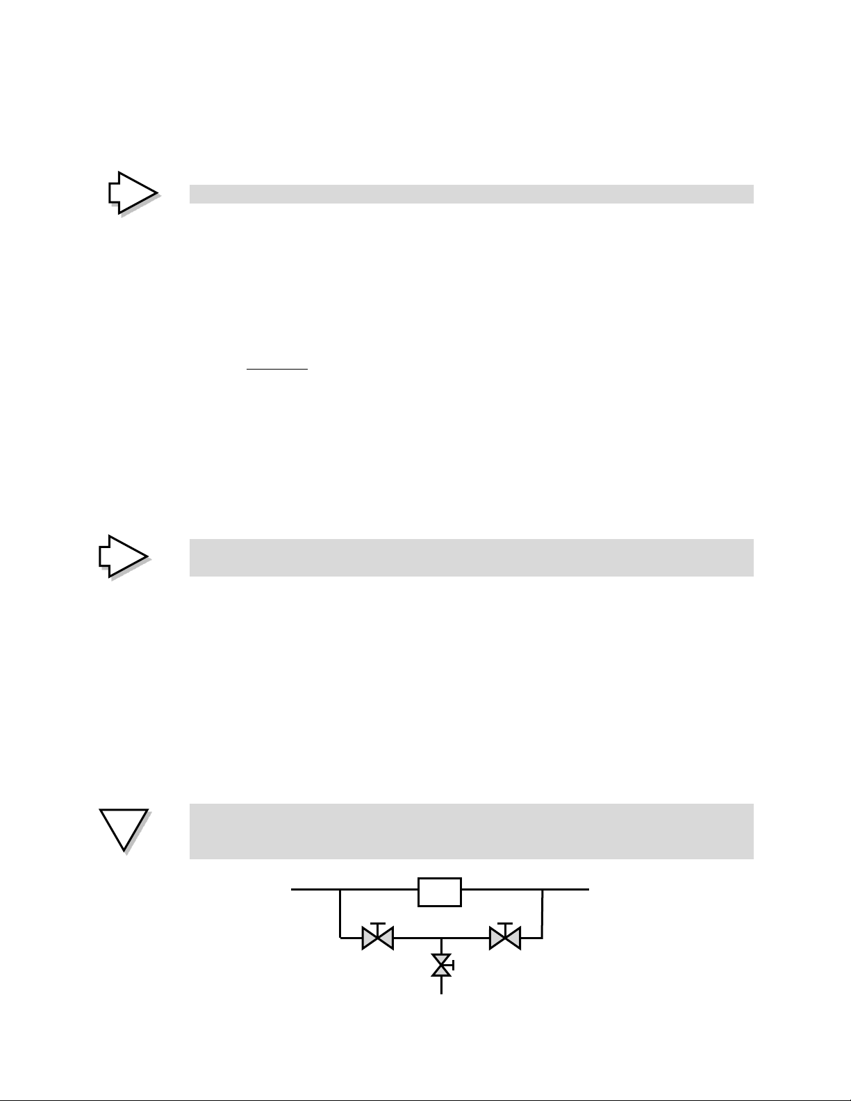
▪The construction of a bypass system is not desired. If a bypass will be installed for
well-considered reasons, this should be taken into account prior to installation.
The bypass is closed and sealed, preferably by means of a “block-and-bleed” principle,
and should not be opened under any circumstance without the written consent by PB
International (see illustration below)
!
!
!
Closed sealed
(Block)
Closed Sealed
(Block)
Drainage system
(Bleed)
UF filter module

3. Application Conditions
▪The equipment must be applied to the main water line of an installation or to a supply
line of a part of the installation.
▪The feed water must be of drinking water quality.
▪After assembly the equipment a complete cleaning and disinfection of the equipment
and the whole downstream installation is required to create a hygienic baseline.
Include a copy of the sampling results in the management concept.
▪The cleaning of the equipment should be done in consultation with the manufacturer.
▪Connecting the cleaning system of the drinking water installation should be with a
back flow protector in the feed line.
▪Dead ends must be removed before the baseline cleaning, preferably with concealed
“smooth” piping which is not capped. Changes in the distribution system should be
recorded in the logbook.
Note: Please contact your supplier if there are any questions about the application of
specific resources.
▪The management of the equipment should be properly carried out and recorded in
the log list.
4. Technical Description
4.1. General Description
The device is bearing the product name “UFK” or “UFW”. Both of these sets are based
upon ultrafiltration, intended to keep the downstream drinking water installation bacteria
and/or particle safe. The difference between both systems is in the maximum
temperature of the filter modules. The construction of the products is similar.
The product is designed for application in the main supply pipe or a part of the
installation. The purpose of the equipment is to supply the drinking water network
downstream of bacteria and/or particle safe water.
The intended use of the product entails as described in this manual, making further
contact with the product not necessary. The product should be used only if all parts are
present and assembled and if the maximum supply pressure is lower than 6 bar (~88 PSI),
with a maximum water temperature as indicated in the product specification.
4.2. Product features
Ultrafiltration
Ultrafiltration is a technique used to filter small undissolved particles, such as bacteria out
of the water supply. Ultrafiltration is a membrane based technique. The inside of the
membrane acts as a very fine sieve, with a pore size of 0.015 to 0.03 micrometres (~0.6 to
!

1.2 micro inch). The water has to be pressed through the pores with a pressure of at least
1 bar (~14.5 PSI). The reduction of the bacteria by this technique is 99.99999% (log 6).
Forward flush
This product is equipped with an automatic forward flush function. During this stage all
bacteria that remain trapped in the membranes are rinsed into the sewer.
Filtration
Forward flush

4.3. Main components
1. Digital timer
2. Flush valve spool
3. Connector clearance
4. ½” BSP 3-way coupling
5. Power cord
6. Manometer
7. Pipe clamp
8. 1” BSP 3-way coupling
9. 1” ball valve with drain
10. Filter module UFKM / UFWM
11. Prefilter 200 micron (~7900 microinch)
12. Nonreturn valve
Flushable prefilter
Carbolyxic-, or
cartridgefilter
Manual Flush Valve
4.4. Operating principle
The operating principle of the product is ultrafiltration, where the upstream water supply
is separated by a physical barrier of the downstream water (downstream installation). All
particles in water greater than 0.03 μm (~1.2 µin) remain in the filter. The bacterium safe
water (permeate) is supplied to the drinking water system. The captured particles are
automatically washed away to the drain.
4.5. Technical Specifics
General Specifics
UFK
UFW
Connections
See filter module for specifics
Flush connection
½” BSP female threaded.
Capacity (gal/min)
See filter module for specifics
Pressure loss( bar)
0,8 (~9PSI)
Power supply
See coil for specifics
Electrical power
9W
Pore size
0,015 –0,03 micron (~0.6 to 1.2 microinch)
Max temperature
40°C (104 F)
70°C (156 F)
Material
PVC-U
PVC-C
Supply pressure min
2 bar (~29 PSI)
Medium
Drinking water
Filter module specifics
Articlenr.
Description
Supply /Permeate
Capacity at 16°C (61 F)
10021
UFK 50-510
½” BSP female threaded.
0.3 m3/h
10022
UFK 63-510
¾” BSP female threaded.
0.5 m3/h
10023
UFK 75-510
¾” BSP female threaded.
0.8 m3/h
10024
UFK 90-510
¾” BSP female threaded.
1.1 m3/h
10025
UFK 90-750
¾” BSP female threaded.
1.7 m3/h
10026
UFK 90-1000
¾” BSP female threaded.
2.2 m3/h
10027
UFK 110-750
1” BSP female threaded.
2.4 m3/h
10028
UFK 125-750
1” BSP female threaded.
3.2 m3/h
10029
UFK 140-750
1” BSP female threaded.
3.7 m3/h
10030
UFK 160-750
1” BSP female threaded.
4.0 m3/h
10031
UFK 160-1000
1” BSP female threaded.
5.0 m3/h
Articlenr.
Description
Supply/ Permeate
Capacity at 30°C (86 F)
10032
UFW 50-510
½” BSP female threaded.
0.4 m3/h
10033
UFW 63-510
¾” BSP female threaded.
0.6 m3/h
10034
UFW 75-510
¾” BSP female threaded.
0.9 m3/h
10035
UFW 90-510
¾” BSP female threaded.
1.3 m3/h
10036
UFW 90-750
¾” BSP female threaded.
2.0 m3/h
10037
UFW 90-1000
¾” BSP female threaded.
2.7 m3/h
10038
UFW 110-750
1” BSP female threaded.
2.9 m3/h
10039
UFW 160-750
1” BSP female threaded.
6.0 m3/h
10040
UFW 160-1000
1” BSP female threaded.
8.4 m3/h

5. Installation instructions
Installation work should be performed by an authorized plumber in accordance with local
and national regulations.
5.1. Package content
Delivery includes:
▪Ultra-filtration module
▪Test report
▪Supply set
▪Permeate set
▪Flush set
5.2. Guidelines
When installing the equipment please take the following guidelines into account;
▪In case of water hammer, a water hammer reducer should be placed in the conduits
to serve as protection for the filter membranes.
▪Noise nuisance created by the filter should be avoided.
▪The installation must be protected from freezing and mechanical damage.
▪Never drop the product, or any parts of it. This may damage it beyond repair.
▪Do not use the product if it is damaged. Always contact your dealer. Never try to
repair the product.
▪The filter is designed with the goal to remove bacteria and/or particles from the
water and may only be used for this purpose.
▪Thoroughly clean the filter regularly, and please contact your supplier for additional
information.
▪Avoid the drying out of the membranes, if the filter module is to be stored for a
longer period of time, the fibres will dry out which can result in permanent damage.
▪Avoid direct exposure to sunlight and UV radiation.
▪Protect against abrasive material. The abrasive material in water can result in
permanent membrane damage. Place a pre-filter with pore size of 60-100 microns
(~2400-3900 micro inch) if visible pollution has been detected.
▪Avoid sudden variation in water temperature: a thermal shock should be avoided.
▪Protect the equipment against concentrated acids and organic solvents: avoid
contact between the membranes and organic solvents, chlorinated solvents, or
concentrated acid.
▪Avoid silicone-based lubricants, chemicals and oily liquids: the silicone materials can
cause permanent blockage of the fine pores of the membrane element.
▪Transport the product carefully: The membrane element can be mechanically
damaged if they fall or collide with hard objects.
!
5.3. Placement
▪The filter should be installed so that all the water is treated in the downstream
installation.
▪The system can be placed immediately after the water meter and/or pump at the
beginning of the pipeline network, or at the beginning of a separate part of the water
line.
▪The installation must be placed in a dry and frost-free area.
▪When placing the equipment please be beware that the equipment remains
accessible for maintenance.
▪The equipment must be securely mounted, preferably on a wall. Follow the
installation instructions that can be found in this document.
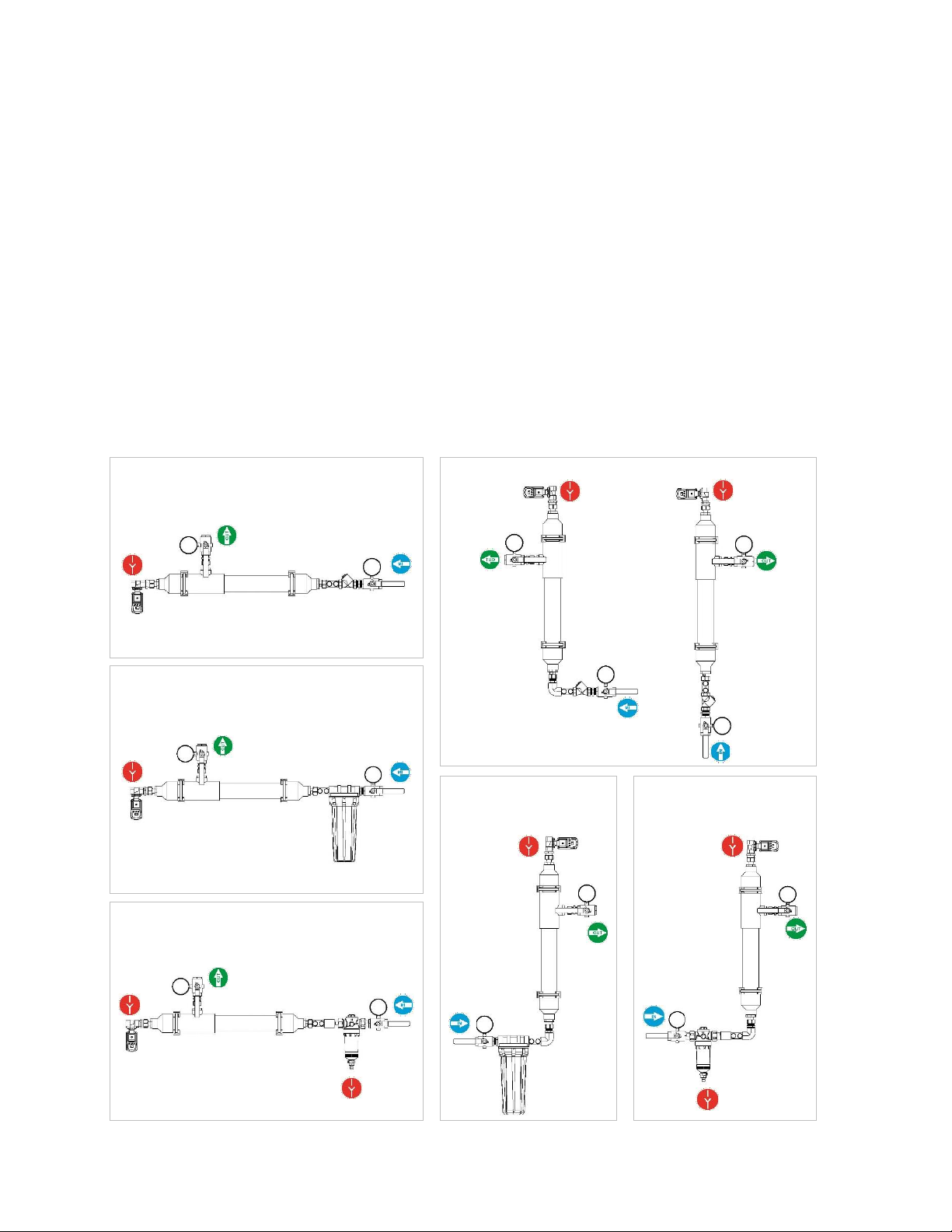
The UFK/UFW can be positioned horizontally, vertically as well as lying down. See the
images below for further reference.
Horizontal
Vertical
With a coarse pre-filter (standard)
With a coarse pre-filter (standard)
With a carbolyxic, or cartridgefilter
With a carbolyxic, or
cartridgefilter
With flushable pre-
filter
With (manual) flushable pre-filter

Note: If the equipment is mounted on a wall, please check whether the wall can support
the weight of the equipment.
5.4. Connections
▪When connecting the device please use FTP or FTPE sealing tape or sealing wire.
▪The use of hemp sealing material is not permitted due to microbial growth and
contamination.
▪The equipment connection ends are fitted with BSP thread. Please use suitable
threaded couplings with BSP threaded connection.
▪Always use the appropriate tools when working with the 6-way and 8-way connection
ends.
▪Turn the part that need tightening until they are completely tightened. Never go
further to avoid damage.
▪All pipes of the UFK/UFW should be tension freely connected to the existing network.
▪Always check whether the downstream installation is connected to the outgoing
permeate side of the equipment.
▪Always make sure the water supply is correctly connected to the inlet side of the
equipment.
Connecting the drain
▪Connect the discharge pipe with an air gap to the sewer drain; use this protection
(atmospheric interruption) according to the local instructions and guidelines.
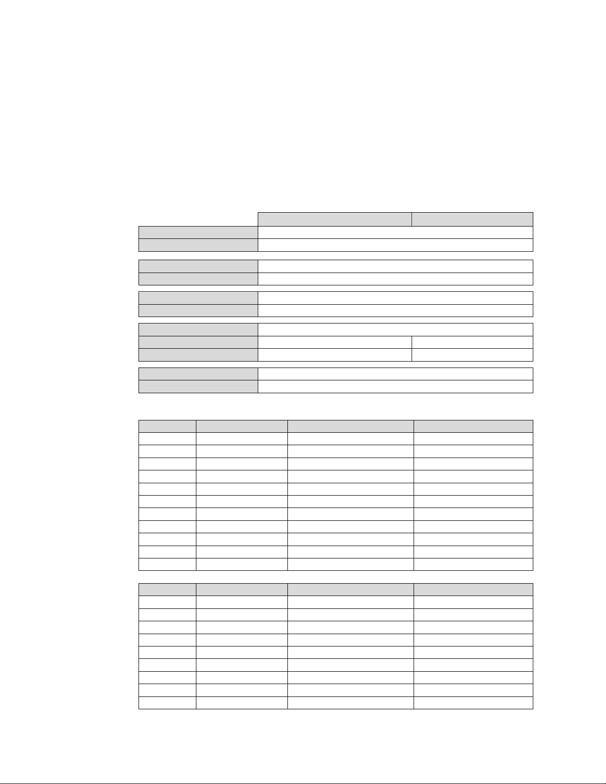
The drain line (for example, a drain) of a device must be provided with a free range
visibility according to the figure and table below.
The following requirements are placed on the drain:
▪b > G and b > 20 mm (0.8 Inch)
▪e > 4 mm (0.16 Inch)
▪G > E (The capacity from E should fit in without G reaching level 2)
▪S1+ S2+... < 1/3* b * (2 * π* G)
1
Discharge outlet
2
Overflow level
E
Discharge outlet
G
Drain
S1, S2,
etc.
Surface air inlet
b
Distance between
discharge outlet and
overflow level
e
Smallest size for
calculating air inlet
!

5.5. Assembly
1. Install the pipe clamps in the desired location.
2. Place the filter into the tube clips.
Take the items marked feed, permeate and drain.
Assemble these as shown in the examples below. Make the assembly using FTPE sealing
tape or FTPE thread sealant.
3. Install the assembled parts and then in the right place, as indicated on the filter.
4. Mount the BSP -> NPT transition couplings –if applicable –to the feed, permeate and
drain assemblies.
5.6. Installing the plug
1. Loosen the screw and remove it from the connector clearance.
2. Remove the inner part by using a small flat screwdriver.
3. Plug the power cord through the gland parts and all the way through the connector
clearance.
1.
2.
3.

Connect the stripped power cable to the screw terminals. Connect the brown wire to
terminal 1. Connect the blue wire to contact 2. Connect the yellow-green wire to
ground contact 3.
4. Press the inner part and cord back in the connector clearance. The portion may, if
necessary, be rotated in steps of 90 ° tighten the swivel parts firmly.
5.7. Electrical connections
The electrical components are not phase sensitive. The table below lists the main
characteristics of the electrical parts.
Supply voltage
See the coil
Nominal power
5W
Maximum power
9W
Degree of protection
IP65
Power supply unit
Socket outlet
The product is equipped with a plug (2 meters / 6 feet cable length) and suitable for a
power supply with live/neutral/earth connections.
2.
1.
3.
4.

6. Commissioning of the equipment
Please note that after the assembly it is important to carry out the following steps:
6.1. Checklist
▪Ensure that the voltage indicated on the appliance corresponds to the local main
voltage before you connect the appliance.
▪Check that the connections are secure.
▪Check whether the water supply is of drinking quality.
▪Ensure that the supply pressure of the water is at least 2 bar (~29PSI) and up to 6 bar
(~87PSI).
▪Check the wiring of the equipment. The plug must be well connected.
6.2. Commissioning procedure
▪Open the main valve of the drinking water system.
▪Slowly open all manual valves halfway.
▪Allow the filter to slowly fill with water.
▪Turn the manual valve fully open when the filters are completely filled.
▪Ensure that the flush lines and the drain are installed correctly.
▪Visually inspect the equipment for leaks and/or lack of water flow.
▪Plug the equipment in the grounded outlet.
Please note! The product starts immediately with the flushing and venting of the filter.
The PB filter elements contain Glycerine and sodium sulphate for conservation.
Before the appliance is fully operational it should be flushed, for at least 10 minutes, to
remove the above mentioned substances!
Turn the nearest downstream tap (from the installation) open to flush the system for at
least 10 minutes.
Carry out a complete cleaning and/or disinfecting of the equipment and the whole
downstream installation to create a hygienic baseline.
Flushing out the chemicals from the drinking water system must be done with filtered
water.
▪The disinfectant and specified flushing time are recommended by the manufacturer
and should be followed. The flushing shall be done until the presence of disinfectants
is no longer detectable.

7. Settings
7.1. Factory settings
The control of the equipment is set to an average water quality. With these settings the
device in principle will continue to function properly
Rinsing time (forward flush)
5 seconds
Rinsing frequency
4 hours
7.2. Changing settings
When the equipment is becoming clogged by an above-average contamination of the
water supply, the settings can be adjusted in consultation with the supplier. Within the
control unit all settings are interchangeable.
Product use
The changes are to be carried out with the aid of the buttons on the front side of the
control element. The table below shows the functions of the buttons:
Function F1
Function F2
< OFF
Changing flushing interval
Value -
TEST
Manual rinse
Accept change
ON >
Changing flushing time
Value +
The indicator LED’s next to the display indicate the unit’s time value.
1. Press the right button [ON>]. The display will show “ON”
2. Subsequently, the set flush time “5” is displayed on the LED display [sec].
3. With the left button the rinsing time can be shortened up until 1 second, using the
right button the rinsing time can be lengthened up until 99 hours.
4. The set rinsing time is automatically saved after 3 seconds.
1. Press the right button [<OFF]. The display will show “OFF”
2. Subsequently, the set flushing interval “4” is displayed on the LED display [hour].
3. With the left button the flushing interval can be shortened up until 1 second, using
the right button the rinsing time can be lengthened up until 99 hours.
4. The set flushing interval is automatically saved after 3 seconds.By using the [TEST]
button you can interrupt the flushing interval. After the rinsing the filter the flushing
interval will be shown.

8. Problems and Malfunctions
8.1. Detection
The table below shows the possible malfunctions with their possible causes and the
associated action.
We strongly advise you to contact PB International or your local dealer by phone before
you take any actions. Call +31 (0) 314621465. The service department can provide
support for any malfunction. This will prevent unnecessary contamination of the piping
network. Our current helpdesk number is listed in case the PB International office is
unreachable.
Detection
Possible causes
Action
No water pressure at
the taps
▪The supply pressure of
your water provider is too
low.
▪The permeate pressure is
too low (less than 0.5 bar
(~7PSI))
▪Check the supply pressure. Please
contact your water provider.
▪Place a pressure-boosting system.
Less water pressure at
the taps
▪Capacity reduction due to
pollution
▪The supply pressure is too
low (less than 1.5 bar
(~22PSI)
▪Allow a thorough cleaning to
remove all micro contamination.
▪Check the supply pressure. Please
contact your water provider.
▪A pressure-boosting system might
be advisable.
Pump in failure
▪Filter installation is
mounted BEFORE the
pump.
▪The supply pressure of
your water provider is too
low
▪Place the pump in front of the filter
installation.
▪Check the supply pressure. Please
contact your water provider.
8.2. Handling malfunctions
▪Never open the by-pass without consulting the manufacturer or an authorized party.
Opening of the by-pass interrupts the physical barrier.
▪Let the supplier repair the equipment.
If the physical bacteriological barrier fails, even shortly, the owner must assume norm
compliances of bacteria are exceeded within the downstream installation.
Take the number of water samples as prescribed in the management concept to show
possible infection.
▪Immediately after the failure of the barrier.
▪1 month after the failure of the barrier.
▪3 months after the failure of the barrier.
!

In the case of an infection restoring the hygienic baseline situation is a necessary step to
get the physical management operational again. A baseline is a hygienic bacteria
safe piping network. This should be noted by the results of <100 cfu/L (~380 cfu/gal) on
the determined number of sample points.
8.3. Actions in case of power failure
Failure of power supply has no adverse effect on the functioning of the product. There is
still safe water in the distribution system. However, the flushing function does not work
any longer.
It is important to note that the power failure is solved in a timely manner in order to
ensure the correct operation of the filters.
The installation will start flushing immediately after the power is switched on again and
no further actions are deemed necessary. When the system has been offline for more
than a week without power, please contact your supplier first.
9. Maintenance and warranty
To ensure the correct operation of the equipment it should be at least serviced annually
by a service technician authorized by the manufacturer. The following aspects should be
checked every year.
▪Cleaning and disinfection of the filter modules
▪Checking the operation of the equipment
▪Monitoring the operation and integrity of the filter modules
9.1. Warranty
The equipment has a one year manufacturer’s warranty. The warranty applies to
components. The warranty period is 1 year on material and/or workmanship. The
warranty begins on the day of delivery. Incorrect use and/or use of non-original parts will
void any warranty. In case of a defect, the manufacturer will assess the cause of the
defect. The warranty on the equipment is not applicable for contamination and defect of
the membranes by poor water supply and external factors.
9.2. Maintenance logbook
Please use the maintenance logbook on the next page to write down any malfunctions
and/or defects. The service technician must also keep track of any maintenance
performed earlier in the logbook.
!

Maintenance table
Date
Observation/Maintenance
Action
Signature
This manual suits for next models
41
Table of contents
Other PB International Water Filtration System manuals


