PBI/Gordon Broadleaf Herbicide For Turf User manual

SS1122SSEEQQUUEENNCCEERR™™
OOPPEERRAATTIINNGG
MMAANNUUAALL
1300 Midway Blvd., Mississauga, Ontario L5T 2G8
T
el. (905) 670-5888 Fax (905) 670-5782
260 North Elm Street, Westfield, MA 01085
Tel. (413) 568-9571 Fax (413) 568-9613
www.rbiwaterheaters.com
S12-IOM-1

SS1122SSeeqquueenncceerr--11--OOppeerraattiinnggIInnssttrruuccttiioonnss
Figure 1: S12 Sequencer Front Panel
IInnttrroodduuccttiioonn::
The SS1122SSeeqquueenncceerr™™is a single zone, modulation or staging boiler controller. It
provides complete control for a typical single zone 3 way valve, domestic hot water OR
heating system, including system circulators and combustion air dampers in one
single, compact package. State of the art electronic hardware and control techniques
allow for accurate, fully automatic system control while saving on operating costs.
1300 Midway Blvd., Mississauga, Ontario L5T 2G8
T
el. (905) 670-5888 Fax (905) 670-5782
260 North Elm Street, Westfield, MA 01085
Tel. (413) 568-9571 Fax (413) 568-9613
www.rbiwaterheaters.com
S12-IOM-1

SS1122SSeeqquueenncceerr--22--OOppeerraattiinnggIInnssttrruuccttiioonnss
FFuunnccttiioonn::
For heating zone applications, the SS1122SSeeqquueenncceerr™™acts as an indoor / outdoor reset
controller. It senses the OOuuttddoooorrtemperature and calculates the TTaarrggeettindoor
temperature from a reset schedule. The SS1122™™then modulates the valve or turns boiler
stages on and off, as necessary, to ensure that the IInnddoooorrtemperature reaches the
TTaarrggeetttemperature. The IInnddoooorrtemperature sensor is installed in the return water
line for staging applications, or the supply water line for modulating valve applications.
The OOuuttddoooorrtemperature sensor is located on a north wall, away from any influence
of the sun or any other heat source.
For domestic hot water applications, the SS1122™™acts as a constant temperature
controller. The TTaarrggeettindoor temperature remains constant, set to the desired
domestic hot water tank temperature. Boiler stages are then turned on and off, as
necessary, to ensure that the IInnddoooorrtemperature reaches the TTaarrggeetttemperature. The
IInnddoooorrtemperature sensor is installed in the domestic hot water tank and the OOuuttddoooorr
temperature sensor is not used.
PPaanneellDDiissppllaayy::
The Panel Display screen of the SS1122™™consists of 5 characters. The rightmost
character is the DDiissppllaayyMMooddee.It is used to describe the current value displayed. All
temperatures and PPaarraammeetteerrss(control settings) can be displayed using the following
operating modes:
1. UUnnaatttteennddeedd((ccyycclliiccaallddiissppllaayy))mmooddee: When left unattended for a period of 1
minute, the screen reverts to a cyclical display mode showing the following:
PPaarraammeetteerrDDiissppllaayyeeddSSaammpplleeSSccrreeeennPPrreessssiinnggtthheeAAddjjuusstt
bbuuttttoonnss......
Outdoor temperature - i5 0 Changes the Target
temperature value.
Indoor temperature i64 I Changes the Target
temperature value.
Target temperature i70 = Changes the Target
temperature value.
Table 1: Unattended display mode screens.
1300 Midway Blvd., Mississauga, Ontario L5T 2G8
T
el. (905) 670-5888 Fax (905) 670-5782
260 North Elm Street, Westfield, MA 01085
Tel. (413) 568-9571 Fax (413) 568-9613
www.rbiwaterheaters.com
S12-IOM-1

SS1122SSeeqquueenncceerr--33--OOppeerraattiinnggIInnssttrruuccttiioonnss
PPaanneellDDiissppllaayy::(cont’d)
1. UUnnaatttteennddeedd((ccyycclliiccaallddiissppllaayy))mmooddee(cont’d):
If any of the Adjust buttons are pressed while any of the above temperatures are
displayed, the Panel Display immediately reverts to show the Target temperature.
As the button is pressed again, the left character of the display shows the letter “c”
(eg. c. I70 = ), indicating that further pressing of the Adjust button will “change”
the current Target temperature. As the button is pressed again, the Target
temperature is changed up or down, depending on the Adjust button pressed.
WWhheenntthheecchhaannggeeiissccoommpplleettee,,tthheeDDiissppllaayyMMooddeebbuuttttoonnmmuussttbbeepprreesssseedd,,jjuussttlliikkee
aann““eenntteerr””kkeeyy,,ffoorrtthheenneewwvvaalluueettoobbeeaacccceepptteeddaasstthheenneewwTTaarrggeetttteemmppeerraattuurree..
As soon as the Display Mode button is pushed, the leading “c” disappears
(eg. I60 = ) and the Target temperature takes on the new displayed value. At this
point, the Display Panel reverts to the Manual display mode described below.
Certain overriding conditions will also affect the left-most character of the Target
temperature display as shown below. For further information, refer to the
Parameter Definitions section of this manual.
OOvveerrrriiddiinnggCCoonnddiittiioonnSSaammpplleeSSccrreeeenn
Normal Operation: Target temperature not overridden. I60 =
Target temperature in “change” mode. c. I63 =
Outdoor Cutoff Temperature: All boilers are off / valve closed. o. 73 =
High Temperature Limit: Target temperature will not exceed
this value. H. 200 =
Low Temperature Limit: Target temperature will not go below
this value. L. I05 =
Table 2: Target temperature display variations.
1300 Midway Blvd., Mississauga, Ontario L5T 2G8
T
el. (905) 670-5888 Fax (905) 670-5782
260 North Elm Street, Westfield, MA 01085
Tel. (413) 568-9571 Fax (413) 568-9613
www.rbiwaterheaters.com
S12-IOM-1

SS1122SSeeqquueenncceerr--44--OOppeerraattiinnggIInnssttrruuccttiioonnss
PPaanneellDDiissppllaayy::(cont’d)
2. MMaannuuaallddiissppllaayymmooddee: By sequentially depressing the DDiissppllaayyMMooddeebutton, the
following can be displayed in a cyclic fashion:
PPaarraammeetteerrDDiissppllaayyeeddSSaammpplleeSSccrreeeennPPrreessssiinnggtthheeAAddjjuusstt
bbuuttttoonnss......
Outdoor temperature - i5 0 Has no effect.
Indoor temperature i64 I Has no effect.
Target temperature i70 = Changes the Target
temperature value.
Remaining Hours until
Lead Boiler change h. 40 rHas no effect.
One of the control Parameter
screens (see list below) d. I00 P Displays previous or next
Parameter.
Table 3: Manual display mode screens.
Pressing the Adjust buttons while the Target temperature is displayed, changes the
Target temperature value as described in the Unattended (cyclical display) mode
above.
3. PPaarraammeetteerrddiissppllaayy//eeddiittmmooddee: Pressing the Adjust buttons1while the Parameter
screen is displayed, places the Panel Display in Parameter display mode. In this
mode, the first (left most) 2 characters of the screen describe the parameter being
displayed. The Adjust buttons are used to view the various different Parameters.
As the Up Adjust button is pressed, the next Parameter (down the table) is
displayed; as the Down Adjust button is pressed, the previous Parameter (up the
table) is displayed. Note that this display is not cyclical, ie. when the first
Parameter is displayed, pressing the Down Adjust button will not have any effect.
A summary of all Parameters follows.
1{Note: If the S12 is equipped with the KEY option, then the S12 KEY needs to be inserted (refer to Fig.
2) in order for the Adjust buttons to function. Without the KEY, the Display Mode button can still be
used to view the control’s operating temperatures, however, no control setting changes are allowed}.
1300 Midway Blvd., Mississauga, Ontario L5T 2G8
T
el. (905) 670-5888 Fax (905) 670-5782
260 North Elm Street, Westfield, MA 01085
Tel. (413) 568-9571 Fax (413) 568-9613
www.rbiwaterheaters.com
S12-IOM-1

SS1122SSeeqquueenncceerr--55--OOppeerraattiinnggIInnssttrruuccttiioonnss
PPaanneellDDiissppllaayy::(cont’d)
3. PPaarraammeetteerrddiissppllaayy//eeddiittmmooddee(cont’d):
SSttaaggiinnggPPaarraammeetteerrAAddjjuussttLLiimmiittssSSaammpplleeSSccrreeeenn
Lead boiler 1 to (number of boilers) lb. i P
Day Set point -35 to 220Fd. i00 P
Night Set point -35 to 220Fn. 90 P
Ratio - Indoor 0 to 15 ri. 1 P
Ratio - Outdoor 1 to 15 ro. 1 P
Low limit of Target temperature -34F to (High limit - 1) L. I20 P
High limit of Target temperature (Low limit + 1) to 220FH. 200 P
Outdoor Cutoff temperature 32 to 99Foc. 65 P
Outdoor Cutoff deadband 0 to 15Fod. 5 P
Throttling degrees between stages 0 to 15FSO. 5 P
Deadband between stages 0 to (Throttling - 1)Fdb. 3 P
Number of boilers (stages) 1 to 12 nb. 8 P
Lead boiler change period 1 to 255 hours h. I00 P
Lead boiler auto-increment 0 to (no. of boilers -1) AI. I P
Outdoor sensor calibration Current Outdoor reading +/- 15F. O. 25 P
Indoor sensor calibration Current Indoor reading +/- 15F. I. I65 P
Display units F or COF P
Lead pump change period 0 to 255 hours c. I00 P
Number of pumps 1 to (12 - no. of boilers) nP. 2 P
Lead Pump 1 to (no. of pumps) LP. I P
Service Parameters View only RESERVED values
Table 4: Parameter Listing for staging applications.
1300 Midway Blvd., Mississauga, Ontario L5T 2G8
T
el. (905) 670-5888 Fax (905) 670-5782
260 North Elm Street, Westfield, MA 01085
Tel. (413) 568-9571 Fax (413) 568-9613
www.rbiwaterheaters.com
S12-IOM-1

SS1122SSeeqquueenncceerr--66--OOppeerraattiinnggIInnssttrruuccttiioonnss
PPaanneellDDiissppllaayy::(cont’d)
3. PPaarraammeetteerrddiissppllaayy//eeddiittmmooddee(cont’d):
To change the value of any Parameter, using the Adjust buttons, display the desired
parameter on the Panel Display. Press the Display Mode button once - the letter
“P” (the rightmost character of the screen) will start flashing1. Use the Adjust
buttons to change the value of the Parameter. When the change is complete, the
Display Mode button must be pressed again, just like an “enter” key, for the new
value to be accepted as the new Parameter value. As soon as the Display Mode
button is pushed, the letter P will stop flashing. At this point, the Panel Display
automatically reverts back to Manual display mode, ie. if the Display mode button
is pressed again, the Outdoor temperature will be displayed (refer to Table 3
above).
1{Note: If this does not occur, the Panel Display is still in Manual display mode. Continue to
sequentially press the Display mode button until the Parameter screen is shown. Press the Up or
Down Adjust button to display the next or previous Parameter. At this point, the Panel Display is in
Parameter display mode. The Adjust buttons can be used to display the desired Parameter and the
Display Mode button will act as an “enter” key}.
To exit Parameter display mode and go back to Manual display mode, press the
Display mode button twice in succession.
1300 Midway Blvd., Mississauga, Ontario L5T 2G8
T
el. (905) 670-5888 Fax (905) 670-5782
260 North Elm Street, Westfield, MA 01085
Tel. (413) 568-9571 Fax (413) 568-9613
www.rbiwaterheaters.com
S12-IOM-1

SS1122SSeeqquueenncceerr--77--OOppeerraattiinnggIInnssttrruuccttiioonnss
Figure 2: S12 Wiring Diagram
1300 Midway Blvd., Mississauga, Ontario L5T 2G8
T
el. (905) 670-5888 Fax (905) 670-5782
260 North Elm Street, Westfield, MA 01085
Tel. (413) 568-9571 Fax (413) 568-9613
www.rbiwaterheaters.com
S12-IOM-1

SS1122SSeeqquueenncceerr--88--OOppeerraattiinnggIInnssttrruuccttiioonnss
PPaarraammeetteerrDDeeffiinniittiioonnss::
1. OOuuttddoooorrTTeemmppeerraattuurree::The current temperature at the sensor wired in the
“Outdoor sensor” wiring location between the “+” and “I2" terminals - refer to
wiring diagram in Figure 2. The Outdoor sensor is typically used for heating system
applications only. It should be located on a north wall, away from any heat sources
like exhaust fan hoods or mechanical room relief air openings.
2. IInnddoooorrTTeemmppeerraattuurree::The current temperature at the sensor wired in the “Indoor
sensor” wiring location between the “+” and “I1" terminals - refer to wiring
diagram in Figure 2.
a. For heating system applications, the Indoor sensor should be installed in the
return water line, ie. the water pipe coming back from the building, before it
enters the boilers.
b. For domestic hot water applications, the Indoor sensor should be located on the
domestic hot water tank, approximately one third up from the bottom.
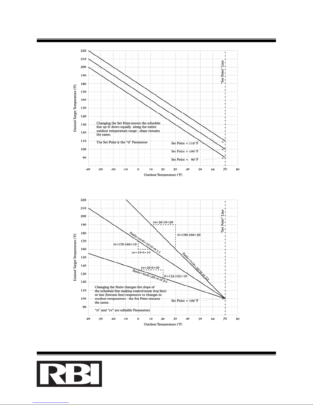
3. TTaarrggeettTTeemmppeerraattuurree: The desired temperature that the SS1122™™is attempting to
maintain the Indoor sensor temperature at.
a. For heating system applications, the Target temperature is calculated using the
Day Set Point (or Night Set Point - depending on the state of the “Night
Setback” input across terminals “I4" and “GND”), Ratio - Indoor and Ratio -
Outdoor parameter values as well as the current Outdoor temperature.
b. For domestic hot water applications, the Target temperature equals the Day Set
Point (or Night Set Point - depending on the state of the “Night Setback” input).
The Ratio parameters and Outdoor temperature are ignored.
c. Refer to Figures 3, 4 & 5 for illustration.
1300 Midway Blvd., Mississauga, Ontario L5T 2G8
T
el. (905) 670-5888 Fax (905) 670-5782
260 North Elm Street, Westfield, MA 01085
Tel. (413) 568-9571 Fax (413) 568-9613
www.rbiwaterheaters.com
S12-IOM-1
SS1122SSeeqquueenncceerr--99--OOppeerraattiinnggIInnssttrruuccttiioonnss
Figure 3: Effect on Target temperature from Set Point changes
Figure 4: Effect on Target temperature from Ratio changes
1300 Midway Blvd., Mississauga, Ontario L5T 2G8
T
el. (905) 670-5888 Fax (905) 670-5782
260 North Elm Street, Westfield, MA 01085
Tel. (413) 568-9571 Fax (413) 568-9613
www.rbiwaterheaters.com
S12-IOM-1
SS1122SSeeqquueenncceerr--1100--OOppeerraattiinnggIInnssttrruuccttiioonnss
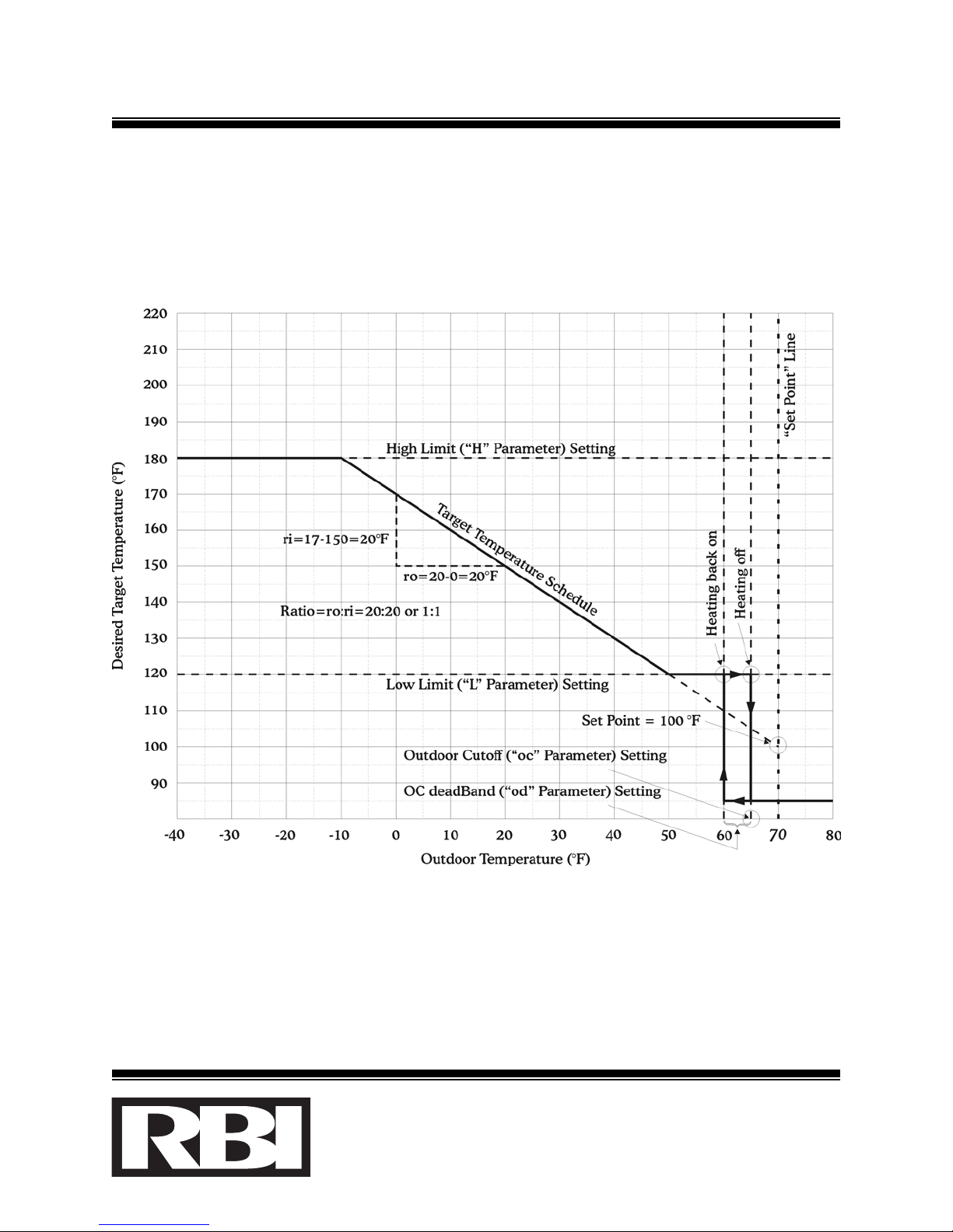
Figure 5: Target temperature graph
1300 Midway Blvd., Mississauga, Ontario L5T 2G8
T
el. (905) 670-5888 Fax (905) 670-5782
260 North Elm Street, Westfield, MA 01085
Tel. (413) 568-9571 Fax (413) 568-9613
www.rbiwaterheaters.com
S12-IOM-1

SS1122SSeeqquueenncceerr--1111--OOppeerraattiinnggIInnssttrruuccttiioonnss
SSttaaggiinnggCCoonnttrroollPPaarraammeetteerrDDeeffiinniittiioonnss::
1. LLeeaaddbbooiilleerr((““LLbb””ppaarraammeetteerr)): The desired ssttaaggeenumber to be turned on first,
when heat is required. This parameter can be used to make any of the boilers in
the system, lead boiler. The Combustion Air Damper cycles on/off with the lead
stage.
2. DDaayySSeettPPooiinntt((““dd””ppaarraammeetteerr)): The desired Target temperature when the outdoor
temperature is 70F/21C. This value is used to calculate the Target temperature
when in Day mode - ie. an open circuit at the “Night Setback” input across
terminals “I4" and “GND”). As the outdoor temperature drops from 70F/21C, the
SS1122™™will raise the Target temperature according to the Ratio - Indoor and Ratio -
Outdoor parameters. Refer to Figure 3.
3. NNiigghhttSSeettPPooiinntt((““nn””ppaarraammeetteerr)): Same as the Day Set Point. This value is used
instead of the Day Set Point when in Night mode - ie. a short circuit at the “Night
Setback” input across terminals “I4" and “GND”).
4. RRaattiioo--IInnddoooorr((““rrII””ppaarraammeetteerr)): The indoor quantity of the slope of the outdoor
reset curve calculation. This parameter is used in conjunction with the Ratio -
Outdoor parameter to describe how responsive the control is to changes in outdoor
temperature. Eg. For every “rO” degrees drop in outdoor temperature, the control
will raise the Target water temperature by “rI” degrees. Similarly, for every “rO”
degrees rise in outdoor temperature, the control will drop the Target water
temperature by “rI” degrees. For constant water applications, set “rI” to 0.
5. RRaattiioo--OOuuttddoooorr((““rrOO””ppaarraammeetteerr)): The outdoor quantity of the slope of the
outdoor reset curve calculation. Refer to the example in the “rI” parameter
definition above. Refer to Figure 4.
6. LLoowwlliimmiittooffTTaarrggeetttteemmppeerraattuurree((““LL””ppaarraammeetteerr)): The lowest value that the Target
temperature is allowed to drop to. Note that when the outdoor temperature is
sufficiently hot not to require heat (ie. Outdoor Cutoff mode), all stages will still go
off. This parameter is most useful to prevent boilers from operating below their
condensating temperatures, typically 110F/43C to 160F/71C, depending on the
boiler manufacturer. Please refer to the boiler manufacturer’s specification for the
correct low operating limit for the application. When the Target temperature low
limit is reached, an “L” appears to the left of the Target temperature value.
1300 Midway Blvd., Mississauga, Ontario L5T 2G8
T
el. (905) 670-5888 Fax (905) 670-5782
260 North Elm Street, Westfield, MA 01085
Tel. (413) 568-9571 Fax (413) 568-9613
www.rbiwaterheaters.com
S12-IOM-1

SS1122SSeeqquueenncceerr--1122--OOppeerraattiinnggIInnssttrruuccttiioonnss
SSttaaggiinnggCCoonnttrroollPPaarraammeetteerrDDeeffiinniittiioonnss::(cont’d)
7. HHiigghhlliimmiittooffTTaarrggeetttteemmppeerraattuurree((““HH””ppaarraammeetteerr)): The highest value that the
Target temperature is allowed to rise to. This parameter is most useful to
prevent boilers from operating above a desired limit, eg. prevent scalding by
limiting the domestic hot water tank temperature. When the Target
temperature high limit is reached, an “H” appears to the left of the Target
temperature value. Refer to Figure 5.
8. OOuuttddoooorrCCuuttoofffftteemmppeerraattuurree((““oocc””ppaarraammeetteerr)): The outdoor temperature limit
above which all heating is disabled. When the outdoor temperature is
sufficiently hot not to require the heating system to operate (ie. outdoor
temperature > “oc” temperature), the Main Pump(s), Combustion Air Damper
and all boiler stages are turned off. When in Outdoor Cutoff mode, an “o”
appears to the left of the Target temperature value. Refer to Figure 5.
9. OOuuttddoooorrCCuuttooffffddeeaaddbbaanndd((““oodd””ppaarraammeetteerr)): The number of degrees the
outdoor temperature has to drop below the Outdoor Cutoff temperature before
the heating is enabled. When the outdoor temperature is sufficiently cool to
require the heating system to operate (ie. outdoor temperature <= “oc” - “od”),
the Main Pump(s) are turned on and the boiler stages and Combustion Air
Damper are operated as required. When heating is enabled, no character
appears to the left of the Target temperature value.
10. TThhrroottttlliinnggddeeggrreeeessbbeettwweeeennssttaaggeess((““SS””ppaarraammeetteerr)): The number of degrees
the indoor temperature has to drop before the next heating stage is turned on.
This parameter should be set to the maximum temperature rise capability of all
the boiler stages divided by the number of stages, eg. if 4 boiler stages are able
to raise the return water temperature by 20F, then set “S” to 5.
11. DDeeaaddbbaannddbbeettwweeeennssttaaggeess((““ddbb””ppaarraammeetteerr)): The minimum number of degrees
over which the same boiler stage can be turned on and off. This parameter is
used to prevent the boiler stages from cycling on/off too rapidly. Typically, “db”
should be set to 1-3F.
1300 Midway Blvd., Mississauga, Ontario L5T 2G8
T
el. (905) 670-5888 Fax (905) 670-5782
260 North Elm Street, Westfield, MA 01085
Tel. (413) 568-9571 Fax (413) 568-9613
www.rbiwaterheaters.com
S12-IOM-1

SS1122SSeeqquueenncceerr--1133--OOppeerraattiinnggIInnssttrruuccttiioonnss
SSttaaggiinnggCCoonnttrroollPPaarraammeetteerrDDeeffiinniittiioonnss::(cont’d)
12. NNuummbbeerrooffbbooiilleerrssttaaggeess((““nnbb””ppaarraammeetteerr)): The total quantity of heating ssttaaggeess
available in the heating system. Eg. If a heating system has 4 two stage boilers,
then set “nb” to 8 (4x2).
13. LLeeaaddbbooiilleerrcchhaannggeeppeerriioodd((““hh””ppaarraammeetteerr)): The actual number of hours the
lead boiler has to operate / run before the lead is changed. This parameter is
used to operate each and every boiler as lead. This allows all boilers to take
their turn at being lead, thus providing even wear on all equipment.
14. LLeeaaddbbooiilleerraauuttoo--iinnccrreemmeenntt((““AAII””ppaarraammeetteerr)): The number of stages per boiler
in the system. When the lead boiler is changed automatically, “Lb” is
incremented by “AI” to make the next boiler lead. Eg. If a heating system has
4 two stage boilers then set “AI” to 2. In this manner, the “Lb” parameter will
sequentially make stages 1, 3, 5 and 7 lead.
15. OOuuttddoooorrsseennssoorrccaalliibbrraattiioonn((““OO””ppaarraammeetteerr)): This is the current reading of the
outdoor temperature. By using the Adjust buttons, the outdoor temperature
reading can be changed by +/- 15F.
16. IInnddoooorrsseennssoorrccaalliibbrraattiioonn((““II””ppaarraammeetteerr)): This is the current reading of the
indoor temperature. By using the Adjust buttons, the indoor temperature
reading can be changed by +/- 15F.
17. DDiissppllaayyuunniittss: This parameter serves to change the temperature units of the
Panel Display. Both F and C are supported.
18. LLeeaaddppuummppcchhaannggeeppeerriioodd((““cc””ppaarraammeetteerr)): The actual number of hours the
lead pump has to operate / run before the lead is changed. This parameter is
used to operate each and every main pump as lead. This allows all pumps to
take their turn at being lead, thus providing even wear on all equipment.
1300 Midway Blvd., Mississauga, Ontario L5T 2G8
T
el. (905) 670-5888 Fax (905) 670-5782
260 North Elm Street, Westfield, MA 01085
Tel. (413) 568-9571 Fax (413) 568-9613
www.rbiwaterheaters.com
S12-IOM-1

SS1122SSeeqquueenncceerr--1144--OOppeerraattiinnggIInnssttrruuccttiioonnss
SSttaaggiinnggCCoonnttrroollPPaarraammeetteerrDDeeffiinniittiioonnss::(cont’d)
19. NNuummbbeerrooffppuummppss((““nnPP””ppaarraammeetteerr)): The total quantity of main circulating
pumps (not individual boiler circulators) available in the heating system. Note
that the wiring diagram in Figure 2 shows two possible wiring locations for the
main pumps.
a. For systems with oonneeppuummpp, set “nP” to 1 and wire the pump using relay
terminals “1” and “1” bbeelloowwtthheetteemmppeerraattuurreesseennssoorrtteerrmmiinnaallss(not the boiler
stage “1” and “1” terminals). This configuration allows for up to 12 stages of
boiler control.
b. For systems with mmoorreetthhaannoonneeppuummpp, set “nP” to the actual number of pumps
and wire pump #1 using the boiler stage terminals “12” and “12”, wire pump
#2 using the boiler stage teminals “11” and “11”, etc.
20. LLeeaaddppuummpp((““LLPP””ppaarraammeetteerr)): The desired pump number to be turned on first,
when heat is required. This parameter can be used to make any of the pumps
in the system, lead pump.
TTrroouubblleeSShhoooottiinnggGGuuiiddee::
1. TThheeddiissppllaayyiissnnoottlliitt::
a. Check power - if 24Vac does not appear across the two terminals marked
“Power In 24Vac”, the control will not operate.
b. If power is present, however, the control still does not operate then the
controller requires service.
2. EEiitthheerrtteemmppeerraattuurreesseennssoorrrreeaaddssaavveerryylloowwtteemmppeerraattuurree((--3333ttoo--3355FF))::
a. The sensor is indicating an open circuit. Check for a break in the wire, OR,
reverse the polarity of the sensors wires (swap the black & red wires).
b. Try removing the sensor & installing it directly on the S12 terminals:
i. If the sensor reads the temperature of the room then the problem is with the
wiring of the sensor run.
ii. If the sensor does not read the temperature of the room then the problem is
the sensor itself - replace sensor.
1300 Midway Blvd., Mississauga, Ontario L5T 2G8
T
el. (905) 670-5888 Fax (905) 670-5782
260 North Elm Street, Westfield, MA 01085
Tel. (413) 568-9571 Fax (413) 568-9613
www.rbiwaterheaters.com
S12-IOM-1

SS1122SSeeqquueenncceerr--1155--OOppeerraattiinnggIInnssttrruuccttiioonnss
TTrroouubblleeSShhoooottiinnggGGuuiiddee::(cont’d)
3. EEiitthheerrtteemmppeerraattuurreesseennssoorrrreeaaddssaavveerryyhhiigghhtteemmppeerraattuurree((221188--222200FF))::
a. The sensor is indicating an short circuit. Check for a short in the wire or sensor.
b. Try removing the sensor & installing it directly on the S12 terminals:
i. If the sensor reads the temperature of the room then the problem is with the
wiring of the sensor run.
ii. If the sensor does not read the temperature of the room then the problem is
the sensor itself - replace sensor.
4. NNootteetthhaatttthheetteemmppeerraattuurreesseennssoorrssaarreennoottrreessiissttiivveeeelleemmeennttssbbuuttaarreeiinnffaaccttaarree22
wwiirreeccuurrrreennttssoouurrcceess..TThheeccuurrrreennttiinntthheesseennssoorrcciirrccuuiittvvaarriieesswwiitthhtteemmppeerraattuurreeaatt
aarraatteeooff11AA//KK..AAddiirreeccttccuurrrreennttmmeeaassuurreemmeennttccaannnnoottbbeemmaaddeedduueettootthhee
tteemmppeerraattuurreemmuullttiipplleexxiinnggnnaattuurreeoofftthheesseennssiinnggcciirrccuuiitt..IIffaammeeaassuurreemmeennttiiss
aatttteemmpptteedd,,aalloowwrreeaaddiinnggwwiillllbbeeoobbsseerrvveedd..
5. TThheewwaatteerrtteemmppeerraattuurreeddiissppllaayysshhoowwss6600yyeetttthheeaaccttuuaallwwaatteerrtteemmppeerraattuurreeffeeeellss
mmuucchhhhootttteerrtthhaann6600FF::
a. Check the temperature display units parameter. It is set to C. Note that the
temperature display units are NOT displayed with the temperature sensors
readings. For this reason, the user must know in which scale (F or C) the S12
is set.
6. TThheeSS1122ssttaaggeeiisslliittyyeetttthheebbooiilleerriissnnoottffiirriinngg::
a. First check the S12 relay. Remove the boiler wiring from both relay terminals
and check for continuity:
i. When the stage is on, there should be a short circuit across the relay
terminals.
ii. When the stage is off, there should be an open circuit across the relay
terminals.
iii. If either of the above is not found, the control requires service.
b. When the S12 relay checks out correctly then verify the boiler operation. The
boiler is either turned off or is off on a safety device (high limit, operating
aquastat, flow switch, low water cutoff, low or high gas pressure, flame failure,
low air flow, etc.). Refer to the boiler manufacturer literature on trouble
shooting the boiler.
1300 Midway Blvd., Mississauga, Ontario L5T 2G8
T
el. (905) 670-5888 Fax (905) 670-5782
260 North Elm Street, Westfield, MA 01085
Tel. (413) 568-9571 Fax (413) 568-9613
www.rbiwaterheaters.com
S12-IOM-1
Other manuals for Broadleaf Herbicide For Turf
1
Table of contents
Popular Network Router manuals by other brands


D-Link
D-Link DSL-2751 Quick installation guide

Robustel
Robustel GoFixed W800 user guide

TP-Link
TP-Link SafeStream TL-R480T+ user guide

Linksys
Linksys WET11 - Instant Wireless EN Bridge Network... Quick installation guide

D-Link
D-Link DSL-2650U Quick installation guide

Vonets
Vonets VOPWRT Configuration instructions


