PCB Piezotronics W138A01/038CY030AC User manual

Model W138A01/038CY030AC
OBSOLETE PER DIN 41403
Installation and Operating Manual
For assistance with the operation of this product,
contact the PCB Piezotronics, Inc.
Toll-free: 716-684-0001
24-hour SensorLine: 716-684-0001
Fax: 716-684-0987
E-mail: [email protected]
Web: www.pcb.com

Manual 21354 Rev E
ECN 50523
Repair and Maintenance
PCB guarantees Total Customer Satisfaction through its
“Lifetime Warranty Plus” on all Platinum Stock Products
sold by PCB and through its limited warranties on all other
PCB Stock, Standard and Special products. Due to the
sophisticated nature of our sensors and associated
instrumentation, field servicing and repair is not
recommended and, if attempted, will void the factory
warranty.
Beyond routine calibration and battery replacements
where applicable, our products require no user
maintenance. Clean electrical connectors, housings, and
mounting surfaces with solutions and techniques that will
not harm the material of construction. Observe caution
when using liquids near devices that are not hermetically
sealed. Such devices should only be wiped with a
dampened cloth—never saturated or submerged.
In the event that equipment becomes damaged or ceases
to operate, our Application Engineers are here to support
your troubleshooting efforts 24 hours a day, 7 days a
week. Call or email with model and serial number as well
as a brief description of the problem.
Calibration
Routine calibration of sensors and associated
instrumentation is necessary to maintain measurement
accuracy. We recommend calibrating on an annual basis,
after exposure to any extreme environmental influence,
or prior to any critical test.
PCB Piezotronics is an ISO-9001 certified company whose
calibration services are accredited by A2LA to ISO/IEC
17025, with full traceability to SI through N.I.S.T. In
addition to our standard calibration services, we also offer
specialized tests, including: sensitivity at elevated or
cryogenic temperatures, phase response, extended high
or low frequency response, extended range, leak testing,
hydrostatic pressure testing, and others. For more
information, contact your local PCB Piezotronics
distributor, sales representative, or factory customer
service representative.
Returning Equipment
If factory repair is required, our representatives will
provide you with a Return Material Authorization (RMA)
number, which we use to reference any information you
have already provided and expedite the repair process.
This number should be clearly marked on the outside of
all returned package(s) and on any packing list(s)
accompanying the shipment.
Contact Information
PCB Piezotronics, Inc.
3425 Walden Ave.
Depew, NY14043 USA
Toll-free: (800) 828-8840
24-hour SensorLine: (716) 684-0001
Repair inquiries: rma@pcb.com
For a complete list of distributors, global offices and sales
representatives, visit our website, www.pcb.com.
Safety Considerations
This product is intended for use by qualified personnel
who recognize shock hazards and are familiar with the
precautions required to avoid injury. While our equipment
is designed with user safety in mind, the protection
provided by the equipment may be impaired if equipment
is used in a manner not specified by this manual.
Discontinue use and contact our 24-Hour Sensorline if:
Assistance is needed to safely operate equipment
Damage is visible or suspected
Equipment fails or malfunctions
For complete equipment ratings, refer to the enclosed
specification sheet for your product.
Definition of Terms and Symbols
The following symbols may be used in this manual:
DANGER
Indicates an immediate hazardous
situation, which, if not avoided, may
result in death or serious injury.

Manual 21354 Rev E
ECN 50523
CAUTION
Refers to hazards that could damage
the instrument.
NOTE
Indicates tips, recommendations and
important information. The notes
simplify processes and contain
additional information on particular
operating steps.
The following symbols may be found on the equipment
described in this manual:
This symbol on the unit indicates that
high voltage may be present. Use
standard safety precautions to avoid
personal contact with this voltage.
This symbol on the unit indicates that
the user should refer to the operating
instructions located in the manual.
This symbol indicates safety, earth
ground.

Manual 21354 Rev E
ECN 50523
PCB工业监视和测量设备 - 中国RoHS2公布表
PCB Industrial Monitoring and Measuring Equipment - China RoHS 2 Disclosure Table
部件名称
有害物质
铅(Pb)
汞
(Hg)
镉
(Cd)
六价铬(Cr(VI))
多溴联苯 (PBB)
多溴二苯醚(PBDE)
住房
O
O
O
O
O
O
PCB板
X
O
O
O
O
O
电气连接器
O
O
O
O
O
O
压电晶体
X
O
O
O
O
O
环氧
O
O
O
O
O
O
铁氟龙
O
O
O
O
O
O
电子
O
O
O
O
O
O
厚膜基板
O
O
X
O
O
O
电线
O
O
O
O
O
O
电缆
X
O
O
O
O
O
塑料
O
O
O
O
O
O
焊接
X
O
O
O
O
O
铜合金/黄铜
X
O
O
O
O
O
本表格依据 SJ/T 11364 的规定编制。
O:表示该有害物质在该部件所有均质材料中的含量均在 GB/T 26572 规定的限量要求以下。
X:表示该有害物质至少在该部件的某一均质材料中的含量超出 GB/T 26572 规定的限量要求。
铅是欧洲RoHS指令2011/65/ EU附件三和附件四目前由于允许的豁免。
CHINA RoHS COMPLIANCE

Manual 21354 Rev E
ECN 50523
Component Name
Hazardous Substances
Lead (Pb)
Mercury (Hg)
Cadmium (Cd)
Chromium VI
Compounds
(Cr(VI))
Polybrominated
Biphenyls (PBB)
Polybrominated
Diphenyl Ethers
(PBDE)
Housing
O
O
O
O
O
O
PCB Board
X
O
O
O
O
O
Electrical Connectors
O
O
O
O
O
O
Piezoelectric Crystals
X
O
O
O
O
O
Epoxy
O
O
O
O
O
O
Teflon
O
O
O
O
O
O
Electronics
O
O
O
O
O
O
Thick Film Substrate
O
O
X
O
O
O
Wires
O
O
O
O
O
O
Cables
X
O
O
O
O
O
Plastic
O
O
O
O
O
O
Solder
X
O
O
O
O
O
Copper Alloy/Brass
X
O
O
O
O
O
This table is prepared in accordance with the provisions of SJ/T 11364.
O: Indicates that said hazardous substance contained in all of the homogeneous materials for this part is below the limit
requirement of GB/T 26572.
X: Indicates that said hazardous substance contained in at least one of the homogeneous materials for this part is above the limit
requirement of GB/T 26572.
Lead is present due to allowed exemption in Annex III or Annex IV of the European RoHS Directive 2011/65/EU.

OPERATION MANUAL FOR
1
Series 138
Series 138 Standard Length, with Lead Wire Hole for Attaching Weights
Series 138 Short Length, One-Piece Molded Closed-End Tube
1.0 INTRODUCTION
PCB Series 138 sensors are voltage mode tourmaline
sensors designed for operation underwater or in
liquids compatible with tygon and nylon. (See
specification sheet in the back of the manual for range
and sensitivity).
Series 138 features built-in ICP®amplifiers which
convert the high-impedance voltage from the crystals
into a low-impedance output voltage of less than 100
ohms. Power to operate the IC amplifier and the output
signal is conducted over a single conductor coaxial
cable with a shield serving as signal return. Special
low-noise cables are not required.
Series 138 is used by the military for underwater
explosive testing, commercial use in gasoline tanks
and transformer shock wave applications. The
sensors are ideal for monitoring dynamic pressures
because they exhibit near non-resonant response.
The charge generated by deflection of the piezoelectric
element when subjected to shock waves creates a
voltage on the input capacitance at the gate of the
amplifier. The amplifier, in conjunction with the
source element, transforms this input into a low-
impedance signal of equal amplitude. The DC bias that
exists on the signal lead is blocked from the output by
a coupling capacitor in the PCB signal conditioners.
Drawing Number: 21102
Revision: B

Drawing Number: 21102
Revision: B
OPERATION MANUAL FOR
2
Series 138
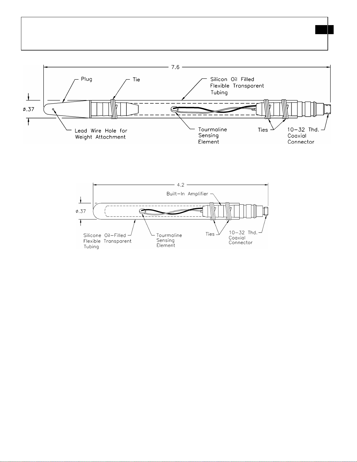
Some models of the Series 138 feature a tygon tube
closed at one end with conical-shaped delrin plug. The
plug features a small hole for attachment of a weight.
Other models feature a one-piece molded closed tube.
2.0 INSTALLATION, CABLE
ATTACHMENT, AND SEALING
THE CABLE/CONNECTOR
ASSEMBLY
Various methods are used to mount the 138 sensors for
use in liquids. Care should be taken to prevent
conductive liquids from entering the cable or
connector assemblies, where they could cause
corrosion, short-circuiting or degradation of
insulation resistance.
For low-pressure (<500psi) dynamic measurements, a
standard low-noise coaxial cable with an extruded
teflon jacket and a 10-32 connector can be used. Heat
shrink tubing, RTV silicon rubber, or sometimes
silicone grease can make an adequate seal in an
environment with low static pressure.
For high static pressures due to deep submersion or use
in a pressure vessel, alternate methods of sealing the
cable/connector may be required. A method of
waterproofing the cable/connector assembly of a 138
which also provides protection to the cable is to put a
flexible tube (plastic, tygon, etc.) around the cable
and cable/connector assembly. Tie the tube at the
metal housing with monofilament or fine steel wire.
The opposite end of the tube must be above the level
of the liquid or sealed around the cable to prevent
liquid from entering the protective tubing. Filling the
protective tube with a non-conducting liquid such as
Dow Coming silicone oil can be done to prevent the
tube from collapsing. This will also equalize pressure
inside and outside the tubing, helping to prevent a
conductive liquid (such as water) from entering.
In some blast applications, when using a standard 10-
32 micro cable/connector, the high shock can flex the
cable/connector joint enough to move the center pin of
the 10-32 cable connector. This can cause noise on
the output signal. Protecting the connection from
shock may be required.
PCB Model 070A03 adaptor can be used to adapt the
10-32 micro jack on the 138 to a BNC jack. A heavier
coaxial cable (eg. RG-58/U) can now be used in place
of the micro cable. Because of the large mass of the
070A03 compared to the 10-32 jack, this connection
should be sealed and protected from shock and
turbulence. Putting a two to three inch diameter of duct
seal, wrapped with a waterprooftape, will seal the
connection and provide shock protection at the
cable/connector/ amplifier assembly.
PCB Model 070A09 Solder Connector Adaptor can
also be used to attach a short length (~two to three
inches) of ribbon cable to a 138. The ribbon cable can
then be soldered to an extension cable. The ribbon
cable and both solder connections should be sealed
with a suitable waterproofing material. Various types
of sealing materials such as polyethylene and flexane
have been shown to be effective for sealing cables,
connectors, etc.
2.1 MOUNTING OR SUSPENDING
THE SENSOR
After the cable/connector assembly is sealed, the
sensor can be suspended in the liquid where the
measurement is to take place. For low dynamic
pressure measurements (less than 500 psi), models
featuring a small hole in the conical end piece of the
tube allow attachment of a light weight (~two lb.) to
suspend the sensor in a vertical position.
The line should be of light material (monofilament,15
lb. test) to enable it to break easily. This way, the
sensor does not pull apart in the turbulence caused by
the collapse of gas bubbles resulting from a shock
wave.
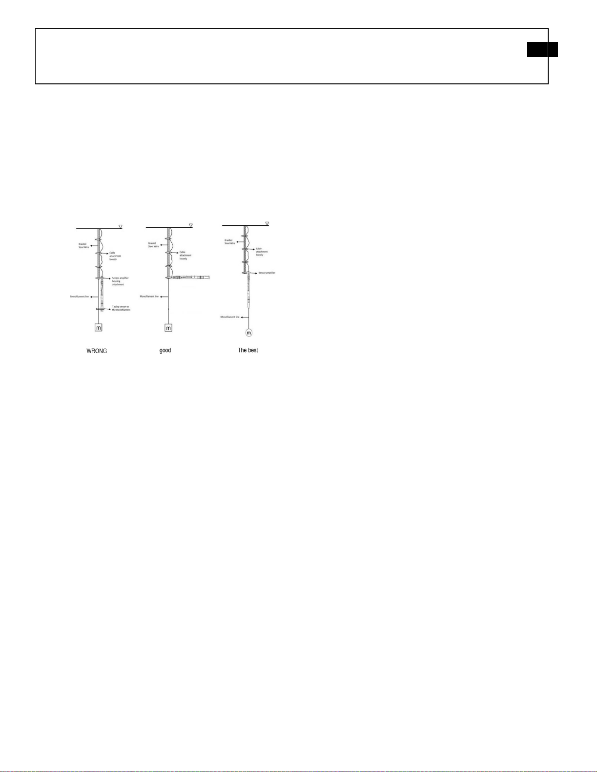
For higher pressure dynamic measurements, alternate
methods of suspending the sensor should be used to
minimize damage from turbulence. Taping or
attaching (with cable ties) the sensor amplifier housing
to a braided steel wire is a method that is suited for use
in higher dynamic pressure measurements.

Drawing Number: 21102
Revision: B
OPERATION MANUAL FOR
3
Series 138
The steel wire can have a weight attached to it to
submerge the entire assembly. Tape or attach the
coaxial cable loosely to the steel wire at ~one foot
intervals. Attach a monofilament line (~50 lb. test) to
the end of a steel wire braid, and let it hang down past
the end of the sensor.
Attach a three to five lb. weight to the end of the
monofilament and tape the sensor to the
monofilament. See Image 1 for reference.
Image 1 – Installation Methods
3.0 OPERATION
It is necessary only to supply the sensor with a 2 to 20
mA constant current at +20 to +30 VDC through a
current-regulating diode or equivalent circuit.
Most PCB signal conditioners have an adjustable
current feature allowing a choice of input currents
from 2 to 20 mA.
In general, for best resolution, choose the lower
current ranges, and for driving long cables (to several
thousand feet) use the higher current, up to 20 mA
maximum. Line-impedance matching may be
necessary to produce flat-frequency response over
long (hundreds or thousands of feet) cables.
Switch power on and observe reading of bias
monitoring voltmeter on front panel of the signal
conditioner.
If indicator is in green section of indicator panel, the
IC amplifier is producing proper bias (+8 to 14 VDC),
cable connections are normal and the system is ready
to operate.
If the needle moves to the red area of the fault monitor
meter, output is zero and a short is indicated. Short
could be located in amplifier, cable connectors, or
power unit.
If the pointer moves into the yellow area of the fault
monitor meter, an open circuit is indicated with full
power supply voltage. An open circuit could be the
result of a faulty amplifier, an open cable or open
connectors.
Allow the sensor to stabilize for about one minute. A
signal drift may occur when cable is connected to the
readout instrument.
This drift occurs during charging of the coupling
capacitor in the power unit. The signal will stabilize
in several minutes.
4.0 CALIBRATION
Series 138 are calibrated dynamically using a drop
weight tester. For best accuracy, use the calibration
certificate supplied. Factory recalibration is available
for a nominal charge.
5.0 POLARITY
This sensor series produces a positive-going output
voltage for increasing pressure input. See the
specification sheet for polarity of the sensor.
6.0 LOW-FREQUENCY RESPONSE
The low-frequency response of an ICP®system is
determined by:
l.) The discharge time constant of the sensors.
2.) If AC-coupled at the power unit, the coupling
time constant.

Drawing Number: 21102
Revision: B
OPERATION MANUAL FOR
4
Series 138
7.0 MAINTENANCE
Observe the following precautions when using the
sensor:
l.) Keep connections clean and dry.
2.) Do not exceed specified maximum range.
3.) Do not subject sensor to temperaturesexceeding
100 °F.
4.) Do not apply voltage to sensor withoutcurrent-
limiting diodes or other current protection.
5.) Do not apply more than 20 mA of current to the
sensor.
®ICP is a registered trademark of PCB Piezotronics,
Inc.

Model Number
138A01 ICP® PRESSURE SENSOR Revision: J
ECN #: 52121
Performan ce EN GLISH SI
Measurement Range(for ±5V output) 1,000 psi 6,895 kPa
Useful Overrange(for ± 10V output) 2,000 psi 13,790 kPa [1]
Sensitivity(± 15 %) 5 mV/psi 0.73 mV/kPa
Maximum Pressure 50,000 psi 344,750 kPa
Resolution 0.02 psi 0.14 kPa [2]
Resonant Frequency ≥ 1,000 kHz ≥ 1,000 kHz
Rise Time(Reflected) ≤ 1.5 µ sec ≤ 1.5 µ sec
Low Frequency Response(- 5 %) 1.7 Hz 1.7 Hz
Non-Linearity ≤ 2.0 % FS ≤ 2.0 % FS [3]
Environmen tal
Temperature Range(Operating) -10 to +100 °F -23 to +37.8 °C
Maximum Shock 20,000 g pk 196 140 m/s² pk
Electrical
Output Polarity(Positive Pressure) Positive Positive
Discharge Time Constant(at room temp) ≥ 0.3 sec ≥ 0.3 sec
Excitation Voltage + 20 to 30 VDC + 20 to 30 VDC
Constant Current Excitation 2 to 20 mA 2 to 20 mA
Output Impedance ≤ 100 Ohm ≤ 100 Ohm
Output Bias Voltage + 8 to 14 VDC + 8 to 14 VDC
Ph ysical
Sensing Element Tourmaline Tourmaline
Housing Material Stainless Steel Stainless Steel
Electrical Connector 10-32 Coaxial Jack 10-32 Coaxial Jack
Weight 0.75 oz 21 gm
[4]
All specifications are at room temperature unless otherwise specified.
In the interest of constant product improvement, we reserve the right to change specifications without notice.
ICP® is a registered trademark of PCB Piezotronics, Inc.
N - Negative Output Polarity
W - Water Resistant Cable
OPTION A L VERSION S
Optional versions have identical specifications and accessories as listed for the standard model except
where noted below. More than one option may be used.
NOTES:
[1]For +10 volt output, minimum 24 VDC supply voltage required. Negative 10 volt output may be
limited by output bias.
[2]Typical.
[3]Zero-based, least-squares, straight line method.
[4]See PCB Declaration of Conformance PS023 for details.
Date: 10/07/2021 Date: 10/07/2021 Date: 10/07/2021 Date: 10/07/2021 138-1010-80
Entered: ND Engineer: RPF Sales: MV Approved: BAM Spec Number:
3425 Walden Avenue, Depew, NY 14043
Phone: 716-684-0001
Fax: 716-684-0987
E-Mail: info@pcb.com

Table of contents
Other PCB Piezotronics Industrial Electrical manuals

PCB Piezotronics
PCB Piezotronics ICP RH204C User manual

PCB Piezotronics
PCB Piezotronics 123B User manual

PCB Piezotronics
PCB Piezotronics 480M122 User manual

PCB Piezotronics
PCB Piezotronics JM353B17 User manual

PCB Piezotronics
PCB Piezotronics 478B05 User manual

PCB Piezotronics
PCB Piezotronics T356M98 User manual

PCB Piezotronics
PCB Piezotronics M1381-001-01A User manual

PCB Piezotronics
PCB Piezotronics 352B10 User manual

PCB Piezotronics
PCB Piezotronics IMI SENSORS 691B35 User manual

PCB Piezotronics
PCB Piezotronics 202M44/050AD User manual