PCT PCT-UMFN-AS-x User manual

www.pctinternational.com
1715 West Sunrise Boulevard | Gilbert, Arizona 85233-5032 | USA
ULTRA MINI FIBER NODE
PCT-UMFN-AS-x
Ver 1a 09052008
PRODUCT
Installation Guide MANUAL
www.pctinternational.com
1715 West Sunrise Boulevard | Gilbert, Arizona 85233-5032 | USA
www.pctinternational.com
1715 West Sunrise Boulevard | Gilbert, Arizona 85233-5032 | USA
ULTRA MINI FIBER NODE
PCT-UMFN-AS-x
Ver 1a 09052008
PRODUCT
Installation Guide MANUAL
www.pctinternational.com
1715 West Sunrise Boulevard | Gilbert, Arizona 85233-5032 | USA

PCT-UMFN-AS-x
MINI FIBER NODE
Ver 1a 09052008 Installation Guide
PCT-UMFN-AS-x
MINI FIBER NODE
Ver 1a 09052008 Installation Guide
Pursuant to the pertinent sections of Title 21 (United States) Code Of Federal Regulation (CFR),
Chapter I, Subchapter J, and administered by the Center For Devices And Radiological Health
(CDRH), operating under the Food And Drug Administration (FDA), this product, which produces or
receives an optical signal composed of Laser Radiation, complies with 21 CFR Chapter I, Subchapter J, as
applicable to Class I laser products.
CAUTION: There are no user serviceable parts contained within the housing. Refer all servicing
to qualified service personnel. Other than specific measurements, adjustments, and tests specified in
this manual, make no attempt to modify or alter any circuit or assembly in any manner.
© 2003-2008 PCT International, Inc. All rights reserved.
Information in this document is subject to change without notice. No part of this document may be reproduced or
transmitted in any form or by any means, electronic or mechanical, for any purpose, without the express written
permission of PCT International, Inc., 1715 West Sunrise Boulevard, Gilbert, AZ 85233-5032, USA.
PCT International, Inc. makes sincere efforts to ensure accuracy and quality of its published materials; however, no
warranty, expressed or implied, is provided. PCT International, Inc. disclaims any responsibility or liability for any direct
or indirect damages resulting from the use of the information in this manual or products described in it. Mention of any
product does not constitute an endorsement by PCT of that product. This manual was originally composed in English
and may subsequently be translated into other languages. The fidelity of the translations cannot be guaranteed.
In case of conflict between the English version and other language versions, the English version takes precedence.
PCT International, Inc. and PCT are trademarks, registered and otherwise, of PCT International, Inc.
INDEX
A. Product Description............................................ 1
B. Features............................................................. 1
C. Packing List........................................................ 1
D. Installation.......................................................... 2
E. Maintenance ...................................................... 3
F. Fiber Optic Downstream Receiver ..................... 4
G. Electrical/Environmental/Mechanical.................. 4
H. Configuration / Ordering Options........................ 4
This page intentionally left blank.
PCT-UMFN-AS-x
MINI FIBER NODE
Ver 1a 09052008 Installation Guide
PCT-UMFN-AS-x
MINI FIBER NODE
Ver 1a 09052008 Installation Guide
Pursuant to the pertinent sections of Title 21 (United States) Code Of Federal Regulation (CFR),
Chapter I, Subchapter J, and administered by the Center For Devices And Radiological Health
(CDRH), operating under the Food And Drug Administration (FDA), this product, which produces or
receives an optical signal composed of Laser Radiation, complies with 21 CFR Chapter I, Subchapter J, as
applicable to Class I laser products.
CAUTION: There are no user serviceable parts contained within the housing. Refer all servicing
to qualified service personnel. Other than specific measurements, adjustments, and tests specified in
this manual, make no attempt to modify or alter any circuit or assembly in any manner.
© 2003-2008 PCT International, Inc. All rights reserved.
Information in this document is subject to change without notice. No part of this document may be reproduced or
transmitted in any form or by any means, electronic or mechanical, for any purpose, without the express written
permission of PCT International, Inc., 1715 West Sunrise Boulevard, Gilbert, AZ 85233-5032, USA.
PCT International, Inc. makes sincere efforts to ensure accuracy and quality of its published materials; however, no
warranty, expressed or implied, is provided. PCT International, Inc. disclaims any responsibility or liability for any direct
or indirect damages resulting from the use of the information in this manual or products described in it. Mention of any
product does not constitute an endorsement by PCT of that product. This manual was originally composed in English
and may subsequently be translated into other languages. The fidelity of the translations cannot be guaranteed.
In case of conflict between the English version and other language versions, the English version takes precedence.
PCT International, Inc. and PCT are trademarks, registered and otherwise, of PCT International, Inc.
INDEX
A. Product Description............................................ 1
B. Features............................................................. 1
C. Packing List........................................................ 1
D. Installation.......................................................... 2
E. Maintenance ...................................................... 3
F. Fiber Optic Downstream Receiver ..................... 4
G. Electrical/Environmental/Mechanical.................. 4
H. Configuration / Ordering Options........................ 4
This page intentionally left blank.

PCT-UMFN-AS-x
MINI FIBER NODE
Ver 1a 09052008 Installation Guide
PCT-UMFN-AS-x
MINI FIBER NODE
Ver 1a 09052008 Installation Guide
F. FIBER OPTIC DOWNSTREAM RECEIVER
RF
Frequency Range 45 to 1002 MHz
Output Level 27 dBmV @ -4 dBm optical input,
80 ch NTSC +300 MHz digital loading
OPTICAL
Bandwidth 1200 to 1600 nm
Input Power -8 to -1 dBm
Connector SC/APC - standard (Other types available)
Return Loss > 55 dB with UPC connector, > 60 dB with APC connector
LINK PERFORMANCE
CNR Better than 48 dB typical @ -4 dBm optical input
CSO Better than –63 dB typical @ -4 dBm optical input
CTB Better than –65 dB typical @ -4 dBm optical input
Impedance 75 Ohms
Output Return Loss > 16 dB
Flatness ±1dB
G. ELECTRICAL/ENVIRONMENTAL/MECHANICAL
Power 15 VDC F-type connector, AC/DC power adapter supplied,
or RF output port with power inserter (optional)
Operating Temperature -40° to +65° C ambient
Humidity Up to 95% non-condensing
Dimensions (WxHxD) 86 x 59.8 x 25.8 mm, 3.4 x 2.4 x 1 in.
Weight 142 g, 5 oz
H. CONFIGURATION / ORDERING OPTIONS
The PCT-UMFN-AS-x needs to be ordered with the appropriate power adapter, based on the country
in which it is going to be used. Please refer to the PCT International, Inc. product catalog for specific
information on the proper power adapter needed.
A. PRODUCT DESCRIPTION
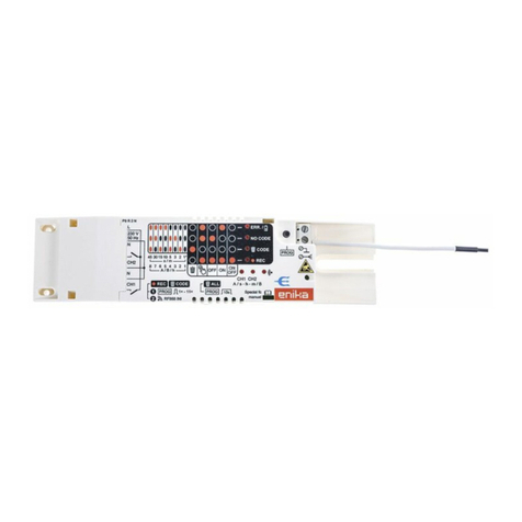
The Ultra Mini Fiber Node (UMFN) is a low cost fiber optic receiver that is engineered
and manufactured to a micro-sized “footprint”. Requiring minimal installation and
maintenance effort, the UMFN is designed for complete functionality in applications
where a full-featured node is not required.
Suited for “limited space” component setups, the UMFN’s applications include: FTTH,
PON, communications and closed-circuit security systems, as well as special events
installations, emergency restorations, and rebuild, upgrade, and retrofit projects.
B. FEATURES
•Small footprint
•20 dB test point for both forward and reverse RF path
•Standard +27 dBmV output at –4 dBm optical input
•Excellent distortion specs
•Low power consumption
•Powered through dedicated F-port or RF output port
•-8 to -1dBm and 1200 to 1600nm forward receiver operation
C. PACKING LIST
•Mini Fiber Node unit
•Power Transformer (per customer specification)
•Product Manual
Page 4 Page 1
PCT-UMFN-AS-x
MINI FIBER NODE
Ver 1a 09052008 Installation Guide
PCT-UMFN-AS-x
MINI FIBER NODE
Ver 1a 09052008 Installation Guide
F. FIBER OPTIC DOWNSTREAM RECEIVER
RF
Frequency Range 45 to 1002 MHz
Output Level 27 dBmV @ -4 dBm optical input,
80 ch NTSC +300 MHz digital loading
OPTICAL
Bandwidth 1200 to 1600 nm
Input Power -8 to -1 dBm
Connector SC/APC - standard (Other types available)
Return Loss > 55 dB with UPC connector, > 60 dB with APC connector
LINK PERFORMANCE
CNR Better than 48 dB typical @ -4 dBm optical input
CSO Better than –63 dB typical @ -4 dBm optical input
CTB Better than –65 dB typical @ -4 dBm optical input
Impedance 75 Ohms
Output Return Loss > 16 dB
Flatness ±1dB
G. ELECTRICAL/ENVIRONMENTAL/MECHANICAL
Power 15 VDC F-type connector, AC/DC power adapter supplied,
or RF output port with power inserter (optional)
Operating Temperature -40° to +65° C ambient
Humidity Up to 95% non-condensing
Dimensions (WxHxD) 86 x 59.8 x 25.8 mm, 3.4 x 2.4 x 1 in.
Weight 142 g, 5 oz
H. CONFIGURATION / ORDERING OPTIONS
The PCT-UMFN-AS-x needs to be ordered with the appropriate power adapter, based on the country
in which it is going to be used. Please refer to the PCT International, Inc. product catalog for specific
information on the proper power adapter needed.
A. PRODUCT DESCRIPTION
The Ultra Mini Fiber Node (UMFN) is a low cost fiber optic receiver that is engineered
and manufactured to a micro-sized “footprint”. Requiring minimal installation and
maintenance effort, the UMFN is designed for complete functionality in applications
where a full-featured node is not required.
Suited for “limited space” component setups, the UMFN’s applications include: FTTH,
PON, communications and closed-circuit security systems, as well as special events
installations, emergency restorations, and rebuild, upgrade, and retrofit projects.
B. FEATURES
•Small footprint
•20 dB test point for both forward and reverse RF path
•Standard +27 dBmV output at –4 dBm optical input
•Excellent distortion specs
•Low power consumption
•Powered through dedicated F-port or RF output port
•-8 to -1dBm and 1200 to 1600nm forward receiver operation
C. PACKING LIST
•Mini Fiber Node unit
•Power Transformer (per customer specification)
•Product Manual
Page 4 Page 1

PCT-UMFN-AS-x
MINI FIBER NODE
Ver 1a 09052008 Installation Guide
PCT-UMFN-AS-x
MINI FIBER NODE
Ver 1a 09052008 Installation Guide
TECHNICAL ASSISTANCE
For further assistance concerning equipment installation, technical questions, or
troubleshooting, contact PCT International, Inc.
D. INSTALLATION
1. FIBER OPTIC DOWNSTREAM RECEIVER
a. Measure optical power at input to receiver
1.) If optical power > -1 dBm, add an optical attenuator until optical level is
between -8 to -1 dBm (optimum = -4 dBm).
2.) If optical power < -8 dBm, performance will be degraded. Check fiber
optic jumpers, ensuring the connectors are clean.
b. Clean optical connector per maintenance instructions. (See section E.)
c. Verify correct optical connector is being used (SC/APC is standard on the
UMFN)
d. Insert optical connector into socket labeled “OPTIC IN”..
2. RF CABLE
a. Install type F-male connectorized RF coaxial cable to “RF OUT” port.
3. POWERING
a. Verify AC voltage rating on the included power adapter is correct for the
available power source.
b. Connect F-male connectorized RF coaxial cable to the power adaptor and
the “POWER IN” port.
c. (Optional) In case of reverse powering through the RF port:
1.) Connect an F-male connectorized RF coaxial cable between
“RF OUT” port on the Mini Fiber Node and the port labeled “TO AMP”
on the power inserter (MPI -1G).
2.) Connect the F-male connectorized RF coaxial cable to the power
adaptor and the port labeled “DC IN” on the power inserter.
3.) Connect F-male connectorized RF coaxial cable from “TO TV” port on
the power inserter to network.
d. Connect the power adaptor to AC voltage source.
4. POWERING ON
a. Check for power light on the Mini Fiber Node, i.e. green LED indicator next
to the “POWER IN” port.
5. RF OUTPUT LEVEL
a. Verify RF output level with a spectrum analyzer or RF field strength meter.
NOTE: If powering through an optional power inserter (MPI-1G), check
the RF output level at the “TO TV” port of the power inserter.
NOTE: Typical levels will be +27 dBmV with –4 dBm optical input to the
“OPTIC IN” port.
E. MAINTENANCE
DANGER: AVOID DIRECT EXPOSURE TO THE LASER BEAM.
Invisible radiation continues when open or when operating with fiber optic cable disconnected.
Never operate unit with a broken fiber or with fiber connector disconnected.
1. Use a lint-free cloth (3 x 3 cm recommended).
2. Moisten one-half of the cloth with >90% pure ethyl alcohol. Gently wipe the
connector end face.
3. Using the dry half of the cloth, wipe the connector face and rapidly shake the
connector.
4. Before fastening the connector, ensure it is completely dry.
CAUTION: To prevent dust-particle abrasion, do NOT spray compressed air
directly onto the connector’s end face.
To avoid eye injury, never look directly into the connector’s end face.
Page 2 Page 3
PCT-UMFN-AS-x
MINI FIBER NODE
Ver 1a 09052008 Installation Guide
PCT-UMFN-AS-x
MINI FIBER NODE
Ver 1a 09052008 Installation Guide
TECHNICAL ASSISTANCE
For further assistance concerning equipment installation, technical questions, or
troubleshooting, contact PCT International, Inc.
D. INSTALLATION
1. FIBER OPTIC DOWNSTREAM RECEIVER
a. Measure optical power at input to receiver
1.) If optical power > -1 dBm, add an optical attenuator until optical level is
between -8 to -1 dBm (optimum = -4 dBm).
2.) If optical power < -8 dBm, performance will be degraded. Check fiber
optic jumpers, ensuring the connectors are clean.
b. Clean optical connector per maintenance instructions. (See section E.)
c. Verify correct optical connector is being used (SC/APC is standard on the
UMFN)
d. Insert optical connector into socket labeled “OPTIC IN”..
2. RF CABLE
a. Install type F-male connectorized RF coaxial cable to “RF OUT” port.
3. POWERING
a. Verify AC voltage rating on the included power adapter is correct for the
available power source.
b. Connect F-male connectorized RF coaxial cable to the power adaptor and
the “POWER IN” port.
c. (Optional) In case of reverse powering through the RF port:
1.) Connect an F-male connectorized RF coaxial cable between
“RF OUT” port on the Mini Fiber Node and the port labeled “TO AMP”
on the power inserter (MPI -1G).
2.) Connect the F-male connectorized RF coaxial cable to the power
adaptor and the port labeled “DC IN” on the power inserter.
3.) Connect F-male connectorized RF coaxial cable from “TO TV” port on
the power inserter to network.
d. Connect the power adaptor to AC voltage source.
4. POWERING ON
a. Check for power light on the Mini Fiber Node, i.e. green LED indicator next
to the “POWER IN” port.
5. RF OUTPUT LEVEL
a. Verify RF output level with a spectrum analyzer or RF field strength meter.
NOTE: If powering through an optional power inserter (MPI-1G), check
the RF output level at the “TO TV” port of the power inserter.
NOTE: Typical levels will be +27 dBmV with –4 dBm optical input to the
“OPTIC IN” port.
E. MAINTENANCE
DANGER: AVOID DIRECT EXPOSURE TO THE LASER BEAM.
Invisible radiation continues when open or when operating with fiber optic cable disconnected.
Never operate unit with a broken fiber or with fiber connector disconnected.
1. Use a lint-free cloth (3 x 3 cm recommended).
2. Moisten one-half of the cloth with >90% pure ethyl alcohol. Gently wipe the
connector end face.
3. Using the dry half of the cloth, wipe the connector face and rapidly shake the
connector.
4. Before fastening the connector, ensure it is completely dry.
CAUTION: To prevent dust-particle abrasion, do NOT spray compressed air
directly onto the connector’s end face.
To avoid eye injury, never look directly into the connector’s end face.
Page 2 Page 3
