manuals.online logo
Brands
  1. Home
  2. •
  3. Brands
  4. •
  5. Halma
  6. •
  7. Receiver
  8. •
  9. Halma BEA 10TD433PB9V User manual

Halma BEA 10TD433PB9V User manual

2 Specications
433MHz TRANSMITTERS & RECEIVER
USER’S GUIDE
DIGITAL TRANSMITTERS AND RECEIVER WITH SEQUENCING FUNCTION
1 Description
DESCRIPTION SPECIFICATION
FREQUENCY 433 MHz
EMITTED RADIO POWER -28.7 dBm (Transmitter)
POWER CONSUMPTION 3mA (Transmitter) 30mA (Receiver)
INPUT VOLTAGE 12 to 24 VAC/DC (Receiver)
CONTACT RATING 1.0 A @ 30 VDC / 0.3 A @ 60 VDC
0.5 A @ 125 VAC
OPERATING TEMPERATURE 14ºF TO 131ºF (-10ºC TO 55ºC)
MAX No. OF PROGRAMMED
UNITS PER RECEIVER
100 TRANSMITTERS
LEDs Receiver Learn
Relay Activation
RED
BLUE
DIMENSIONS Transmitter
Receiver
2 3/4” X 1 3/8” X 9/16” (70mm x 35mm x 14mm)
2 3/4” x 2 1/8” x 1” (70mm x 55mm x 25mm)
CERTIFICATIONS FCC, IC,
75.5092.09 EN 20160623 Page 1 of 4
The 433MHz Series Transmitters and Receiver are ideal for the wireless activation and/or sequencing of automatic doors. The transmitters are available
in hand-held or pushplate styles and they transmit a unique rolling code each time the transmitter is activated (thus providing a secure door opening
signal). The transmitter PN: 10TD433PB9V is powered by a 9-volt battery whereas all other transmitters are powered by a 3 volt battery and all
illuminate a Red LED when activated.
Since receivers can be individually programmed, multiple receivers can be programmed differently thus allowing for sequencing in multiple applications.
Upon activation (pushplate / transmitter), all receivers will acquire the signal at the same time; however, each receiver will respond according to
their programming. Those receivers programmed with NO DELAY will active immediately upon receiving the transmitter signal. Those receivers
programmed with a DELAY will activate at the end of their pre-determined time delay set by the potentiometer. The use of multiple receivers will allow
for the uninterrupted pace or hands free operations through a pair of doors upon initial activation.
10TD433HH
ONE BUTTON 10TD433HH2
TWO BUTTON 10TD433HH3
THREE BUTTON 10TD433HH4
FOUR BUTTON 10TD433PB3V
3V w / LEADS 10TD433PB9V
9V w / LEADS
FCC ID#: G9B-10TD433HH4 IC ID#: 4680A-10TD433HH4
3 Precautions
This wireless receiver is not intended to be used DIRECTLY with maglocks or electric strikes due to possible damage caused by
inductive load kickback. Instead, this wireless receiver should be used to trigger a logic module (Br3) or isolation relay which then
triggers the maglock or electric strike.
Shut off all power going to work area before attempting any wiring procedures.
Maintain a clean & safe environment when working in public areas.
To remain in compliance with Part 15.231, do not operate transmitter (hold down button ) for longer than 5 seconds.
Constantly be aware of pedestrian trafc around the area.
Always stop pedestrian trafc through the doorway when performing tests that may result in unexpected- reactions by the door.
ESD: Circuit boards are vulnerable to damage by electrostatic discharge. Before handling ensure you dissipate your body’s charge.
Always check placement of components before powering up so that moving parts will not catch any wires or cause damage to
equipment.
Ensure compliance with all applicable safety standards (i.e. ANSI A156.10 / 19) upon completion of installation.
DO NOT attempt any internal repair of the components. All repairs and/or component replacements must be performed by BEA,
Inc. Unauthorized disassembly or repair:
1. May jeopardize personal safety and may expose one to the risk of electrical shock.
2. May adversely affect the safe and reliable performance of the product resulting in a voided warranty.
ANTENNA WIRE
DIP
SWITCH
LEARN WITH
DELAY BUTTON
LEARN
W/O DELAY
BUTTON
DELAY
POTENTIOMETER
(Time Adjustment)
TERMINAL
STRIP
RED LED
BLUE LED
Page 2 of 4 75.5092.09 EN 20160623
OUTER
RECEIVER
1
2
3
INNER
RECEIVER
4
1 DIP SWITCH SETTINGS
2 HAND HELD CONFIGURATION
1. Set dip switches on the receiver to the desired activation cycle (dip switch 1 -Toggle or Pulse and dip switch 2 - 0.5s or 10s hold).
2. Press either Learn w/Delay Button or Learn w/No Delay Button on the receiver depending on the activation requirements
(If delay learn is selected, adjust potentiometer to counterclockwise limit, 0 second delay). After learn cycle is complete, adjust
potentiometer to desired delay time (0-30 sec).
3. Depress transmitter button repeatedly until Blue LED on the receiver illuminates (indicating reception of signal from transmitter).
NOTE: Repeat Steps 2-3 to program additional transmitters.
4. To test the system, depress transmitter button (Red LED on Transmitter will illuminate) and observe that the Blue LED illuminates on the
receiver. This indicates that the relay has been activated.
3 PUSH PLATE CONFIGURATION
1. Before beginning, it is easiest to have already prepared the installation of the pushplate.
2. Connect the wires from the transmitter to the NO and COM contacts of the pushplates switch.
3. Follow Steps 1-4 (Hand-Held Conguration); depress the pushplate to activate the transmitter.
4. Attach the transmitter to the inside of the electrical box and complete the installation.
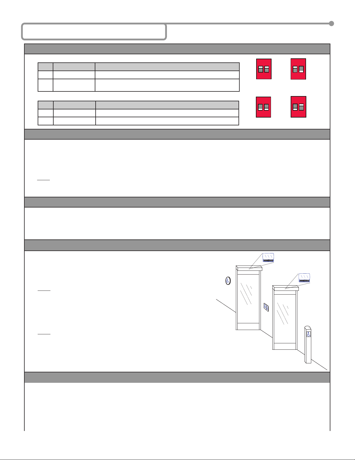
4 TYPICAL VESTIBULE APPLICATION
A OUTSIDE TRANSMITTER (PUSH PLATE)
1. Press Learn w/NO DELAY BUTTON on OUTER Receiver then press Transmitter 1.
2. Press Learn w/DELAY BUTTON on INNER Receiver then press Transmitter 1.
NOTE: Set Potentiometer to desired Delay Time per Hand Held Conguration Step #2.
B INSIDE TRANSMITTER (PUSH PLATE)
1. Press Learn w/NO DELAY BUTTON on INNER Receiver then press Transmitter 2.
2. Press Learn w/DELAY BUTTON on OUTER Receiver then press Transmitter 2.
NOTE: Set Potentiometer to desired Delay Time per Hand Held Conguration Step #2.
C VESTIBULE TRANSMITTERS (Dual Switch Pushplate or Two Separate Pushplates)
1. Press Learn w/NO DELAY BUTTON on INNER Receiver then press Transmitter 3.
2. Press Learn w/NO DELAY BUTTON on OUTER Receiver then press Transmitter 4.
5 REMOVING TRANSMITTER CODE(S)
SINGLE TRANSMITTER CODE
1. Press both DELAY and NO DELAY BUTTONS simultaneously until Red LED ashes once (approximately 1 second).
2. Press transmitter button twice within 10 seconds and the transmitter code will be deleted.
ALL TRANSMITTER CODES
1. Press and hold both DELAY and NO DELAY BUTTONS simultaneously until Blue LED illuminates then release (approximately 10
seconds).
4 Programming
# 1 DESCRIPTION FUNCTION
OFF Pulse Relay Press the transmitter once and the relay will be active momentarily.
ON Toggle Relay Press the transmitter once and the relay output is active indenitely,
press it again and the relay will de-energize indenitely.
# 2 DESCRIPTION FUNCTION (Pulse Mode Only)
OFF 0.5 sec Hold Time Relay will remain active 0.5 second after the loss of activation.
ON 10 sec Hold Time Relay will remain active 10 seconds after the loss of activation.
1 2
ON
0.5s l 10s
PUL TOG
1 2
ON
0.5s l 10s
PUL TOG
In Toggle Setting (1-ON), the Hold Time
is inactive. Either setting for #2 dip
switch will have the same result.
1 2
ON
0.5s l 10s
PUL TOG
1 2
ON
0.5s l 10s
PUL TOG
0.5 second
Pulse Setting
10 second
Pulse Setting
75.5092.09 EN 20160623 Page 3 of 4
6 Battery Replacement
CAUTION: THERE IS A RISK OF EXPLOSION IF AN INCORRECT BATTERY TYPE IS USED.
DISPOSE OF USED BATTERIES ACCORDING TO ITS INSTRUCTIONS.
1 3 - VOLT TRANSMITTERS
1. Remove two screws from back of transmitter.
2. Separate housing and install a fresh 3-Volt (Type CR2032) battery making sure to observe proper polarity.
3. Reassemble housing and replace screws.
NOTE: Don’t throw used batteries away with the general trash. Discard per your local municipal laws and regulations.
2 9 - VOLT TRANSMITTER
1. Remove old battery.
2. Connect a fresh 9-Volt (Type 6LR61) battery making sure to observe proper polarity.
NOTE: Don’t throw used batteries away with the general trash. Discard per your local municipal laws and regulations.
7 FCC Compliance
• This Digital Transmitter complies with Part 15 of the FCC rules. Operation is subject to the following two conditions:
1) This device may not cause harmful interference and;
2) This device must accept any interference received including interference that may cause undesired operations.
a) This equipment has been tested and found to comply with the limits for a Class B digital device, pursuant to part 15 of the FCC
Rules. These limits are designed to provide a reasonable protection against harmful interference in a residential installation.
This equipment generates, uses and can radiate radio frequency energy and, if not installed and used in accordance with the
instruction, may cause harmful interference to radio communications. However, there is no guarantee that interference will not
occur in a particular installation. If this equipment does cause harmful interference to radio or television reception, which can be
determined by turning the equipment off and on, the user is encouraged to try to correct the interference by one or more of the
following measures:
• Reorient or relocate the receiving antenna.
• Increase the separation between the equipment and receiver.
• Connect the equipment into an outlet on a circuit different from that to which the receiver is connected.
• Consult the dealer or an experienced radio/ TV technician for help.
• This transmitter operates in the band 433.5- 434.5 MHz and is restricted to periodic transmissions of up to 5 seconds.
• Changes or modications not expressly approved by BEA, Inc. for compliance could void the user’s authority to operate the equipment.
• Devices authorized under these provisions shall be provided with a means for automatically limiting operation so that the duration
of each transmission shall not be greater than 60 seconds and be only permitted to re initiate an interrogation in the case of a
transmission error.
FCC ID#: G9B-10TD433HH4 IC ID#: 4680A-10TD433HH4
5 Wiring
Power VAC/DC Output
Label 12 - 24 12 - 24 Com. N.O. N.C.
Wire Color Red (+) Black (-) White Green Grey
Terminal 1 2 3 4 5
Description Control or Transformer power Control Common Control Activation Typically not used
9 Company Contact
75.5092.09 EN 20160623 Page 4 of 4
8 Troubleshooting
Problem: THE RED LED ON MY RECEIVER IS JUST FLICKERING AND I’M UNABLE TO PROGRAM AND/OR IT WON’T WORK.
Solution:You have a push plate stuck or faulty transmitter. Disconnect each push plate until the LED goes out. If LED does not go out, remove
each transmitter battery until it does. Replace the appropriate transmitter.
Problem: HOW DO I ERASE ONLY ONE TRANSMITTER CODE?
Solution: Press both the delay and no delay buttons simultaneously on the receiver for approx. 1 second or until the red LED starts ashing on &
off then release. Press the transmitter button twice within 10 seconds and the given transmitter code will be deleted.
Problem: HOW DO I ERASE THE MEMORY ON THE 433 RECEIVER?
Solution: Press both the delay and no delay buttons simultaneously on the receiver until the blue LED illuminates then release (aprox. 10 sec-
onds).
Problem: RECEIVER INTERMITTENTLY DOESN’T RECEIVE THE TRANSMITTER(S) SIGNAL.
Solution: You may extend the receiver antenna wire only in multiples of 6.75” (6 3/4”). i.e. 6.75 x 4 = 27 inches of extended antenna wire
24/7 Tech Support: 1-800-407-4545 | Customer Service: 1-800-523-2462 | General Tech Questions: T[email protected] | Tech Docs: www.beasensors.com

This manual suits for next models

5

Popular Receiver manuals by other brands

PCB Piezotronics ICP JM353B16 Installation and operating manual

PCB Piezotronics

PCB Piezotronics ICP JM353B16 Installation and operating manual

Ferguson ARIVA 100E user manual

Ferguson

Ferguson ARIVA 100E user manual

Magenta Research MultiView II AK600DP Installation and user guide

Magenta Research

Magenta Research MultiView II AK600DP Installation and user guide

urmet domus 1092/303 instructions

urmet domus

urmet domus 1092/303 instructions

IRS RF-11 user manual

IRS

IRS RF-11 user manual

JVC RX-664VBK instructions

JVC

JVC RX-664VBK instructions

Kenwood KR-V9020 instruction manual

Kenwood

Kenwood KR-V9020 instruction manual

Topfield TF-S3000CHD quick guide

Topfield

Topfield TF-S3000CHD quick guide

Dual XRM47BT user manual

Dual

Dual XRM47BT user manual

Kaos PDR1 user guide

Kaos

Kaos PDR1 user guide

Sony STR-DG1200 Specifications

Sony

Sony STR-DG1200 Specifications

Cambridge Audio AZUR 651A Service manual

Cambridge Audio

Cambridge Audio AZUR 651A Service manual

Magenta MultiView II DVI-Rx-1K Installation and user guide

Magenta

Magenta MultiView II DVI-Rx-1K Installation and user guide

MODI MODI-01 user guide

MODI

MODI MODI-01 user guide

DirecTV D12-300 Brochure & specs

DirecTV

DirecTV D12-300 Brochure & specs

Itowa IT3R22 user manual

Itowa

Itowa IT3R22 user manual

evertz 7700 Series manual

evertz

evertz 7700 Series manual

Pioneer AVH-X7700BT quick start guide

Pioneer

Pioneer AVH-X7700BT quick start guide

manuals.online logo
manuals.online logoBrands
  • About & Mission
  • Contact us
  • Privacy Policy
  • Terms and Conditions

Copyright 2025 Manuals.Online. All Rights Reserved.