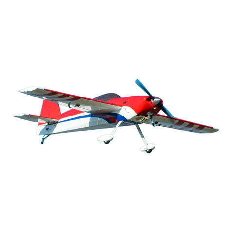
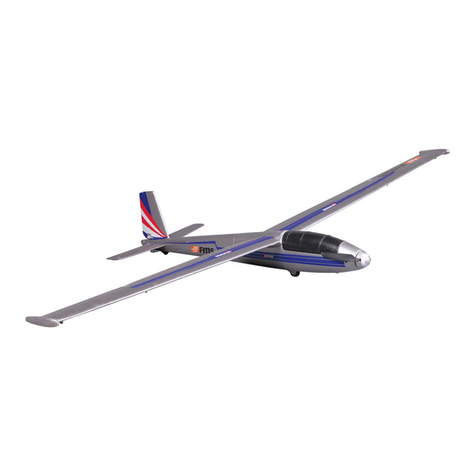
PD CERASIS DG 600/270 User manual

-
1
-
DG 600/270 and DG 600/320
Assembly instruction

-
2
-
Building of model DG 600
Wing:
The next picture shows the aileron servo installation as viewed from the front of the wing. Open up the covering over
the aileron servo bays with a sharp hobby knife and remove any material that fills the bays down to the wood. Guide the servo
wires through the routed wing channels until the connectors on the end of the wires emerge from the wing roots. Make sure
the aileron servos are facing the right direction and adjust the position of the aileron servo arm by connecting the servo wire to
the receiver, connecting the battery to the receiver, then turn the transmitter on. Make sure all trims are centered and your
servo will be in the neutral position. Adjust the servo arm by removing the servo arm screw and push the servo arm back on
with the servo arm facing forward (in respect to the plane) at an angle of 40 degrees from the wing surface.
Once you‘re sure you have the servos in the correct position and they fit well in the wing bays, disconnect them from
the receiver, turn off the transmitter and glue or double-sided tape the servos in place in the wing. Place and then attach the
aileron control horns on the ailerons directly back from the servo arms and install the linkage. The throws for the aileron
should be 15 degrees up and 7 degrees down. If you have a computer radio, program you first settings for these values. If
your radio is programmable, you can adjust the aileron deflections using this feature. If you radio does not permit this
adjustement, then manually adjust the servos as shown in the picture.

-
3
-
Note the drawing of the aileron horn and the servo arm. The arm should be set at 70° with the radio on, all trims set at
zero, and the aileron horizontal to the wing.
The wire pushrod is attached to the clevis using a threaded coupler.

-
4
-
Use a Y-connector to attach the two servo wires together. This connection will be plugged into the receiver aileron
channel when you are ready for final assembly.
Fuselage:
Carefuly cut the canopy from the furnished material to fit the canopy frame. Glue the canopy to the frame using CA or
any other type of glue compatible with these materials.
The canopy frame is attached to the fuselage by fitting a small piece of dowel to the front portion of the frame to fit
into the front part of the fuselage. An included latch is used to hold the rear of the canopy in place. It is important to fit the
canopy carefully, because this will be your acces hatch for the receiver, the servos, and the wing attachement.
Make a 1/8th inch (3mm) plywood platform for mounting servos as per the dimensions in the diagram (in milimeters).
If the retract gear is not installed, make the platform only 80 mm long (you will not need cut-out for third servo).
Glue the servo holder to the fuselage and mount servos.

-
5
-
The same way make a platform for installation of airbrake servo.
Glue this holder into the fuselage as seen on the drawing, so that the servo lever is parallel with holes for control of airbrakes.
Push the piano wires trough bowdens in the fuselage. Inside the canopy glue triangular supports for bowdens, to avoid the
pushrod to go broken. Shorten the rudder pushrod and solder the clevis holder in the fuselage. For the elevator solder the
clevis holders on both sides of bowden for easy decomposition of the elevator and fuselage. Control of airbrakes make when
the wings are attached on the fuselage. Adjust longer of wires so that they allow fully close and open the brakes. Check if
airbrakes open simultanely. Link the retract gear servo with its control level to control the retract gear.

-
6
-
Plug in the elevator and aileron connector(s) and with the transmitter throttle control in the OFF position, plug in the
battery and turn the reciever and transmitter on. Test the control throws per the instructions and make sure everything‘s going
in the right direction. Once you‘ve got it the way you want it, switch the receiver switch off, turn the transmitter off,
disconnect the battery and wrap the receiver in foam rubber and attach it into the fuselage using hook and loop fasteners or

-
7
-
double-sided tape. Then install more hook and loop material on the fuselage floor to hold the battery in flight (and help adjust
center of gravity when needed).
Route the antenna out of the fuselage behind the canopy and attach it using clear tape to the fin. Attach the wing using
the nylon screws and test the center of balance as shown.
The balance point should at the wing root if adjusting the battery location doesn‘t bring the Ventus into balance, add
some lead as far into the nose as you can get it
The main hinge
Suggested control throws:
ailerons +15° -7°
elevator +-10°
rudder +-20 °
Trimming of the model:
If all of the instructions have been followed to this point, the DG 600 is ready to fly.
For best results, use an aircraft tow („aerotow“) to get the DG 600 up to a safe altitude for trimming. Upon realise,
trimm the DG 600 to be stable in all regimes and test control movements and the DG 600´s reactions. After landing, adjust the
control clevises until the controls match your preferences and the DG 600 is trimmed properly. If an aerotow is not available,
hand throw the DG 600 over tall grass with level throws to test and adjust trims.
Your DG 600 is now ready for slope flying.
We wish you many happy flights with your DG 600
PG GERASIS spol. s.r.o.
This manual suits for next models
1
Table of contents


