PDi WaveStar Manual instruction
WaveStar®
Color Monitor
Setup and Operation
Ctrl Nr: PM375103
Revision: 003

WaveStar Color Monitor ___________________________________________________________
Ctrl Nr: PM375103 Revision: 003 2
Thank you for your recent purchase of a WaveStar®Color Monitor from Power Distribution, Inc.
For safety reasons as well as to ensure optimal performance of your WaveStar®Color Monitor, please
carefully read the instructions before trying to install, operate, service or maintain the system.
For any questions regarding the installation, operation, service or maintenance of your WaveStar®
Color Monitor, please contact us:
Power Distribution, Inc. | 4200 Oakleys Court | Richmond, VA 23223
+1 804 737 9880 | +1.800.225.4838
pdicorp.com | service@pdicorp.com
WaveStar® Color Monitor
Setup and Operation
Ctrl Nr: PM375103 Revision: 003
Release Date: December 2017
© 2017 by Power Distribution, Inc. All rights reserved.
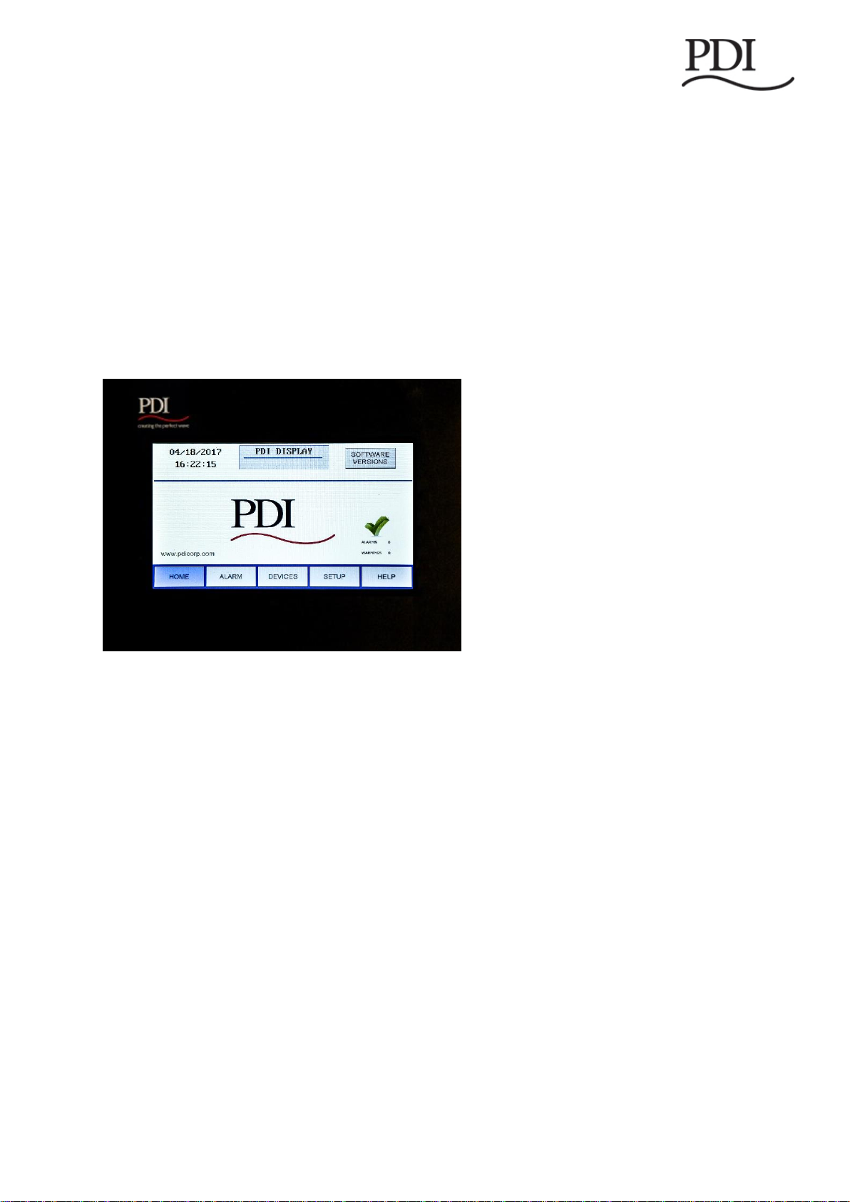
Cover Photo: WaveStar® Color Monitor Home Screen
PDI, JCOMM, Quad-Wye, ToughRail Technology, and WaveStar are registered trademarks of Power
Distribution Inc. All other trademarks are held by their respective owners.
Power Distribution, Inc. (PDI)
Power Distribution, Inc. (PDI) designs, manufactures, and services mission critical power distribution, static switches, and
power monitoring equipment for corporate data centers, alternative energy, industrial and commercial customers around the
world. For over 30 years, PDI has served the data center and alternative energy markets providing flexible solutions with the
widest range of products in the industry.
.

Contents________________________________________________________________________
Ctrl Nr: PM375103 Revision: 003 3
Contents
Safety ............................................................................................6
1Introduction..........................................................................7
1.1 WaveStar Color Monitor Summary....................................................... 7
1.2 Power On and Access......................................................................... 7
1.3 Screen Summary and Navigation ........................................................ 8
1.4 Entering Data ................................................................................... 8
2Color Monitor Networking ...................................................10
2.1 Supported Protocols ........................................................................ 10
2.2 Monitor Network Connections ........................................................... 10
2.2.1 Modbus RTU Ports................................................................. 11
2.2.2 Modbus RTU 2-Wire vs. 4-Wire Configuration ........................... 11
2.3 Modbus RTU Cables ......................................................................... 12
2.3.1 Cable Specification................................................................ 12
2.3.2 Cable Biasing and Termination................................................ 12
2.4 Ethernet Cables .............................................................................. 12
2.5 Customer Modbus RTU Connections ................................................... 12
2.5.1 Power Distribution Unit (PDU)................................................. 13
2.5.1 Remote Power Panel (RPP)..................................................... 14
2.5.1 JCOMM ................................................................................ 14
2.6 Modbus Addressing ......................................................................... 15
2.7 Communicating with the Monitor: Commands and Replies .................... 16
2.7.1 Modbus Commands and Replies.............................................. 16
2.7.2 Limit on Open Sockets........................................................... 16
2.7.3 SNMP Commands.................................................................. 16
3Setup: Monitor and Network ...............................................17
3.1 SETUP: Miscellaneous Parameters ..................................................... 17
3.2 Network Setup................................................................................ 18
3.2.1 Downstream Modbus Device Chain Setup................................. 18
3.2.2 Modbus RTU Setup................................................................ 18
3.2.3 TCP/IP and Modbus TCP/IP Setup ........................................... 19
3.2.4 SNMP Setup ......................................................................... 19
3.2.5 Loading INI Parameters from an SD Card................................. 20
3.3 Software Versions ........................................................................... 20
4Device Chain: Settings ........................................................22
4.1 Initial Device Chain ......................................................................... 22
4.2 Device Settings............................................................................... 23

WaveStar Color Monitor ___________________________________________________________
Ctrl Nr: PM375103 Revision: 003 4
4.2.1 PDU Device Settings.............................................................. 23
4.2.2 Enhanced Subfeeds Settings .................................................. 24
4.2.3 BCMS Normal and KWH Settings............................................. 24
4.2.4 BCMS CB Subfeeds Settings ................................................... 25
4.2.5 BCMS IEC Settings................................................................ 26
5Device Chain: Readings .......................................................27
5.1 PDU Device Readings....................................................................... 27
5.2 Enhanced Subfeeds (ESF) Readings................................................... 28
5.3 BCMS (Normal) Panelboard Readings................................................. 30
5.4 BCMS KWH Readings ....................................................................... 31
5.5 BCMS CB (Subfeeds) Readings.......................................................... 33
5.6 BCMS IEC Readings ......................................................................... 33
6Alarms and Troubleshooting ...............................................35
6.1 Summary Alarm Indicators ............................................................... 35
6.2 Alarm Screen and Alarm List............................................................. 35
6.3 Alarms by Device Type..................................................................... 37
6.3.1 Color Monitor Alarms............................................................. 37
6.3.2 PDU Alarms.......................................................................... 37
6.3.3 Enhanced Subfeeds ............................................................... 39
6.3.4 BCMS Panelboard—Typical Alarms .......................................... 40
6.4 Troubleshooting .............................................................................. 40
7Web Pages ..........................................................................42
Glossary ......................................................................................46
Bibliography ................................................................................47
Appendix: Color Monitor Backpanel .............................................48
Tables
Table 1 Pin-Out for Modbus Headers ...................................................................................................11
Figures
Figure 1 WaveStar Color Monitor Installed in a JCOMM........................................................................7
Figure 2 HOME Screen and Navigation Buttons ....................................................................................8
Figure 3 Entering Alphanumeric Data.....................................................................................................9
Figure 4 Color Monitor Network Connections.......................................................................................10
Figure 5 Color Monitor 4-wire Modbus Connections ............................................................................12
Figure 6 Modbus RTU Connections: PDU Basic Contractor Board .....................................................13
Figure 7 Modbus RTU Connections: PDU Enhanced Contractor Board..............................................13
Figure 8 Modbus RTU Customer Connection: RPP Upstream.............................................................14

Contents________________________________________________________________________
Ctrl Nr: PM375103 Revision: 003 5
Figure 9 JCOMM Modbus Connections................................................................................................14
Figure 10 Modbus Addressing..............................................................................................................15
Figure 11 SETUP Screen......................................................................................................................17
Figure 12 Calibrating the Touchscreen.................................................................................................17
Figure 13 Modbus RTU Setup ..............................................................................................................18
Figure 14 Modbus TCP/IP and SNMP Setup........................................................................................19
Figure 15 Model Information.................................................................................................................20
Figure 16 Initial Device List...................................................................................................................22
Figure 17 Settings: PDU Device ...........................................................................................................23
Figure 18 Settings: Enhanced Subfeeds (ESF)....................................................................................24
Figure 19 Settings: BCMS Device ........................................................................................................25
Figure 20 Settings: BCMS Subfeeds ....................................................................................................25
Figure 21 Settings: BCMS IEC .............................................................................................................26
Figure 22 Readings: PDU.....................................................................................................................27
Figure 23 Readings: Enhanced Subfeeds (ESF) (Part 1).....................................................................28
Figure 24 Readings: Enhanced Subfeeds (ESF) (Part 2).....................................................................29
Figure 25 Readings: BCMS (Normal) ...................................................................................................30
Figure 26 Readings: BCMS KWH (Part 1)............................................................................................31
Figure 27 Readings: BCMS KWH (Part 2)............................................................................................32
Figure 28 Readings: BCMS CB (Two Subfeeds)..................................................................................33
Figure 29 Readings: BCMS IEC Panelboard........................................................................................34
Figure 30 Alarm and Warning Summary Status Icons..........................................................................35
Figure 31 ALARM Screen with an Alarm List........................................................................................36
Figure 32 Find the Circuits in an Alarm Condition ................................................................................36
Figure 33 Web Pages: Home Page ......................................................................................................42
Figure 34 Web Pages: Device Chain....................................................................................................42
Figure 35 Web Pages: Display Device .................................................................................................43
Figure 36 Web Pages: PDU Board.......................................................................................................44
Figure 37 Web Pages: Enhanced Subfeeds.........................................................................................45
Figure 38 Color Monitor Backpanel ......................................................................................................48

Safety __________________________________________________________________________
Ctrl Nr: PM375103 Revision: 003 6
Safety
Please pay special attention to the use of “Danger” symbols throughout this manual indicating
electrical or other safety hazards. Following these safety instructions is extremely important to avoid
possible injury or death.
Follow safe electrical work practices:
•Read, understand, and follow the instructions before installing this product.
•Electrical equipment should be installed, operated, serviced, and maintained only by
qualified personnel and in accordance with all local safety codes. Power Distribution,
Inc. assumes no responsibility for any consequences arising out of the use of this
manual. This document should not be viewed as sufficient by otherwise non-qualified
personnel to operate, service, or maintain the equipment discussed.
•Disconnect and lock-out all power supplying equipment before working on or
installing WaveStar®Color Monitor components. Use a properly rated voltage sensing
device to confirm power is OFF.
•Install device in an appropriate electrical enclosure per local regulations.
•ESD sensitive equipment. Ground yourself, discharge any static charge and ensure
that the device is effectively grounded before handling the unit.
The WaveStar®Color Monitor must be installed by licensed electricians or
by PDI-authorized technicians.
DANGER!
Severe or fatal injury can result from electrical shock during contact with high
voltage conductors, monitoring PCBs, or similar equipment.
Disconnect power before drilling holes, attaching conduit, and attaching WaveStar®
Color Monitors to PDUs, RPPs, or other power distribution equipment.
Use Lock Out/Tag Out procedures.
Wear suitable personal protective clothing and use protective equipment for
performing mechanical and electrical installations.
Leave ample space for attaching and routing wires.
Introduction_______________________________________________________________________
Ctrl Nr: PM375103 Revision: 003 7
1Introduction
1.1 WaveStar Color Monitor Summary
The WaveStar®Color Monitor is a 7-inch color touchscreen which displays power management
information for up to twenty (20) Branch Circuit Monitoring System (BCMS) devices and other PDI
devices in the Monitor’s downstream Modbus network.
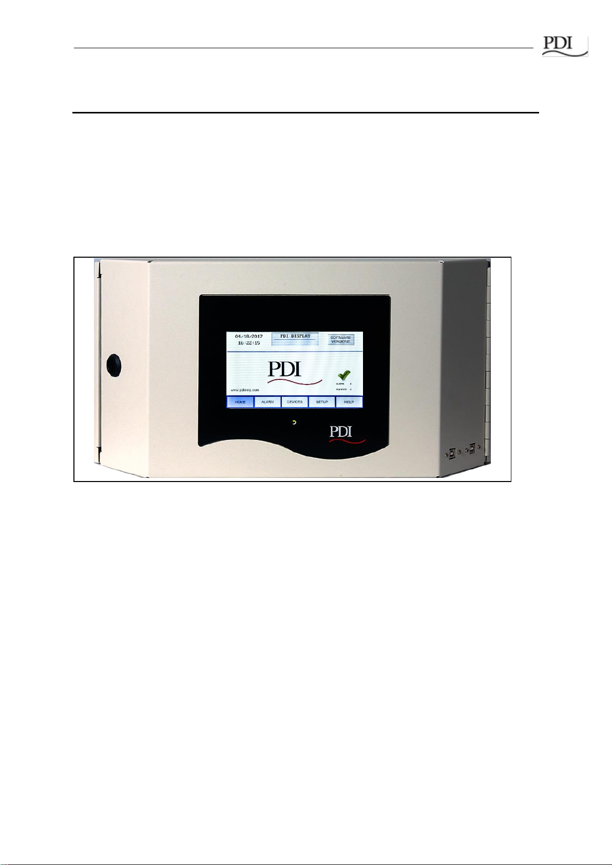
The Color Monitor is incorporated into PDI products, such as PDUs, RPPs, or JCOMM®s, and can
also function as a stand-alone power monitoring station.
Figure 1 shows the Monitor used in a JCOMM®.
Figure 1 WaveStar Color Monitor Installed in a JCOMM
1.2 Power On and Access
The Color Monitor does not have an on/off switch. The Monitor automatically powers-on whenever
power is applied to the unit in which it is installed.
When the unit is powered on for the first time, the Home Screen appears (Figure 2).
The Color Monitor is accessed by touching the screen. If the unit is powered up and is not touched for
15 minutes, the backlight will turn off to save power. The backlight turns back on when the operator
again touches the screen, showing the last displayed screen.
WaveStar Color Monitor_____________________________________________________________
Ctrl Nr: PM375103 Revision: 003 8
1.3 Screen Summary and Navigation
Setup and configuration information for the Color Monitor are on these screens:
•SETUP: system parameters, such as number of devices in Monitor’s chain
•Device SETTINGS: Device-specific parameters, such as user-specified device name
(DEVICES Device Name SETTINGS)
•SOFTWARE VERSIONS: a list of software versions for each device, accessible only from
the HOME screen.
•DEVICES screen gives a list of all devices in the Monitor’s chain.
•Device SETTINGS screen lets you set device name and parameters specific to the
device.
Setpoints in the device’s points list, such as breaker alarm thresholds, are not viewable or modifiable
on the Monitor.
Power monitoring information as it is stored in each device’s points list (or Modbus register map) is in
each DEVICE READINGS screen.
Alarms and warnings are displayed on these screens:
•ALARM: List of all extant warnings and alarms by device name
•All screens: Warning and alarm summary counts
HELP screen contains Modbus information.
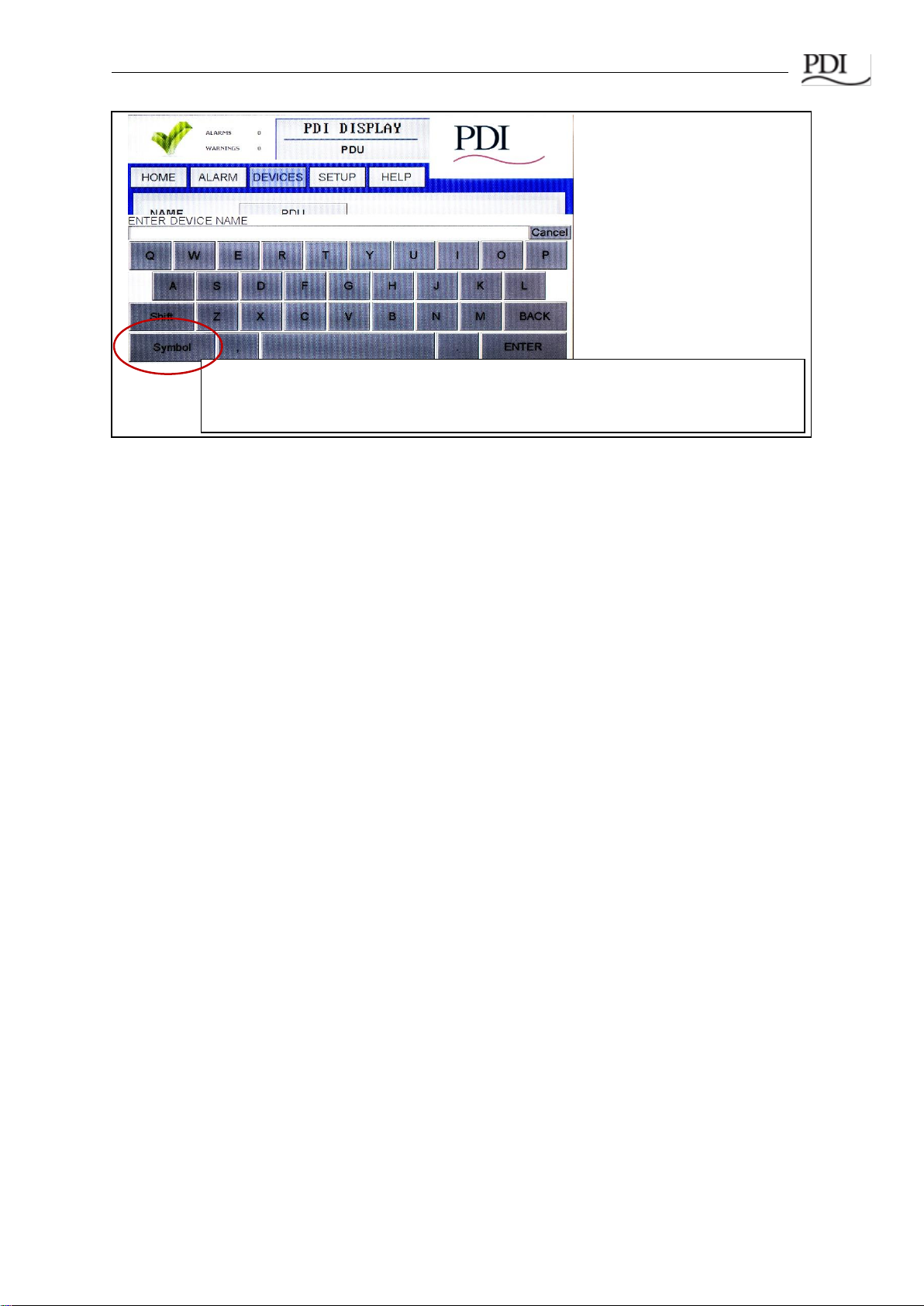
1.4 Entering Data
When you touch a field that requires alphanumeric data, such as device names, passwords, or
version numbers, a touchscreen keyboard will appear, prompting you for information based on
context. You can toggle between LETTERS and SYMBOLS keyboards, for entering text or numbers
(Figure 3).
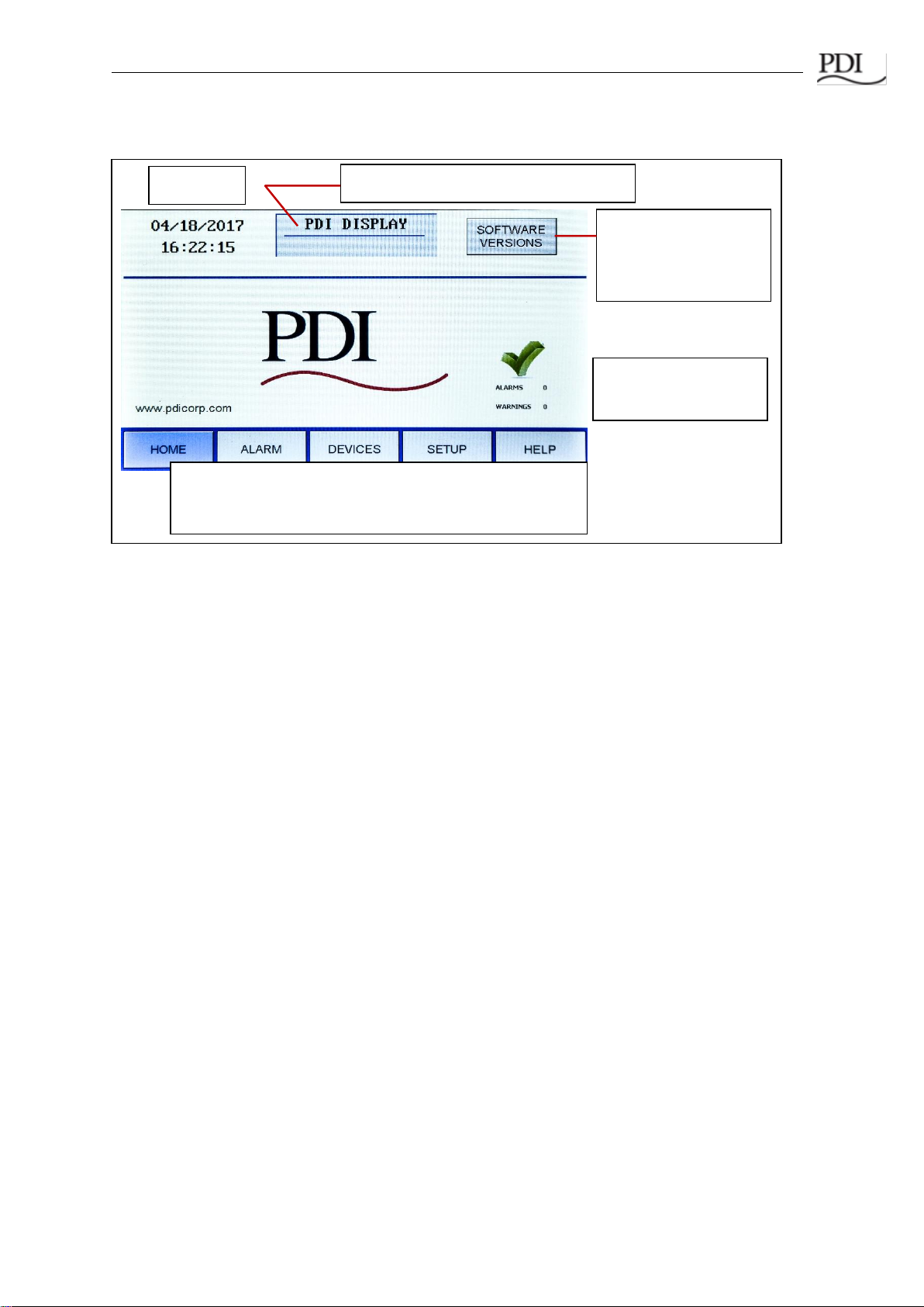
•The main navigation buttons are present on each screen.
•Touch a button to select that screen.
•
Button turns blue when selected.
Banner, user-specified on SETUP screen
SOFTWARE
VERSIONS button is
only displayed on the
HOME
screen.
Date/Time
Alarm summaries are
given on each page.
Figure 2 HOME Screen and Navigation Buttons
Introduction_____________________________________________________________________
Ctrl Nr: PM375103 Revision: 003 9
Touch here to toggle between Symbol and Letters keyboards as you enter model
information.
Touch
ENTER
to complete the operation. Touch
Cancel
to terminate the operation.
Figure 3 Entering Alphanumeric Data
WaveStar Color Monitor_____________________________________________________________
Ctrl Nr: PM375103 Revision: 003 10
2Color Monitor Networking
2.1 Supported Protocols
All protocols supported by the Color Monitor can be used simultaneously.
Downstream Protocol The downstream device network has fixed parameters of Modbus RTU, 9600
baud, EVEN parity.
Upstream Protocols There are separate upstream ports for Modbus RTU and Ethernet, supporting
these protocols:
•Modbus RTU
•Ethernet port
•TCP/IP, used by the web page server (see Chapter 7, Web Pages)
•Modbus TCP/IP
•SNMP Version 1
2.2 Monitor Network Connections
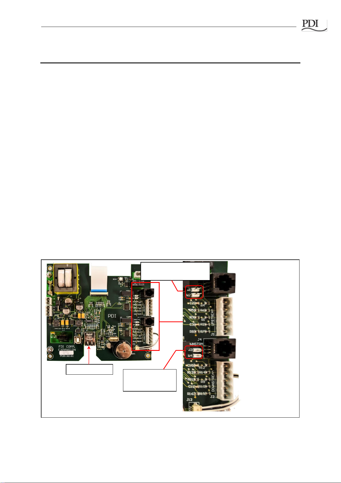
The Color Monitor’s backpanel has Modbus RTU and Ethernet ports (Figure 4).
For Color Monitors embedded in PDI products (PDUs, RPPs, or JCOMMs), Modbus RTU backpanel
connections are typically made in manufacturing and extended to a terminal block or external panel
for convenient customer access. See 2.5 Customer Modbus RTU Connections.
The customer’s Ethernet cable is connected directly to the Monitor’s Ethernet port.
J2: Modbus RTU
Upstream
RJ12 Connection
(to PDU M4G Board)
J4: Modbus RTU
Downstream
RJ12 Connection
(to PDU M4G Board)
J1: Modbus RTU
Upstream
Connection (except
PDU M4G Board)
J3: Modbus RTU
Downstream
Connection (except
PDU M4G Board)
Ethernet Port
Jumper W1, W2 for
2-wire Modbus upstream
Jumper W3, W4 for
2-wire Modbus
downstream
Figure 4 Color Monitor Network Connections

Color Monitor Networking________________________________________________________
Ctrl Nr: PM375103 Revision: 003 11
2.2.1 Modbus RTU Ports
The Color Monitor has four (4) paralleled Modbus ports:
•J1 and J3 are header/plug connections for connecting to most devices.
oJ1 is the upstream port.
oJ3 is the downstream port.
•J2 and J4 accept standard RJ12 phone cable plugs for connection to an M4G PDU
board.
oJ2 is the upstream port.
oJ4 is the downstream port.
The Modbus RTU interface is isolated, and pin designations are given in Table 1:
Pin
J1, J3
J2 (for RJ12 plugs)
J4 (for RJ12 plugs)
1
Ground
Not used
Not used
2
RX-
RX-
TX-
3
RX+
TX-
RX-
4
TX-
RX+
TX+
5
TX+
TX+
RX+
6
NA
Ground
Ground
Table 1 Pin-Out for Modbus Headers
2.2.2 Modbus RTU 2-Wire vs. 4-Wire Configuration
PDI devices have two (2) jumpers near their Modbus ports for configuring 2-wire vs. 4-wire Modbus
RTU (see Figure 4). The Monitor’s 2-wire configuration jumpers are W1 and W2 (upstream) and W3
and W4 (downstream). Upstream and downstream chains can be differently configured.
For 2-wire configuration:
•At least one device in a device chain must have both jumpers jumped on its Modbus
connection. If any device in the chain has jumpers installed for 2-wire, all of the device
chain is 2-wire. To avoid confusion when troubleshooting, all of the devices in the chain
should be jumped in the same way.
•TX+ or RX+ on the Monitor (either one, because the on-board 2-wire jumpers short them
together) wires to TX+ or RX+ on downstream devices.
•TX- or RX- on the Monitor wires to TX- or RX- on downstream devices.
•The + and - signal wires should comprise of a (twisted) wire pair residing in the same
shield.
For 4-wire configuration:
•All of these jumpers must be removed from every device in the chain.
•TX+ on the Monitor’s PCB or on the customer Building Management System (BMS) wires
to RX+ on a device PCB (see Figure 5).
•TX- from the Monitor or BMS wires to RX- on device PCB (see Figure 5).
•A second pair of wires connects the other pair of TX+ / RX+ & TX- / RX-.
•The TX+ & TX- going to the RX+ & RX- should be in the same shield. Do not run the +'s
in one shield and the -'s in another. Doing so may lead to sporadic communication.

WaveStar Color Monitor_____________________________________________________________
Ctrl Nr: PM375103 Revision: 003 12
•Run a dedicated ground wire with the signal wires and only ground the shield at one end.
2.3 Modbus RTU Cables
2.3.1 Cable Specification
RS485/RS422 cable length can be up to 4000 ft. if you use the proper cable:
•The cable resistance should be ≤ 27 ohms/1000ft @ 1 kHz and the mutual capacitance
should be ≤ 14pf/ft @ 1 kHz.
•4-wire cabling:
oRS422 is typically 4-wire.
oUse a shielded cable with two (2) twisted pairs and a shield/ground wire.
oThe two transmit lines must be in one twisted pair and the two receive lines in the
other twisted pair.
•2-wire cabling:
oRS485 is typically 2-wire and is slower than RS422.
oUse a shielded cable with one (1) twisted pair and a shield/ground wire.
2.3.2 Cable Biasing and Termination
PDI devices have soft biasing (27K pull-up and pull-down resistors) on the + and –transmit and
receive lines. Therefore, if the customer’s Master device allows for control, PDI recommends that the
user turn on biasing and turn off termination, which may “fight” the biasing. Biasing the Master
device’s lines is not critical because the Color Monitor is already biasing the lines. If termination is
needed because of an extremely long cable run, PDI recommends that a small capacitor be put in
series with the terminating resistor.
2.4 Ethernet Cables
The maximum length of Ethernet cable depends upon the customer’s choice of Ethernet cable.
2.5 Customer Modbus RTU Connections
When a Color Monitor is embedded in a PDI product (PDU, RPP, or JCOMM), the customer does not
typically wire Modbus RTU directly to the Monitor. Downstream Modbus RTU links are typically to
internal devices and are wired at the factory. The upstream Modbus RTU link is extended from the
Monitor to a customer connection port, which differs by unit.
Color
Monitor
or BMS
Devices 2/3
BCMS PCB
Subfeeds
Devices 4/5
BCMS
Panelboards
Device 1
PDU Board
RX+ TX+ TX+ TX+
RX-TX-TX-TX-
TX+ RX+ RX+ RX+
TX-RX-RX-RX-
Figure 5 Color Monitor 4-wire Modbus Connections

Color Monitor Networking________________________________________________________
Ctrl Nr: PM375103 Revision: 003 13
2.5.1 Power Distribution Unit (PDU)
On PDI PDUs, customers make Modbus RTU connections to the PDU’s Contractor Board. Basic and
Enhanced Contractor Boards are shown (Figures 6, 7).
Modbus RTU Upstream:
paralleled connectors
Modbus RTU Downstream:
usually wired at factory.
Modbus RTU
Upstream
Connection
Modbus RTU Downstream Connection to
internal PDU devices (usually wired at
factory).
Figure 6 Modbus RTU Connections: PDU Basic Contractor Board
Figure 7 Modbus RTU Connections: PDU Enhanced Contractor Board

WaveStar Color Monitor_____________________________________________________________
Ctrl Nr: PM375103 Revision: 003 14
2.5.1 Remote Power Panel (RPP)
2.5.1 JCOMM
When a JCOMM has a Color Monitor, the customer Modbus RTU connections are made to the
JCOMM Connections Panel on the left inside of the unit.
Figure 9 JCOMM Modbus Connections
On PDI RPPs the Color
Monitor upstream
Modbus connection is
brought to a terminal
block for convenient
customer connection.
Downstream connections
are internal to the RPP
and are wired at the
factory.
Internal Label shows
Modbus RTU wiring.
TX+
TX-
RX+
RX-
Common
JCOMM Connections
Panel
(Left Side of JCOMM)
Modbus Out
Connector
Modbus In
Connector
TX+
TX-
RX+
RX-
Common
Modbus Plug
Wiring 4-Wire
Modbus Plug
Wiring 2-Wire with
2-Wire Jumpers
Figure 8 Modbus RTU Customer Connection: RPP Upstream

Color Monitor Networking________________________________________________________
Ctrl Nr: PM375103 Revision: 003 15
2.6 Modbus Addressing
Refer to Figure 10, “Modbus Addressing,” with the following bullet points:
•The Monitor is a Modbus master to its downstream devices. The upstream Modbus
master cannot directly address these devices, but rather addresses them through the
Monitor. Upstream and downstream are separate Modbus segments.
•The Monitor’s upstream address can be set to from 1 to 255, but you must leave enough
addressing capacity for downstream devices. The monitor will not respond to a command
sent to address 0. The address is set in Monitor Setup. See Section 3.2.3 “TCP/IP and
Modbus TCP/IP Setup.”
•The Monitor’s downstream devices must be assigned consecutive addresses starting at
address 1.
•For upstream addressing these device addresses are remapped as successor addresses
to the Monitor. If the Monitor has upstream address 30, the downstream addresses 1, 2,
3, 4 are remapped to 31, 32, 33, 34 as seen from the BMS or other Modbus Master.
•Modbus addressing is the same for Modbus RTU and Modbus TCP/IP.
1 2 3 4
Downstream Modbus addresses must be
assigned sequentially from 1.
31 32 33 34
Downstream Modbus addresses are adjusted by
the Monitor’s upstream address.
BCMS
BCMS
PB1 PB2 PB3 PB4
RPP
Figure 10 Modbus Addressing
30
30
30 = Monitor’s assigned upstream
address.
These addresses are visible from
the upstream Modbus master:
To upstream
Modbus
master (BMS,
DCIM, etc.)
Monitor’s Upstream Modbus Segment
Monitor’s Downstream Modbus Segment

WaveStar Color Monitor_____________________________________________________________
Ctrl Nr: PM375103 Revision: 003 16
2.7 Communicating with the Monitor: Commands and Replies
2.7.1 Modbus Commands and Replies
Upstream Modbus on the Color Monitor supports three (3) Modbus commands only (with typical flag
and data values shown in hexadecimal) for communicating with the points lists of the Monitor or
devices in its chain:
1) Read Slave ID (command 11)
Sent Hex: 01 11 C0 2C
Reply Hex: 01 11 0D EA FE 52 50 50 20 44 69 73 70 6C 61 79 A3 A6
2) Read Multiple Holding Registers (command 3)
Sent Hex: 01 03 00 00 00 01 84 0A
Reply Hex: 01 03 02 00 00 B8 44
3) Write to a Single Register (command 6)
Sent Hex: 01 06 00 00 00 00 89 CA
Reply Hex: 01 06 00 00 00 00 89 CA
It is important to carefully verify early in system bring-up that the registers you are addressing are the
correct ones. In a points list or Modbus register map, the first analog channel is numbered 1 but is
accessed in software with an index value of 0. Consequently, it is common for a system to be one
register off. Because adjacent registers often have similar readings, being one register off is not
necessarily apparent.
Most analog values are 2-byte integers representing a measured parameter such as input voltage or
current. KWH uses two (2) adjacent 2-byte integers. Some parameters require scaling and are so
noted in the points list.
2.7.2 Limit on Open Sockets
When using Modbus TCP/IP, the Color Monitor can have at most five (5) sockets open at any one
time.
2.7.3 SNMP Commands
Only SNMP version 1 is supported.
The following commands are supported and are typical for the product:
•snmpget
•snmpgetnext
•snmpset
See the MIB file for specifics. The MIB can be downloaded from the PDI website. Reference the
Bibliography in this manual.

Color Monitor Networking________________________________________________________
Ctrl Nr: PM375103 Revision: 003 17
3Setup: Monitor and Network
You set configuration parameters and other information for the Color Monitor in three ways:
•The SETUP screen has system parameters, such as banner name, password, and
network addresses.
•Device SETTINGS screens let you set device names, specific device configurations, and
software versions for each BCMS device in the Monitor’s chain. (See Chapter 4, Device
Chain: Settings.)
•The SOFTWARE VERSIONS screen lets you add the model information for the unit
mounting the Color Monitor.
3.1 SETUP: Miscellaneous Parameters
Touch SETUP to display buttons for several configuration items (Figure 11).
A password is required to access and change setup parameters. Enter the password (default is
“PDI”). The user can navigate through any of the screens and come back to SETUP without having to
re-enter the password for 10 minutes. Touch PASSWORD to change to a new password.
Touch buttons in the initial SETUP
screen to link to miscellaneous setup
functions:
PASSWORD: Keyboard appears, enter
password, then type new password.
HORN DISABLED: Toggle Monitor’s
audible alarm to ENABLED/DISABLED.
BANNER: Banner setup (here shown
as “PDI DISPLAY”) is on same screen
as Modbus setup (Figure 7).
TIME & DATE: Set time and date; used
on HOME screen and alarm
timestamps.
CALIBRATE GUI: See next figure.
See 3.2 Network Setup.
CALIBRATE GUI: Color Monitors
are calibrated at the factory and
should not need calibration in the
field. However, if necessary, touch
CALIBRATE GUI and follow on-
screen instructions, as shown at
left.
Figure 11 SETUP Screen
Figure 12 Calibrating the Touchscreen

WaveStar Color Monitor_____________________________________________________________
Ctrl Nr: PM375103 Revision: 003 18
3.2 Network Setup
Note: Improper configuration of a WaveStar Color Monitor may conflict with other monitors or
devices on the network.
3.2.1 Downstream Modbus Device Chain Setup
To set Modbus device chain parameters, touch DEVICES/MODBUS (Figure 13):
•Number of Devices should equal the number of devices in the Monitor’s device chain.
Up to twenty (20) devices are allowed. The Monitor uses this number to determine how
many devices to search for in its downstream chain.
•When you add new devices, increment this counter, then press “ENTER”. The Monitor
will automatically start a new search and find all of the downstream devices. The devices
will then be listed in the DEVICES Screen, where the added devices will initially show up
as generic device names.
•For each new device the user should then enter a unique device name. Unique device
names are needed to isolate alarms and measurements to specific devices.
3.2.2 Modbus RTU Setup
Downstream Modbus settings cannot be changed.
Upstream Modbus provides network characteristics on the upstream side of the Monitor.
•Address is the address that the upstream Modbus master, such as the Building
Management System (BMS), uses to address the Monitor. The downstream device
addresses are incremented sequentially from this address. So if the Monitor has address
20, the next three devices will appear 21, 22, and 23 to the upstream master device. (See
Figure 9, “Modbus Addressing”.)
Modbus Device Chain:
Banner Name displayed on top line.
Number of Devices should equal
number of devices connected in
Monitor’s downstream device chain.
Upstream Modbus:
Address of Monitor on upstream side
Baud rate (9600/19200/38400)
Parity (even/odd/none)
Downstream Modbus Network
characteristics are fixed and cannot
currently be modified.
On SETUP screen, touch DEVICES/MODBUS.
The DEVICES/MODBUS screen defines the Modbus
network and device chain as well as set the banner
name for the header.
Figure 13 Modbus RTU Setup
Color Monitor Networking________________________________________________________
Ctrl Nr: PM375103 Revision: 003 19
•Upstream Modbus settings for Baud rate and Parity must match those for the upstream
Modbus master.
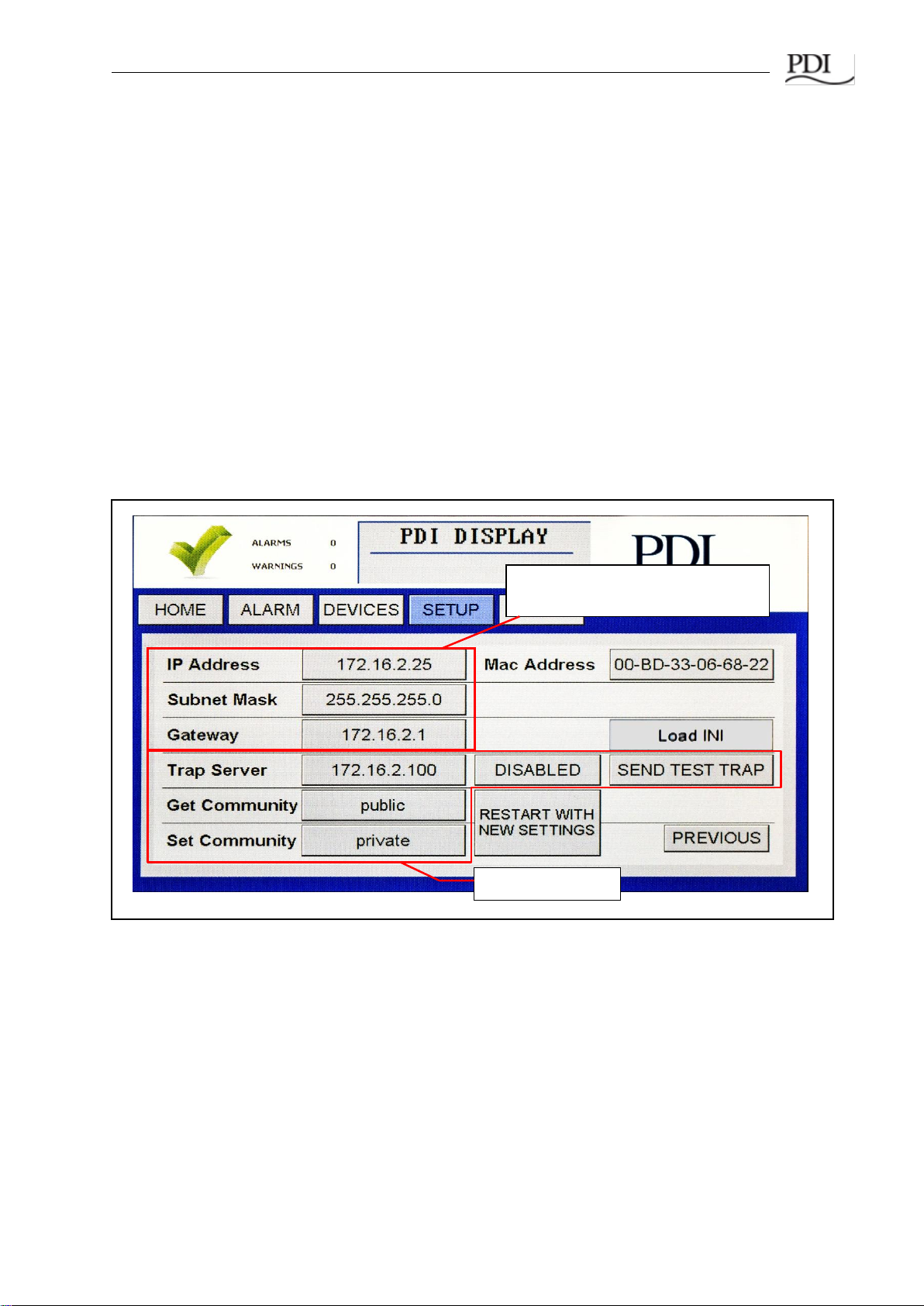
3.2.3 TCP/IP and Modbus TCP/IP Setup
For TCP/IP, the customer must provide an Ethernet cable connected to the Ethernet port (RJ45
header J11) on the Monitor. (See Figure 4, “Color Monitor Network Connections”.)
On the SETUP screen, touch NETWORK/SNMP to display the network parameters for TCP/IP
(Figures 11, 14)).
The following must be specified for Modbus TCP/IP:
oIP Address
oSubnet Mask
oGateway
Each connected monitor must be assigned a unique address. DHCP is not supported.
Touch RESTART WITH NEW SETTINGS if any parameter is changed on this screen. The processor
will reboot and search the network for connections.
Figure 14 Modbus TCP/IP and SNMP Setup
3.2.4 SNMP Setup
To use SNMP, the customer must connect an Ethernet link to the RJ45 header J11 (see Figure 4) on
the Monitor using a standard Ethernet cable.
For SNMP setup, on the SETUP screen, touch NETWORK/SNMP to display the network parameters
for SNMP (Figures 11, 14).
In addition to the TCP/IP specification, the following must be specified for SNMP:
•Specify the Trap Server IP address
•Toggle ENABLED/DISABLED for the trap server.
TCP/IP Setup: Set for TCP/IP,
Modbus TCP/IP, and SNMP
Set for SNMP

WaveStar Color Monitor_____________________________________________________________
Ctrl Nr: PM375103 Revision: 003 20
•Touch SEND TEST TRAP to verify operation.
•Get Community security string for Get operations.
•Set Community security string for Set operations.
Touch RESTART WITH NEW SETTINGS if any parameter is changed on this screen. The processor
will reboot and search the network for connections.
3.2.5 Loading INI Parameters from an SD Card
Touching Load INI loads configuration parameters from an SD card inserted into the Monitor. This
function makes it easy to initialize a set of Monitors using common parameters. It is intended for
manufacturing and service use.
3.3 Software Versions
The SOFTWARE VERSIONS list (Figure 15) lists information about software levels for the Monitor
and its device chain and a customer-specified model number for the unit in which the Monitor is
installed, such as a PDU or RPP. The list has no configuration use: it does not have parameters that
determine Monitor operation.
•MODEL number: Touch MODEL and enter model number with the pop-up keyboard.
On HOME screen, touch the SOFTWARE
VERSIONS button to display a scrollable list of
versions levels for the Monitor and devices in its
device chain.
Device version numbers are customer-specifiable
IDs, intended as device software version numbers.
Specify these in the VERSION field of
DEVICESDEVICESETTINGS screen.
(See
Chapter 3, Device Chain: Settings
.)
Color Monitor (Display) software
VERSION number, from onboard
software
MODEL is intended as a customer-
specifiable ID identifying the unit in which
the Monitor is installed, such as “PDU 182”.
Touch MODEL to enter the model number:
A keyboard appears requesting the
password (Enter “VNUP”).
If password is accepted, a second
keyboard appears asking you to enter the
model number.
Figure 15 Model Information
This manual suits for next models
1
Table of contents
Other PDi Monitor manuals


