PDK RDRBT User manual

Touch io Reader
Part Number: RDRBT
Ver: 20191108

Touch io Instruction Manual
Safety, Maintenance, & Operational Information 5
Liability 5
Intellectual Property Rights 5
Equipment 5
Trademark Acknowledgments 6
Regulatory Information 6
Safety 6
Equipment Disposal and Recycling 6
Support / Sales 6
Learn More 7
Notice 7
Introduction 7
Touch io Reader 8
Theory of Operation 8
Unlimited Mobile Credentials 10
Mobile Credential Management 10
Wiegand Format 10
Touch io Features 10
Additional Listed System Components 11
Installation Features 11
Touch io Specifications 12
Power Requirements 12
Voltage Requirements 12
Current 12
Grounding 12
Wire / Cable Connection 13
Page 2

Touch io Instruction Manual
Operating Temperature 13
Audio 13
Dimensions 13
UL 294 Performance Levels 13
Access Control Factors 13
Supported Mobile Devices 14
Touch io Wiring & LED Color Indicators 15
Wiegand Wiring Colors & Functions 17
Touch io LED Colors 18
Touch io Hardware 19
Touch io Mounting Suggestions 19
ADA Mounting Requirements 20
Tools Required for touch io Installation 20
Mullion Mounting 21
Single-Gang Mounting 25
Issuing pdk.io Credentials 30
Permissions / Roles 30
Reporter 30
Manager / Admin / Integrator 30
Cloud Node Edit from Smart Device 33
Configuring touch io Reader and Doors 33
Organization 33
User Access to the Organization 34
Touch App Configurations 34
Inside/Out Technology 34
Apple Devices 35
Android Devices 35
touch App 36
Page 3

Touch io Instruction Manual
PDK.io App 36
Requesting & Accepting touch App Credentials 37
MOBILE Tab - touch App 37
Connecting to a touch io Reader 38
PAIR touch Button 40
CHECK FOR UPDATE Button 42
SETTINGS Button 43
Inside/Out Detection 43
Backlight 43
Card Type 44
FSK 44
ASK 44
Range 44
Changing Touch io Settings 45
Mobile Devices and Software 46
Removing a Credential 46
Performing a Firmware Update 46
Closing the pdk touch App - Android 48
Closing the pdk touch App - Apple 49
Performing a touch io Reset 49
Soft Reset 49
Factory Reset 50
Questions / Troubleshooting 51
Frequently Asked Questions 51
Known Issues 55
Certifications 56
Technical Support 56
Copyright 56
Page 4

Touch io Instruction Manual
Safety, Maintenance, & Operational Information
This manual is intended for trained and authorized installers of ProdataKey access control products. PDK
Cloud Nodes require firmware version 1.6.4.
Updated versions of this document will be posted to the ProdataKey website, as required. Other user
manuals are also available on the ProdataKey website’s Document Library.
https://www.prodatakey.com/documentation (ProdataKey web site > Partners > Partner Portal >
Documentation)
In this manual, ProdataKey and its door controllers are referred to as the PDK products, single io, eight io,
product, network door controller, device, device controller, and Cloud Node.
Liability
Every care has been taken in the preparation of this document. Please feel free to inform ProdataKey
Support of any inaccuracies or omissions in this documentation. We welcome your feedback and
suggestions. ProdataKey cannot be held responsible for any technical or typographical errors and reserves
the right to make changes to the product and manuals without prior notice.
ProdataKey makes no warranty of any kind with regard to the material contained within this document,
including, but not limited to, the implied warranties of merchantability and fitness for a particular purpose.
ProdataKey shall not be liable nor responsible for incidental or consequential damages in connection with
the furnishing, performance, or use of this material. This product is only to be used for its intended purpose.
Intellectual Property Rights
Patents Pending - ProdataKey has intellectual property rights relating to technology embodied in the
product described in this document.
Equipment
This equipment must be installed and used in strict accordance with the instructions given in the user
documentation. This equipment contains no user-serviceable components. Wiring methods shall be in
accordance with the National Electrical Code, ANSI/NFPA 70. Unauthorized equipment changes or
modifications will invalidate all applicable regulatory certifications and approvals.
Use only accessories that comply with the technical specification of the product. These can be provided by
ProdataKey or an approved third party. Use only spare parts provided by or recommended by ProdataKey.
After the system is installed and working properly, no further maintenance or testing is required.
Page 5

Touch io Instruction Manual
Do not attempt to repair the product by yourself. Contact ProdataKey Support or your ProdataKey
authorized distributor for service matters.
Trademark Acknowledgments
ProdataKey, prodatakey, PDK, Prodata, are registered trademarks or trademark applications of ProdataKey
in various jurisdictions. All other company names and products are trademarks or registered trademarks of
their respective companies. Permission to use, copy, modify, and distribute this software and its
documentation for any purpose with or without fee is hereby granted, provided that the copyright notice
appears in all copies and that both the copyright notice and this permission notice appear in supporting
documentation.
Regulatory Information
Electromagnetic Compatibility (EMC)
This equipment has been designed and tested to fulfill applicable standards for:
●Radio frequency emissions when installed according to the instructions and used in its intended
environment.
●Immunity to electrical and electromagnetic phenomena when installed according to the instructions and
used in its intended environment.
Safety
This manual has been prepared to help you install the product. Read through the installation instructions
carefully before installing the product. Keep the guide for future installation and maintenance reference.
This product complies with IEC/EN/UL 60950-1, Safety of Information Technology Equipment. If your
connecting cables are routed outdoors, the product shall be grounded either through a shielded network
cable (shielded twisted pair) or another appropriate method.
The power supply used with this product shall fulfill the requirements for Safety Extra Low Voltage (SELV)
and Limited Power Source (LPS) according to IEC/ EN/UL 60950-1.
Equipment Disposal and Recycling
When this product has reached the end of its useful life, dispose of it according to local laws and regulations.
For information about your nearest designated collection point, contact your local authority responsible for
waste disposal. In accordance with local legislation, penalties may be applicable for incorrect disposal of this
waste.
Support / Sales
Support:
Page 6

Touch io Instruction Manual
Phone: 801.317.8802 option #2 or call direct at: 801.206.4086 and 801.871.3009
Email: support@prodatakey.com
Sales:
Phone: 801.317.8802 option #1
Email: sales@prodatakey.com
●You can research questions and queries from the ProdataKey website https://www.prodatakey.com
●Download user documentation and software updates at https://www.prodatakey.com/dealer-portal
●Contact Support staff (North America only) at https://www.prodatakey.com/contact
Learn More
Visit ProdataKey learning center https://www.prodatakey.com/training-schedule for certification trainings
and events, webinars, and tutorials.
Notice
●The ProdataKey Single io and Eight io door controllers are intended for indoor use only.
●The ProdataKey product shall be used in compliance with local laws and regulations.
●The ProdataKey product shall be installed within a secured area.
●Mount in a dry and well-ventilated environment.
○To provide the best conditions and proper operation of the product, the controller must be securely
mounted in accordance with the installation instructions.
●Use only applicable tools when installing the ProdataKey product. Using excessive force while mounting
the product could cause damage.
●Avoid exposing any ProdataKey product to shocks or heavy pressure.
●Use only accessories that comply with the technical specification of the product. These can be provided
by ProdataKey or a ProdataKey authorized third-party vendor.
●Do not attempt to repair the product by yourself. Contact ProdataKey support or your ProdataKey
authorized distributor for service matters.
●For UL certified installations, all cable runs to the door controllers must be less than 98.5 ft. (30 meters).
Introduction
The touch io reader provides a simple and convenient way to leverage state-of-the-art Bluetooth Low
Energy (BLE) mobile credentials for access control. Whether it’s a new site installation or an upgrade to an
existing system, realizing the power of touch io mobile credentials is a simple process.
Page 7

Touch io Instruction Manual
Touch io is the brand name ProdataKey has created for the Bluetooth Low Energy-based mobile credential
reader, cloud-based credential management and issuance service, and smartphone applications.
Touch io gives customers smarter access to facilities, granting them more control over who has access and
when through an intelligent credential sharing system. Permissioned users can share and revoke access at
any time, from any remote location, using a smartphone or tablet.
Enjoy keyless access with the touch io reader mobile credentials. Create new mobile solutions or bring
legacy readers online with the touch io product offering. It is no longer necessary to sacrifice convenience
for security. Bring Physical Access Control Systems (PACS) up to date with the latest in mobile key
technology and eliminate the necessity to carry keys, cards, or fobs for secure access. When you download
and install the touch App to your mobile device for use with touch io readers you’ll enjoy seamless, key-free
access through exclusive features like Inside/Out Technology. Using Bluetooth Low Energy (BLE)
technology, users can simply present their phone as they would a key card or fob, or leave it in their pocket
to gain access to secured doors.
The touch io reader is simple to use and handles both legacy and Bluetooth credential support without
compromise to the user experience. Whether it’s a 30-year-old security system or one that’s yet to be built,
the touch io platform can be seamlessly integrated into any piece of access control technology.
For Bluetooth Low Energy credential support, the phone can stay in your pocket or purse; no need to open
an app and press Enter. And no need to make a “knob-turning” gesture with the phone.
NOTE: This reader requires a PDK system with an annual subscription to operate. Visit https://www.prodatakey.com to
learn about pdk.io and our complete lineup of access control products.
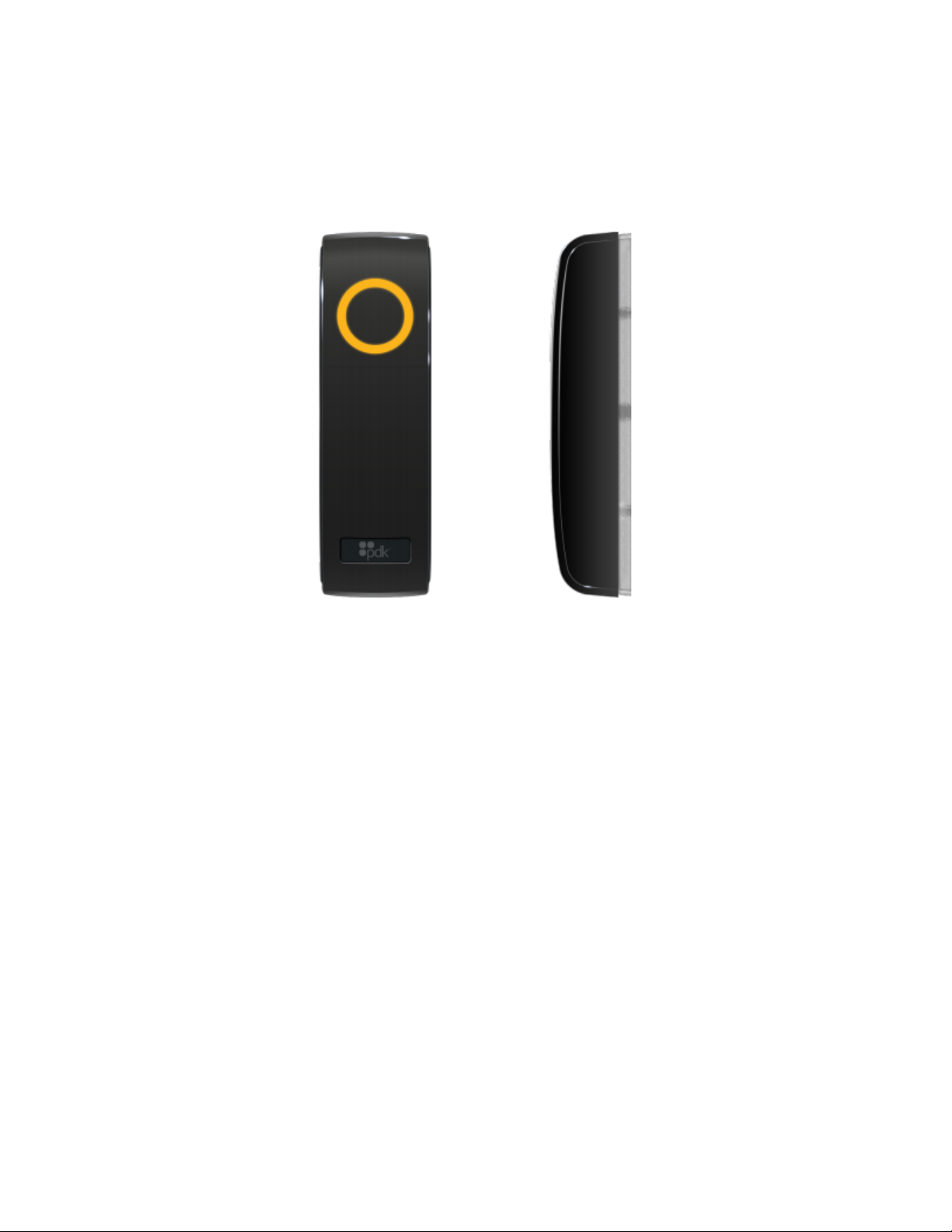
Touch io Reader
Touch io offers unparalleled convenience and security. By using a mobile device as a credential, touch io
allows users to keep their phone in their pocket or purse for hassle-free entry. Simply tap the reader, and
touch io will automatically authenticate or deny access. Unlike other Bluetooth readers, touch io uses
Inside/Out Technology to prevent accidental and unauthorized openings. Using advanced hardware, the
reader detects which side of the door a user is standing, distinguishing between credentials inside or outside
a room before granting access.
The touch io reader is the physical hardware that supports a mullion style or single-gang style mounting
installation. Touch io uses standard 26- to 37-bit Wiegand formats and supports legacy 125KHz prox cards
and fobs, as well as the proprietary ProdataKey touch App credential. The touch io may be configured
during installation or at any time using the touch App and provides a simple and convenient way to leverage
BLE mobile credentials for access control.
NOTE: Standard RFID credentialed prox cards and key fobs are not as secure as using a smart device for
touch io access. Standard legacy prox cards can be cloned easily. The touch App is designed for
convenience, ease of use, and greater security.
Theory of Operation
Touch io is an access control hardware device that stands as one part of an access control system to manage
personnel entry into and out of buildings and its interior doors. The touch io reader utilizes mobile device
Page 8

Touch io Instruction Manual
cloud service credential management for both Bluetooth Low Energy and legacy reader capability. It
provides for access control from a single application on any Internet-enabled mobile or desktop device. An
Internet or Wi-Fi connection is not required on the mobile device when being utilized for credential use. The
cloud service is merely used for easy and fast issuance and management of credentials.
Atouch io reader is associated with an organization’s pdk.io door controller and can be paired to a user’s
phone or other smart device. The user’s touch io credentials are presented to the reader and passed along to
the access control system for validation. If the access request is valid, the touch io reader displays the
designated LED color and entrance is granted at that reader access point.
IMPORTANT: A ProdataKey Cloud Node is required to operate the touch io readers.
For Bluetooth-supported smartphone credential support, with the phone in your pocket or purse, just touch
the reader. An existing standard legacy proxy card or key fob credential can also be used; all that is
necessary is to present the card or fob for access.
Touch io is designed for the ease of users using the pdk.io App and the touch App. The pdk.io App is for
anyone with Integrator, Admin, or Manager (also referred to as an administrator) permission roles to
provision and configure touch io readers. The touch App can be used by anyone who has been granted
access to a system.
NOTE: Multiple smart devices may be added to access the touch io door controllers; the same credential
invitation, however, cannot be used for accepting another device. An additional credential must be
sent to a user and accepted in order to add an additional device.
Users experience a new level of convenience to gain entry to a protected area as their Bluetooth-enabled
smartphone becomes a mobile credential for touch io readers, eliminating the need to carry or worry about
a lost fob or prox card.
NOTE: Readers that are NOT Bluetooth enabled will still require either a traditional credential (such as a
prox card) or the touch App credential.
The touch App runs silently in the background of the user’s mobile device, transmitting the BLE credential to
the reader when the user activates the reader’s capacitive touch sensor by touching the reader.
NOTE: Standard RFID credentialed prox cards and key fobs are not as secure as using a smart device for
touch io access. Standard legacy prox cards can be cloned easily. The touch App is designed for
convenience, ease of use, and greater security.
The touch App that transmits the credential to the reader uses very little power and merely needs to be
running in the background; an Internet or Wi-Fi connection on the mobile device is not required for reader
access when being utilized for credentialed access. The cloud service is merely used for easy and fast
issuance and management of credentials. Internet access is only needed to download the app and accept the
credentials that have been issued. Once accepted, credentials are securely stored on the smartphone.
Page 9

Touch io Instruction Manual
Unlimited Mobile Credentials
With touch io, you can issue an unlimited number of mobile credentials per reader. There’s no need to buy
redeemable scratch cards, and system owners will experience significant cost savings over traditional access
control cards.
Mobile Credential Management
Unlike traditional prox cards, mobile credentials are nearly impossible to copy or clone, and a lot less likely
to become lost or stolen. In addition, administrators (any user with an Integrator, Admin, or Manager
permission role) can easily add or delete employee mobile credentials with just a few clicks in the pdk.io App
or in the pdk.io website.
Wiegand Format
The standard 26- to 37-bit Wiegand format is an open format; it is a widely-used industry standard. Almost
all access control systems accept the standard 26-bit format which consists of two parity bits, 8-bit facility
code, and 16-bit card number fields. The Wiegand interface is commonly used to connect a card swipe
mechanism to the rest of an access control system. The physical size limitations of the card dictates that a
maximum of 37 Wiegand wire filaments can be placed in a standard card before misreads affect reliability;
therefore, most Wiegand formats used in physical access control are less than 37 bits in length.
Touch io Features
●The Bluetooth Low Energy-compatible reader utilizes BLE version 4.0 and supports modern mobile
devices and prox cards.
●Unlimited mobile credentials
●RFID (Radio Frequency Identification) Proximity 26- to 37-bit Wiegand-based 125KHz pass through of
bit length
●Touch-to-access, or touch-to-open. With the phone in your pocket or purse, touch the reader and the
door unlocks.
●Sophisticated military grade and best-in-class security with Public Key Infrastructure (PKI) architecture
to encrypt credentials in the cloud and directly at the door
●Inside/Out Detection technology
●ISOProx II (HID Prox II H10301 compatible FSK modulations*)
●EM4102 (ASK modulations)
●RGB backlit LED ring for user feedback
Page 10

Touch io Instruction Manual
●Electronics potted and sealed with tamper-resistant epoxy for indoor and outdoor installation
●Water resistant IP65** (IP rated as "dust tight" and protected against water projected from a nozzle.)
●FCC, RoHs, UL Standard 294
●5KHz audio buzzer
* FSK (Frequency-Shift Keying) is a method of transmitting digital signals. FSK has several advantages over ASK due to the fact that
the carrier has a constant amplitude.
** The IP Code classifies and rates the degree of protection provided by mechanical casings and electrical enclosures against
intrusion, dust, accidental contact, and water. The first number is for solids protection such as dust; it ranges from 0 to 6. The
second number is for the part's protection against liquids; it ranges from 0 to 8.
Additional Listed System Components
Cloud Node
●Provides unlimited cardholders, years of event storage, battery backup, and auto
data backup.
●Cloud Node Part Number: CN
●Cloud Node Server Edition Part Number: SVR
Single io
●Run controls for multiple doors and/or build a larger network. Also used for legacy
system change-out.
●Wireless Part Number: 1DW
●Ethernet Part Number: 1DE
●Power Over Ethernet Part Number: 1DPOE
Eight io
●Run controls for multiple doors and/or build a larger network. Also used for legacy
system change-out.
●Pro Wireless Part Number: 8DW
●Ethernet Part Number: 8DE
Proximity Reader
Must be UL 294 listed
Proximity Credentials
Must be UL 294 listed
Electronic Locking Hardware
Must be UL 294 listed
Installation Features
●One-time enrollment of the reader to the cloud allows for an unlimited number of mobile credentialed
users to access the reader.
●Existing presets for power and LED animation provide for an easy setup, and immediately ready to use.
Page 11

Touch io Instruction Manual
●An adjustable Bluetooth Low Energy range provides for flexibility in the level of security. (See Range for
additional information.)
Touch io Specifications
This manual walks anyone having an administrator permission role through the steps needed to connect a
touch io reader to an access control panel. In addition to smartphone touch io mobile credentials and use of
the touch App,touch io also supports 125KHz prox cards. Reviewing and following the information below
ensures the reader is installed quickly and properly.
NOTE: Standard RFID credentialed prox cards and key fobs are not as secure as using a smart device for
touch io access. Standard legacy prox cards can be cloned easily. The touch App is designed for
convenience, ease of use, and greater security.
Power Requirements
●5.5 to 16VDC. A 12VDC regulated power supply is recommended for best operation.
●When the Backlight is off (low power mode), the reader uses 100mA to 200mA at 12VDC.
●When the Backlight is on (high power mode), the reader uses a maximum of 350mA at 12VDC.
●A regulated non-switching 12VDC power supply at the panel is recommended to power the touch io
reader for the best performance and highest noise immunity.
●For UL 294 compliance, the reader MUST be connected to a class-two power-limited power supply or
control panel output.
●24 AWG wire is recommended
Voltage Requirements
●12VDC is recommended. Minimum voltage required is 5.5VDC to a maximum of 16VDC.
●Touch io requires 100mA - 200mA (at 12VDC) in low power mode (Backlight off), 350mA maximum (at
12VDC) in high power mode (Backlight on). By default, the Backlight is on; mode settings are configured
via the touch App.
Current
100mA - 200mA (low power) typical at 12VDC. 350mA (high power) maximum peak at 12VDC
Grounding
The cable shielding* must run continuously from the reader to the panel. At the panel end, the reader
ground, shield line, and earth ground MUST be connected together at a single point. At the reader end DO
NOT ground the shield line as this creates a potential ground loop.
* Data and signal cables are usually protected with insulated conductors and wrapped with a conductive (metallic) shielding layer. This
shielding reduces electrical noise and its impact on signals and lowers electromagnetic radiation. Shielding is needed to combat the
Page 12

Touch io Instruction Manual
effects of electromagnetic interference (EMI). Without shielding, cables can be a main source for transfer of EMI, both as a source and
as a receiver. (As a source, the cable can conduct electrical noise to other equipment or act as an antenna radiating electrical noise. As a
receiver, the cable can pick up EMI being radiated from other sources.)
Wire / Cable Connection
●Connections MUST be in accordance with NFPA 70. DO NOT connect to a receptacle controlled by a
switch.
●For UL certified installations, all cable runs to the door controllers must be less than 98.5 ft. (30 meters).
Operating Temperature
-40° F to 140° F (-40° C to +60° C)
Audio
5KHz buzzer
Dimensions
6 in. (H) x 1.7 in. (W) x 1.3 in. (D) / 15.24 cm (H) x 4.32 cm (W) x 3.3 cm (D)
UL 294 Performance Levels
UL 294 is the Underwriters Laboratory standard for access control system units, which is used to evaluate
the construction, performance, and operation of access control systems for factors such as destructive level,
security, endurance, and standby power. Each of these factors has four levels of performance which
evaluates the safety of the system and ensures that the products will operate reliably without creating a
hazardous condition. Level 1 establishes that the products are safe for egress purposes.
Model #
Access Control
Line Security
Destructive
Attack
Endurance
Standby
Power
Condition
RDRBT - touch io
Level 1
Level 1
Level 3
Level 1
N/A
Access Control Factors
Feature
Level 1
Level 2
Level 3
Level 4
Destructive
Attack
No attack test
required.
Can withstand an attack
for 2 minutes.
Can withstand an attack
for 5 minutes, or 2 minutes
if alarm is activated during
the test.
Can withstand an attack for 5
minutes, but shall generate an
alarm event in a maximum of 2
minutes of attack, and the alarm
shall not be silenced for another
2 minutes.
Page 13

Touch io Instruction Manual
Line
Security
No line security
required.
Standard line security
required.
128-bit line security
encryption required.
256-bit line security encryption
required.
Endurance
Must be able to
operate as intended
at rated voltage &
current for 1,000
cycles of intended
operation.
Must be able to operate
as intended at rated
voltage and current for
25,000 cycles of intended
operation.
Must be able to operate as
intended at rated voltage
and current for 50,000
cycles of intended
operation.
Must be able to operate as
intended at rated voltage and
current for 100,000 cycles of
intended operation.
Standby
Power
No secondary power
source required.
After a loss of primary
power, the system can
maintain normal
operations for a minimum
of 30 minutes while the
product is operated every
minute.
After a loss of primary
power, the system can
maintain normal
operations for a minimum
of 2 hours while the
product is operated every
2 minutes.
After a loss of primary power,
the system can maintain normal
operations for a minimum of 4
hours while the product is
operated every 5 minutes.
Supported Mobile Devices
Most Apple devices running iOS 11.0 or higher, and Android devices running Android v6.0 (Marshmallow) or
higher are supported, as long as it supports Bluetooth Low Energy (BLE) version 4.0 Peripheral Mode.
Need additional information about any of the following?
Power Requirements
Voltage Requirements
Current
Grounding
Wire/Cable Connection
Operating Temperature
Audio
Dimensions
Wiegand Reader Wiring
Wiegand Wiring Colors & Function
UL 294 Performance Levels
Touch io LED Colors
Page 14

Touch io Instruction Manual
Touch io Wiring & LED Color Indicators
For touch io and door controller wiring, the image illustrates the reader’s wiring configuration to the door
controller.
NOTE: For UL certified wire installations, all wire running from a Single io door controller to a lock, strike,
or reader device must be less than 98.5 feet (30 meters).
Touch io Reader - Mounted at the door with a 22/5 or 22/6 wire running to the door controller. Wire the
reader to the controller as shown above.
Secondary Reader - If an additional touch io reader is used, it should be mounted at a door with a 22/5 or
22/6 wire running to the controller as shown above.
Piezo (buzzer) - Optional piezo trigger wiring for a tamper or door prop alarm connects to (-) on the AUX
relay. The piezo buzzer can be controlled with software rules.
NOTE: Check polarity and voltage carefully prior to powering the controller.
Page 15

Touch io Instruction Manual
(A) AUX Device - An AUX device can be connected to the door controller to be triggered based on specified
events in the system; the most typical is a door prop alarm. The O (AUX Output) uses board power to
trigger the device so be sure correct amperage and voltage are available. If a full relay is needed, an AUX
relay can be connected to the (O) output to be triggered.
(B) NC/NO Jumper - If the device connected requires power to be triggered, then place the jumper between
the center pin and NO. If the device requires dropping power to be triggered then place the jumper
between the center and NC.
(C) +/- Jumper - If the device needs negative (-) on the trigger leg then place the jumper between the center
pin and (-). If the device needs positive (+) on the trigger then place the jumper between the center pin
and (+).
Need additional information about any of the following?
Power Requirements
Voltage Requirements
Current
Grounding
Wire/Cable Connection
Operating Temperature
Audio
Dimensions
Supported Mobile Devices
Wiegand Wiring Color & Functions
UL 294 Performance Levels
Page 16

Touch io Instruction Manual
Touch io LED Colors
Wiegand Wiring Colors & Functions
Wire Conductor
Function
Red - Power to +(positive) connector
DC Power +12VDC
Black - Power to -(negative) connector
Ground (-)
Green - To D0 (data zero) connector
Data 0 (zero)
White - To D1 (data 1) connector
Data 1
Blue - To LED connector (Required) On ground, continuously on.
Green LED
Orange - To O(Aux) connector (Optional)
Piezo Buzzer (C)
Yellow -Optional connector
Card Present
Purple - To LED connector (Optional) On ground, continuously on.
Red LED
Orange - Beep. On ground, continuously on.
Shielded Drain -Optional but HIGHLY suggested as an additional ground*
Shielded Ground (-)
Restaurant Menu
Current Draw: 100mA - 200mA (typical at 12VDC) in low power mode; 350mA maximum in high power mode.
*NOTE: Data and signal cables are usually protected with insulated conductors and wrapped with a
conductive (metallic) shielding layer. This shielding reduces electrical noise and its impact on
signals and lowers electromagnetic radiation. Shielding is needed to combat the effects of
electromagnetic interference (EMI). Without shielding, cables can be a main source for transfer of
EMI, both as a source and as a receiver. (As a source, the cable can conduct electrical noise to other
equipment or act as an antenna radiating electrical noise. As a receiver, the cable can pick up EMI
being radiated from other sources.)
Need additional information about any of the following?
Power Requirements
Voltage Requirements
Current
Grounding
Wire/Cable Connection
Page 17

Touch io Instruction Manual
Operating Temperature
Audio
Dimensions
Supported Mobile Devices
Wiegand Reader Wiring
UL 294 Performance Levels
Touch io LED Colors
Touch io LED Colors
Each touch io color ring code corresponds with a specific response from the reader.
Ring Color
Touch io Indication
White
Unconfigured. Going through power-up booting process / factory reset.
Yellow
Connected to power but not enrolled to organization or users.
Properly enrolled and idle; waiting for access attempt.
Yellow Spin
An access attempt has been made and reader is processing
Green
Successful credential read / access allowed
Red Flash
Access denied to the entry attempt
If you have any questions or need help with installation or with any of the hardware described in this manual,
please feel free to contact the ProdataKey Technical Support staff.
Need additional information about any of the following?
Power Requirements
Voltage Requirements
Current
Grounding
Wire/Cable Connection
Operating Temperature
Audio
Page 18

Touch io Instruction Manual
Dimensions
Supported Mobile Devices
Wiegand Wiring Colors
Wiegand Reader Wiring
UL 294 Performance Levels
Touch io Hardware
The touch io reader must be installed as part of the pdk.io cloud-based access control system. If it’s an
existing system, installing the new reader is a simple matter of removing the old reader and replacing it with
the touch io reader, using the same wiring. Once it is installed and wiring is connected, the reader displays a
yellow ring, indicating that setup with the mobile credentials is required. An existing prox card or key fob
from the old reader can be used immediately without any additional configuration.
NOTE: Standard RFID credentialed prox cards and key fobs are not as secure as using a smart device for
touch io access. Standard legacy prox cards can be cloned easily. The touch App is designed for
convenience, ease of use, and greater security.
Need additional information about any of the following?
Inside/Out Technology
Suggestions for Mounting
ADA Mounting Requirements
Touch io Mounting Suggestions
●If the touch io reader is used to control a door or pedestrian gate, locate the unit as near to the entry
point as practical.
●If the reader unit is mounted on a wall adjacent to the entry point, be sure the wall is a suitably sturdy,
flat surface. The repeated shock and vibration from a slamming access door or spring-loaded pedestrian
gate MUST be isolated from the unit.
●Never mount the touch io reader directly on a moving door or gate.
●Choose a well-lit location near the controlled opening.
●Wiring access for power, network, and earth ground MUST be available to the mounting location.
●Touch io supports both single-gang and mullion-mount installations and is suitable for both indoor and
outdoor use.
Need additional information about any of the following?
ADA Mounting Requirements
Page 19

Touch io Instruction Manual
Required Installation Tools
Mullion Mounting
Single-Gang Mounting
ADA Mounting Requirements
The Americans with Disabilities Act has certain height and reach requirements to allow access for persons in
wheelchairs.
●In locations where wheelchair access is only available from the front, keypads and readers should be
mounted so the top of the touchpad is no more than 48” (122 cm) above the finished floor, with no
obstructions.
●In locations where the wheelchair has sideways access, keypads and readers should be mounted so the
top of the touchpad is no more than 54” (137 cm) above the finished floor, with no obstructions.
Need additional information about any of the following?
Touch io Mounting Suggestions
Required Tools for touch io Installation
Mullion Mounting
Single-Gang Mounting
Tools Required for touch io Installation
Assuming a fresh install, or even for modifications to an existing system, some or all of the following tools
will be needed to mount, install, and connect the touch io to a door controller. The necessary bracket(s),
mounting screws, and wall anchors (if needed) are provided with the touch io reader package.
●Power drill & drill bit(s) for mounting screws or #2 Phillips screwdriver
●Drill bit for patch antenna wire (long enough to pass through the mounting wall)
●Low-voltage white B wire splice connectors
●Wire Cutter/Crimping tool
●Electrical Tape
●Pencil (to mark hole positions on the mounting surface)
If the touch io is to be mounted to a metal mullion or a similarly hard surface, an appropriate sized drill bit
will be needed for the bracket’s mounting holes as well as a hole large enough for the reader and door
controller wires to pass through.
Need additional information about any of the following?
Page 20
Table of contents