Peak Electronics DCA75 User manual

Peak Atlas DCA Pro
Advanced Semiconductor Component Analyser
with Graphics Display and PC connectivity
Model DCA75
Designed and manufactured with pride in the UK
User Guide
©
Peak Electronic Design Limited 2012/201
In the interests of development, information in this guide is subject to change without notice - E&OE
GB7 -1.4

Atlas DCA Pro User Guide April 2015 – Rev 1.4
Page 2
Want to use it now?
We understand that you want to use your Atlas DCA Pro right now.
he unit is ready to go and you should have little need to refer to this
user guide, but please make sure that you do at least take a look at the
notices on page 5.
Contents Page
Introduction....................................................................................4
Important Considerations...............................................................5
Analysing Semiconductors - Standalone mode..............................6
Diodes......................................................................................8
Zener Diodes............................................................................9
Diode Networks.....................................................................10
LEDs......................................................................................11
Bicolour LEDs (2-lead types) ................................................12
Bicolour LEDs (3-lead types) ................................................13
Bipolar Junction ransistors (BJ s).......................................14
Darlington ransistors ...........................................................18
Enhancement Mode MOSFE s .............................................21
Depletion Mode MOSFE s ...................................................22
Enhancement Mode IGB s....................................................23
Depletion Mode IGB s..........................................................24
Junction FE s (JFE s) ..........................................................25
hyristors (SCRs) and riacs.................................................27
Voltage Regulators ................................................................28
Contents continued on next page…

Atlas DCA Pro User Guide April 2015 – Rev 1.4
Page 3
Contents (continued) Page
PC Software Installation............................................................29
Windows XP Installation .......................................................30
Windows Vista, 7 and 8 Installation ......................................31
Running the DCA Pro software for the first time ........................32
Analysing Semiconductors – PC mode........................................33
PC mode - Curve racing functions.......................................34
PC mode - Exporting your data..............................................35
PC mode - Special functions..................................................36
Audible Settings...........................................................................37
Care of your Atlas DCA Pro........................................................38
Self est Procedure ......................................................................39
Appendix A - roubleshooting ....................................................40
Appendix B - echnical Specifications........................................41
Appendix C - Analysis test circuits..............................................43
ransistor test circuit .............................................................43
JFE /MOSFE /IGB test circuit..........................................44
Diode test circuit....................................................................45
Voltage regulator test circuit..................................................46
Appendix D - Warranty Information............................................47
Appendix E - Disposal information .............................................47

Atlas DCA Pro User Guide April 2015 – Rev 1.4
Page 4
Introduction
he Peak Atlas DCA Pro is an advanced semiconductor analyser that
combines simplicity, ease of use and a range of advanced features. You can use
your DCA Pro on its own or in combination with a laptop or desktop PC.
Summary Features:
• Automatic component type identification and schematic display:
Bipolar transistors.
Darlington transistors.
Enhancement Mode and Depletion Mode MOSFE s.
Enhancement Mode and Depletion Mode IGB s.
Junction FE s.
Low power sensitive riacs and hyristors.
Light Emitting Diodes.
Bicolour LEDs.
Diodes and Diode networks.
Zener diodes.
Voltage regulators.
• Automatic pinout identification, just connect any way round.
• Special feature identification such as free-wheeling diodes and
resistor shunts.
• Gain measurement for bipolar transistors.
• Leakage current measurement for bipolar transistors.
• Silicon and Germanium detection for bipolar transistors.
• Gate threshold measurement for Enhancement Mode MOSFE s.
• Semiconductor forward voltage measurement for diodes, LEDs and
transistor Base-Emitter junctions.
• Zener voltage measurement.
• PC connectivity providing:
Larger component identification display.
Detailed characteristics measurement.
Curve tracing functions.
• Single alkaline AAA battery (not used when USB connected).
• Automatic and manual power-off.

Atlas DCA Pro User Guide April 2015 – Rev 1.4
Page 5
Important Considerations
Please observe the following guidelines:
•
his instrument must NEVER be connected to powered
equipment/components or equipment/components with any
stored energy (e.g. charged capacitors). Failure to comply
with this warning may result in personal injury, damage to
the equipment under test, damage to your DCA Pro and
invalidation of the manufacturer’s warranty.
•
he DCA Pro is designed to analyse semiconductors that
are not in-circuit, otherwise complex circuit effects will
result in erroneous measurements.
•
Avoid rough treatment, hard knocks and extreme
temperatures.
•
his unit is not waterproof.
•
Only use a good quality AAA Alkaline battery.

Atlas DCA Pro User Guide April 2015 – Rev 1.4
Page 6
Testing...
Analysing Semiconductors – Standalone mode
he DCA Pro is designed to analyse discrete,
unconnected, unpowered components. his
ensures that external connections don’t
influence the measured parameters. he three
test probes can be connected to the component any
way round. If the component has only two terminals, then
any pair of the three test probes can be used.
he DCA Pro will start component analysis when the on-test button is
pressed.
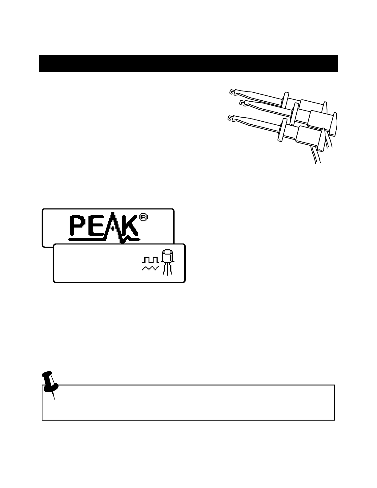
For the first analysis (after the unit has
been switched off) the tests are
performed while displaying the Peak
logo.
For subsequent testing when the unit
is already powered-up, the unit
displays the “Testing…” screen.
Depending on the component type, analysis may take a few seconds to
complete, after which, the results of the analysis are displayed.
Information is displayed a “page” at a time, each page can be smoothly scrolled
by briefly pressing the scroll-off button.
Although the DCA Pro will switch itself off if left unattended, you
can manually switch the unit off by holding down the scroll-off
button for a couple of seconds.

Atlas DCA Pro User Guide April 2015 – Rev 1.4
Page 7
No component
detected.
Unknown/faulty
component.
Red & Blue
leads shorted.
Red, reen & Blue
leads shorted.
If the DCA Pro cannot detect any
component between any of the test
probes, the following message will be
displayed:
If the component is not a supported
component type, a faulty component or
a component that is being tested in-
circuit, the analysis may result in the
following message being displayed:
Some components may be faulty due to
a shorted junction between a pair of the
probes. If this is the case, the following
message (or similar) will be displayed:
If all three probes are shorted (or very
low resistance) then the following
message will be displayed:
It is possible that the DCA Pro may detect one or more diode
junctions or other component type within an unknown or faulty part.
his is because many semiconductors comprise of PN (diode)
junctions. Please refer to the section on diodes and diode networks for
more information.

Atlas DCA Pro User Guide April 2015 – Rev 1.4
Page 8
Diode junction
reen-K Blue-A
VF
=0.694V at 5.00mA
Diodes
he
DCA Pro will analyse almost any type of diode. Any
pair of the three test clips can be connected to the diode, any way
round. If the unit detects a single diode, a message similar to the following
will be displayed:
In this example, the Cathode (symbol of
K) is connected to the Green test clip
and the Anode (symbol of A) is
connected to the Blue test clip,
additionally, the Red test clip is unconnected.
he forward voltage drop is also displayed; this gives an indication of the
diode technology. In this example, it is likely that the diode is a standard
silicon diode. A germanium or Schottky diode may yield a forward voltage of
about 0.25V. he current at which the diode was tested is also displayed. he
DCA Pro typically tests diodes (PN junctions) at a forward current of 5mA.
Note that the DCA Pro will detect only one diode even if two diodes
are connected in series when the third test clip is not connected to the
junction between the diodes. he forward voltage drop displayed
however will be the voltage across the whole series combination.
he DCA Pro will determine that the diode(s) under test is an LED if
the measured forward voltage drop exceeds 1.50V. Please refer to the
section on LED analysis for more information.

Atlas DCA Pro User Guide April 2015 – Rev 1.4
Page 9
Zener diode
Red-K Blue-A
VR
=5.094V at 5.00mA
Red-K Blue-A
VR
=5.094V at 5.00mA
VF
=0.702V at 5.00mA
Zener Diodes
he DCA Pro supports Zener diodes (and Avalanche
diodes). Additionally, the instrument can measure the Zener
voltage*.
Connect any pair of the 3 test leads to the Zener diode.
Following analysis, the component
details are displayed.
In this example, a Zener diode with a
reverse voltage (Zener voltage) of
nearly 5.1V has been detected.
Additionally, the forward biased
voltage characteristic is measured, 0.702V at 5mA for this example.
he DCA Pro attempts to test the Zener diode with a current of nominally
5mA. For Zener diodes with a Zener voltage of more than about 9V, a lower
test current will be used. his is illustrated in the following graph:
0
1
2
3
4
0 1 2 3 4 6 7 8 9 10 11 12
Zener Voltage Volts)
Test Current mA)
* he DCA Pro may not be able to identify Zener diodes with a Zener voltage
of more than 11V. It will however still identify the diode junction in its
forward biased mode.

Atlas DCA Pro User Guide April 2015 – Rev 1.4
Page 10
2 diode junctions
#1: Diode junction
reen-K Blue-A
#1: Diode junction
reen-K Blue-A
VF=0.699V at 5.00mA
#2: Diode junction
Red-A Blue-K
VF=0.683V at 5.00mA
Diode Networks
he DCA Pro will identify multiple diode junctions
between the probes. For three terminal devices such as
SO -23 diode networks, all three test clips must be
connected.
he instrument will show the results for each diode junction in turn.
Firstly, the unit will show that it has
found a number of diode junctions:
he details for the first diode are then
displayed (Diode #1). In this example,
the Green test clip is on the Cathode of
diode #1 and the Blue test clip is on the
Anode.
he details for the second diode are
then displayed (by briefly pressing
scroll-off):
It can be seen in the above example, that the blue test clip is connected to both
the anode on Diode #1 and to the cathode of Diode #2. his means that the two
diodes are effectively connected in series, with the blue clip at the mid point.
his example is illustrated below:
#1
Green Red
Blue
#2
In the same way as the single diode analysis, the forward voltage for each
diode is measured for a nominal test current of 5mA.

Atlas DCA Pro User Guide April 2015 – Rev 1.4
Page 11
LED
Red-K Blue-A
VF
=1.962V at 5.00mA
LEDs
An LED (light emitting diode) is really just another type of
diode, however, the DCA Pro will determine that an LED or
LED network has been detected if the diode’s measured
forward voltage drop is larger than 1.5V. his also enables the
DCA Pro to intelligently identify bicolour LEDs, both two-lead
and three-lead varieties. See the section on bicolour LEDs for more
information.
For two leaded parts, connect any pair of the 3 test clips to your LED. Leave
the 3
rd
lead unconnected.
In this example, the Red test clip is
connected to the LED’s Cathode
(negative) and the Blue test clip is
connected to the Anode (positive).
he forward voltage of the LED is measured at a nominal current of 5mA.
During the analysis process, the LED will briefly illuminate (so you
can see it’s illumination colour). he test current of 5mA means that it
may not be as bright as you expect, LEDs are often used at currents of
10-20mA. Power LEDs are sometimes driven at 350mA or more.

Atlas DCA Pro User Guide April 2015 – Rev 1.4
Page 12
Bicolour LED (2 lead)
#1: LED
Red-K Blue-A
#1: LED
Red-K Blue-A
VF=1.823V at 5.00mA
Bicolour LEDs 2-lead types)
Bicolour LEDs are generally available in two main varieties;
2-lead and 3-lead types.
his section describes the testing of 2-lead
bicolour LEDs. hese types are internally
connected in inverse parallel (back-to-back).
Similar to the diode network analysis, each LED within the
bicolour LED is detailed in turn.
his example shows that LED #1 has
its Cathode connected to the Red test
clip and its Anode connected to the
Blue test clip. he forward bias
characteristic is shown for LED#1,
1.823V at 5mA in this example.
Pressing scroll-off then shows the
details for the 2
nd
LED in the bicolour
LED package.
As expected for 2-lead bicolour LEDs,
we can see in this example that LED#2 has its connections in exactly the
opposite configuration to LED#1.
Note that it is common for the two LEDs within a bicolour LED to
have different forward voltage characteristics. Red is often the lowest
forward voltage, progressing through amber, yellow, green and then
blue (or white) with the highest forward voltage. See the table at the
bottom of the ne t page.
#2: LED
Red-A Blue-K
VF=1.944V at 5.00mA

Atlas DCA Pro User Guide April 2015 – Rev 1.4
Page 13
Bicolour LED (3 lead)
Common Cathode
#1: LED
#1: LED
Red-A reen-K
VF=1.935V at 5.00mA
#2: LED
reen-K Blue-A
VF=1.877V at 5.00mA
Bicolour LEDs 3-lead types)
3-lead bicolour LEDs are available in
common cathode and common anode
varieties. he DCA Pro supports both types.
In the same way as the 2-lead bicolour LED
analysis, each internal LED is detailed separately on the
DCA Pro screen.
he type of bicolour LED is shown
here, in this example we have a
common cathode variety.
he details for each internal LED are
then shown.
It can be seen here that our example has
its common cathode terminal connected
to the Green test clip.
ypical values of forward voltage for LED colours are shown here:
(LED types/manufacturers may vary significantly)
LED Colour Typical V
F
@ 5mA
Red 1.81V
Amber 1.86V
Yellow 1.90V
Green (standard type) 1.95V
Green (deep green / emerald) 2.84V
Blue (and white) 2.95V

Atlas DCA Pro User Guide April 2015 – Rev 1.4
Page 14
Bipolar Junction Transistors BJTs)
Bipolar Junction ransistors are simply “conventional”
transistors, although variants of these do exist such as
Darlingtons, devices with free-wheeling diodes, resistor
shunted types and combinations of these types. All of these
variations are automatically identified by the DCA Pro and their schematic
symbol is displayed on the screen. Both NPN and PNP types are supported.
he 3 test clips can be applied to the transistor in any configuration.
As an example, testing a common
PNP transistor such as the 2N5401
will result in a display similar to this:
his example shows that the Red test
clip is connected to the Emitter, the
Green is connected to the Base and
the Blue test clip is connected to the
Collector.
Pressing scroll-off allows further details to be displayed.
he DC current gain (h
FE
), base emitter voltage drop (V
BE
) and collector
leakage current (I
C
Leak) are all shown along with their test conditions.
Refer to the following sections for more details on these measurements.
PNP Silicon BJT
Red-E reen-B Blue-C
hFE=106
hFE=106
at IC=5.00mA
VBE=0.754V
VBE=0.754V
at IB=5.00mA
IC
Leak=0.000mA

Atlas DCA Pro User Guide April 2015 – Rev 1.4
Page 15
Current Gain h
FE
)
DC current gain (h
FE
) is the ratio of the
collector current (less leakage) to the
base current for a particular operating
condition.
he DCA Pro measures h
FE
at a collector
current of nominally 5.0mA and a
collector-emitter voltage of between 3V
and 9V.
he gain of all transistors can vary
considerably with collector current,
collector voltage and also temperature.
he displayed value for gain therefore
may not represent the gain experienced at other collector currents and voltages.
his is particularly true for large devices.
he displayed value of gain is very useful however for comparing transistors of
a similar type for the purposes of gain matching or fault finding.
Darlington transistors can have very high gain values and more variation of
gain will be evident as a result of this.
he current gain of germanium transistors can vary a large amount
with changes in temperature. Even the warmth from your fingers can
alter the gain of a germanium device.
It is quite normal for transistors of the same type to have a wide range
of gain values. For this reason, transistor circuits are often designed so
that their operation has little dependence on the absolute value of
current gain.
I
C
= .0mA
I -I
(I leakage
current)
C Cleak
Cleak
hFE =
IB
IB
hFE=167
at IC=5.00mA

Atlas DCA Pro User Guide April 2015 – Rev 1.4
Page 16
VBE=0.703V
at IB=5.00mA
Base-Emitter Voltage Drop
he DC characteristics of the base-emitter
junction are displayed, both the base-emitter
forward voltage drop (V
BE
) and the base
current (I
B
) used for the measurement.
his example shows an NPN base-
emitter voltage (V
BE
) of 0.703V for a
base test current (I
B
) of 5mA.
he forward base-emitter voltage drop can aid in the identification of silicon or
germanium devices. Germanium devices can have base-emitter voltages as low
as 0.2V, Silicon types exhibit readings of about 0.7V and Darlington transistors
can exhibit readings of about 1.2V because of the multiple base-emitter
junctions being measured.
It is important to note that the DCA Pro does not perform the base-
emitter voltage drop tests at the same base current as that used for the
current gain measurement. V
BE
is measured at a base current of
approximately 5mA. he base current used during the gain
measurement is equal to I
C
/h
FE
.
IB
VBE

Atlas DCA Pro User Guide April 2015 – Rev 1.4
Page 17
VBE=0.270V
at IB=5.00mA
ICLeak=0.177mA
Collector Leakage Current
he collector current that takes place
when no base current is flowing is
referred to as Leakage Current.
Most modern transistors exhibit
extremely low values of leakage
current, often less than 1µA, even for
very high collector-emitter voltages.
Older Germanium types however can
suffer from significant collector leakage
current, particular at high temperatures (leakage current can be very
temperature dependant).
Leakage current is automatically taken into account for the gain measurement
(unlike many multimeters’ gain measurement that can be fooled by leakage
current).
If your transistor is a Silicon type, you should expect to see a leakage
current of close to 0.000mA unless the transistor is faulty.
he leakage current of germanium transistors can vary a large amount
with changes in temperature (roughly doubling with every 5°C
increase). Even the warmth from your fingers can alter the leakage
current of a germanium device. Conversely, a cooling transistor (after
a little handling) can result in a falling leakage current measurement
over the period of a few seconds/minutes. his is completely normal.
I
C
Leakage
IB = 0

Atlas DCA Pro User Guide April 2015 – Rev 1.4
Page 18
Darlington Transistors
If the device is a Darlington transistor (two BJ s connected
together), the unit will display a similar message to this:
As expected, for Darlington devices
that do not have internal resistors, the
gain (h
FE
) can be very high.
his second example however, (left)
shows the display for a Darlington
transistor that has internal resistors
connected to the base-emitter
connections. his causes the h
FE
measurement to become much lower at the
test currents used by the DCA Pro. his is normal and is not a fault with the
transistor or the DCA Pro.
It is important to note that if a Darlington does contain a base-emitter
shunt resistor network, any measurements of current gain (h
FE
) will be
very low at the test currents used by the DCA Pro. his is due to the
resistors providing an additional path for the base current. he
readings for gain however can still be used for comparing transistors
of a similar type for the purposes of matching or gain band selecting.
Note that the DCA Pro will determine that the transistor under test is a
Darlington type if the base-emitter voltage drop is greater than 1.00V
for devices with a base-emitter shunt resistance of greater than 60kΩ
or if the base-emitter voltage drop is greater than 0.80V for devices
with a base-emitter shunt resistance of less than 60kΩ. he measured
base-emitter voltage drop is displayed as detailed later in this section.
NPN Darlington
Red-B reen-E Blue-C
hFE=9410
NPN Darlington
Red-C reen-E Blue-B
hFE=67

Atlas DCA Pro User Guide April 2015 – Rev 1.4
Page 19
Free Wheeling Diode
Some transistors, particularly CR deflection transistors and many large
Darlingtons have a protection diode (“free wheeling diode” or “body diode”)
inside their package connected between the collector and emitter.
If a free-wheeling diode has been detected, it is shown on the schematic
symbol. Some examples are shown here:
PNP Silicon BJT
Red-B reen-C Blue-E
hFE=61
he Philips BU505DF is a typical example of a diode protected bipolar
transistor. Remember that the diode (if present) is always internally connected
between the collector and the emitter so that it is normally
reverse biased.
For NPN transistors, the anode of the diode is connected to
the emitter of the transistor. For PNP transistors, the anode
of the diode is connected to the collector of the transistor.

Atlas DCA Pro User Guide April 2015 – Rev 1.4
Page 20
No component
detected.
Unknown/faulty
component.
Faulty or Very Low Gain Transistors
Faulty transistors that exhibit very low gain
may cause the DCA Pro to only identify one or
more diode junctions within the device. his is
because NPN transistors consist of a structure
of junctions that behave like a common anode
diode network. PNP transistors can appear to be
common cathode diode networks. he common
junction represents the base terminal. his is normal for situations where the
current gain is so low that it is immeasurable at the test currents used by the
DCA Pro.
Please note that the equivalent diode pattern may not be correctly
identified by the DCA Pro if your transistor is a darlington type or has
additional diode(s) in its package (such as a collector-emitter
protection diode). his is due to multiple pn junctions and current
paths that cannot be uniquely resolved.
In some circumstances, the unit may not be able to deduce anything sensible
from the device at all, in which case you may see one of these messages:
B
C
E
This manual suits for next models
1
Table of contents
Other Peak Electronics Measuring Instrument manuals
Popular Measuring Instrument manuals by other brands

Campbell
Campbell FluoreSENS 10 product manual

PCB Piezotronics
PCB Piezotronics ICP 320C04 Installation and operating manual

getemed
getemed PhysioMem PM 100 4G Instructions for use

SUTO
SUTO S461 Instruction and operation manual

Konica Minolta
Konica Minolta Vivid VI-910 brochure

Skyrc
Skyrc NC2500 Pro instruction manual