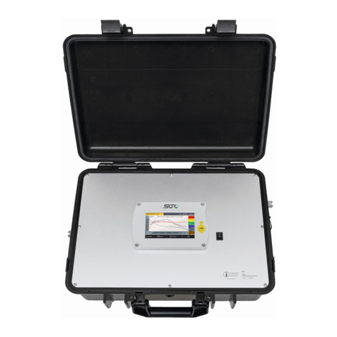
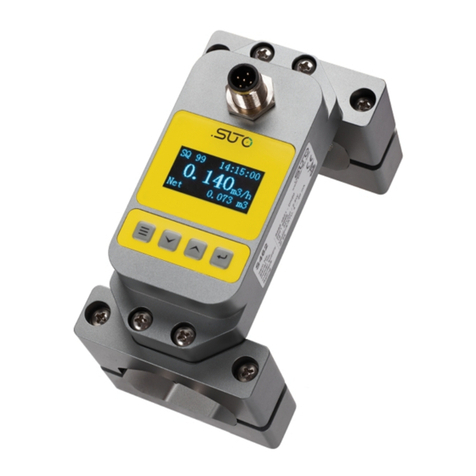
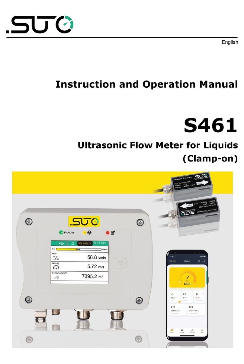
SUTO S461 Manual

English
Instruction and operation manual
S461
Ultrasonic flow meter

Dear Customer,
Thank you for choosing our product.
Before you start up the device please read this manual in full and
carefully observe instructions stated in this manual. The manufacturer
cannot be held liable for any damage that occurs as a result of non-
observance or non-compliance with this manual.
Should the device be tampered with in any manner other than a
procedure that is described and specified in the manual, the warranty is
void and the manufacturer is e empt from liability.
The device is destined e clusively for the described application.
SUTO offers no guarantee for the suitability for any other purpose.
SUTO is also not liable for consequential damage resulting from the
delivery, capability or use of this device.
2 S461

Table of Contents
1 Safety instructions......................................................................5
2 Registered trademarks.................................................................7
3 Applications................................................................................8
4 Features ...................................................................................9
5 Technical Data..........................................................................10
5.1 Measurement.....................................................................10
5.2 Signal and Interface............................................................11
5.3 General data......................................................................11
5.4 Operating conditions...........................................................12
5.5 Flow range.........................................................................13
6 Determination of installation point...............................................14
7 Installation...............................................................................16
7.1 Installing S461 main unit.....................................................18
7.2 Electrical connection............................................................19
7.2.1 M12 connection pins.......................................................19
7.2.2 Ethernet connection.......................................................21
7.2.3 M8 connection pins........................................................23
7.3 Setting S461 by S4C-US App................................................24
7.3.1 Installing S4C-US App ...................................................24
7.3.2 Scanning QR code .........................................................24
7.3.3 Basic Settings...............................................................25
7.3.4 Installation settings.......................................................27
7.4 Transducer Installation .......................................................28
7.4.1 Installing and removing the transducers...........................28
7.4.2 Removing a transducer...................................................29
7.5 Final check.........................................................................30
7.6 Other Issues and recommended actions.................................32
8 Other settings...........................................................................32
8.1 Factory settings..................................................................32
8.1.1 Fi ed delay...................................................................32
8.1.2 User calibration factor....................................................32
8.1.3 Cut-Off velocity.............................................................32
8.1.4 Bi-directional flow..........................................................33
8.1.5 Delta T Cut-Off..............................................................33
8.2 Totalizer settings.................................................................33
8.3 Alarm settings....................................................................33
8.4 Output settings...................................................................33
8.4.1 Modbus output..............................................................33
8.4.2 Analog output ..............................................................34
8.4.3 Pulse output..................................................................34
8.4.4 Alarm output.................................................................35
S461 3

8.5 Calibration.........................................................................36
8.5.1 Zero flow calibration.......................................................36
8.5.2 T-Offset calibration.........................................................36
8.5.3 User calibration.............................................................36
8.6 Logger settings...................................................................36
9 System Functions......................................................................37
9.1 Sensor info........................................................................37
9.2 Language...........................................................................37
9.3 Logger status.....................................................................37
9.4 System log.........................................................................37
9.5 Wireless sensor connection .................................................37
9.6 App version........................................................................37
10 Calibration..............................................................................38
11 Maintenance...........................................................................38
12 Disposal or waste....................................................................38
13 Appendi – Modbus register table..............................................39
4 S461

1 Safety instructions
Please check if this instruction manual matches with the
product type.
Please observe all notes and instructions indicated in this
manual. This manual contains essential information that must
be observed before and during installation, operation and
maintenance. Therefore this manual must be read carefully by the
technician as well as by the responsible user or qualified personnel.
This instruction manual must be available at the operation site of the
product at any time. In case of any obscurities or questions regarding
this manual or the product, please contact the manufacturer.
ARNING!
Voltage used for supply!
Any contact with energized parts of the product, may
lead to a electrical shock which can lead to serious
injuries or even death!
•Consider all regulations for electrical installations.
•The system must be disconnected from any power supply during
maintenance work.
•Any electrical work on the system is only allowed by authorized
qualified personal.
ATTENTION!
Permitted operating parameters!
Observe the permitted operating parameters, any
operation exceeding this parameters can lead to
malfunctions and may lead to damage on the
instrument or the system.
•Do not e ceed the permitted operating parameters.
•Make sure the product is operated in its permitted limitations.
Store and operate the product at the permitted temperature and
pressure.
•The product must be maintained and calibrated frequently, at least
annually.
S461 5

1 Safety instructions
General safety instructions
•It is not allowed to use the product in e plosive areas.
•Please observe the national regulations before/during installation
and operation.
Remarks
•It is not allowed to disassemble the product.
•Always use spanner to mount the product properly.
ATTENTION!
Measurement values can be affected by malfunction!
The product must be installed properly and
frequently maintained, otherwise it may lead to
wrong measurement values, which can lead to
wrong results.
•Do not e ceed the ma imum operation temperature of the
transducer.
Storage and transportation
•Make sure that the transportation temperature of the device is
between -30 ... +70°C.
•For transportation it is recommended to use the packaging which
comes with the device.
•Please make sure that the storage temperature of the device is
between -10 ... +50°C.
•Avoid direct UV and solar radiation during storage.
•For the storage the humidity must be <90% with no condensation.
6 S461

3 Applications
3 Applications
The SUTO ultrasonic clamp-on flow meter S461 has all it takes to
measure reliable, easy and accurate flow and consumption of liquids.
Based on the transit time technology this flow meter comes with unique
features and outstanding performance.
The sensors are simply clamped onto the outside of the pipe and never
come in contact with the fluid. The main unit can be installed onto the
pipe, at the wall or onto a DIN rail.
The configuration and setup is made through the wireless smartphone
app S4C-US, which can be downloaded for free from the SUTO website,
Google Play Store and the Apple App Store.
The app allows the user to set up the device as well as reading live
values, logger configuration and logger data read out.
By adding 2 clamp-on temperature sensors the Energy Meter Version
monitors the efficiency of heat e changers.
The S461 comes also as portable version in a transport case.
The liquids that S461 can measure include the following:
•Acetone
•Alcohol
•Benzol
•N-Butane
•Butanol
•Kerosene
•Oil, Castor
•Oil, Diesel
•Oil, Fuel
•Water, distilled
•Water, Sea
•Others (please enter sonic speed)
The S461 flow meter is mainly used in an industrial environment. It is
not developed to be used in e plosive areas.
8 S461

4 Features
4 Features
•Uses the proven clamp-on transit-time correlation technique.
•Easy to install for permanent and temporary installations.
•User friendly configuration through the dedicated smartphone App.
•A wide range of pipe sizes from DN40 to DN1200.
•Data analysis via the S4A software.
•Through additional temperature sensor inputs S461 can be used
as energy meter to monitor heat e changer.
•Bi-directional flow measurement.
•Measurement log files can be downloaded through mobile App, via
USB OTG or by using the free S4A Software.
S461 9

5 Technical Data
5 Technical Data
5.1 Measurement
Flow
Accuracy 1.0% o. RDG ±0.01 m/s
Selectable units Metric: m/s, m³/h, m³/min, l/min, m³
Imperial:ft/min, cfm, cfs, USG/min, IG/min,
bbl/min
Measuring range 0 ... 12 m/s
Repeatability 0.2% of reading
Sensor Ultrasonic sensor
Sampling rate 5 samples / sec
Turndown ratio 50:1
Response time (t90)0.1 sec
Consumption
Selectable units Metric: m³, l
Imperial: cf, IG, UG, bbl
Temperature
Accuracy 0.5 °K
Selectable units Metric: °C, Imperial: °F
Measuring range -40 ... +130 °C
Sensor Pt1000
Energy Flow
Selectable units Metric: GJ/h, kJ/h, kcal/h
Imperial: MBtu/h, Btu/h
Energy
Selectable units Metric: GJ, kJ, kcal, kWh, MWh
Imperial: MBtu, Btu
10 S461

5 Technical Data
5.2 Signal and Interface
Analog output (Optional)
Signal 4 ... 20 mA (4-wire), isolated
Scaling 0 ... ma flow, freely adjustable
Load ma . 250 Ohm
Update rate 300 msec
Pulse output (Optional)
Signal Switch output, normally open, ma . 30 VDC,
20 mA
Scaling 1 pulse per consumption unit (selectable)
Fieldbus
Protocol Modbus/RTU (Standard)
Modbus/TCP and PoE (Optional)
Supply
Voltage supply 20 ... 28 VDC
Current consumption 150 mA @ 24 VDC
5.3 General data
Configuration
Wireless S4C-US App for mobile phones
Display
Size/resolution 2.4” color (640 480) graphic display, 1
touch button
Data Logger
Storage 8 Mio. values
Material
Main Casing PC + ABS
Sensor UT-S: Industrial synthetic plastics
UTH-S: Aluminum
Miscellaneous
Electrical connection 2 M12 (4-pole): transducer
1 M12 (5-pole): Signals/Supply
1 M12: 5-pole for Analog/Pulse (standard),
S461 11

5 Technical Data
or 8-pole -coded for Modbus/TCP
2 M8 (4-pole): Pt1000 (Energy Meter
Version)
Protection class Main casing: IP65. Sensors: IP68
Approvals CE, RoHS, FCC
Weight 1.2 kg
Dimensions Main unit: 124 102 70 mm
UT-S sensor: 64 30 27 mm
UTH-S sensor: 68 34 34 mm
5.4 Operating conditions
Fluids All acoustically conductive liquids with less
than 10 % gaseous
Medium temperature -40 ... +130 °C
Ambient temperature Main unit: 0... +50 °C
UT-S sensor: 0... +80 °C
UTH-S sensor: -40... +130 °C
Ambient humidity < 99 % rH
Storage temperature -30 ... +70 °C
Transport temperature -30 ... +70 °C
Pipe sizes DN40 ... DN1200
12 S461

5 Technical Data
5.5 Flow range
DN DO Max flow
mm mm l/min m3/h cfm
40 48 905 54 32
50 60 1,414 85 50
65 76 2,389 143 84
80 88 3,619 217 128
100 114 5,655 339 200
125 139 8,835 530 312
150 165 12,723 763 449
200 219 22,618 1,357 799
250 273 35,341 2,121 1,248
300 323 50,891 3,054 1,797
500 508 141,365 8,482 4,992
1,000 1,016 565,458 33,929 19,970
1,200 1,219 814,260 48,858 28,756
Remarks:
DN: nominal inner diameter
DO: outer diameter (depends on standard and material)
S461 13

Determination of installation point
6 Determination of installation point
To maintain the accuracy stated in the technical data, the ultrasonic
transducers must be clamped on a straight pipe with unhindered flow
characteristics. The pipe can be in vertical or horizontal position.
Unhindered flow characteristics are achieved if the section in front of the
transducer (upstream) and behind the transducer (downstream) are
sufficiently long, absolutely straight and free of obstructions such as
edges, seams, curves, and so on.
The following table shows e amples of optimum installation locations.
Piping configuration
and transducer position
Upstream
dimension
Downstream
dimension
Lup
diameter
Ldn
diameter
14 S461

Determination of installation point
Principles to select an optimum location:
•Install the transducers on a long straight pipe. The longer the
better and make sure that the pipe is completely full of liquid.
•It’s recommended to place the transducers not on top of the pipe,
but rather at a side position to avoid air bubbles that may occur on
top of the pipe can effect the measurement.
•Make sure that the temperature on the location does not e ceed
the permitted temperature range for the transducers. Generally,
the closer to the room temperature the better.
•Take the pipe fouling into consideration. Select a straight and
relatively new pipe. If the condition is not satisfying, consider the
fouling thickness as part of the liner for a more accurate result.
Remarks:
Some pipes have a kind of plastic liner. Between the outer pipe and the
liner there may be a certain thickness difference that will prevent the
ultrasonic waves from direct traveling. Such conditions will make the
measurement impossible. Try to avoid this kind of pipes whenever
possible.
ATTENTION!
rong measurement may occur if the transducers
are not installed correctly.
•The flow meter is for indoor use only! At an outdoor installation,
the device must be protected from solar radiation and rain.
•It is strongly recommended not to install S461 permanently in wet
environment.
S461 15

7 Installation
7 Installation
Make sure that all components listed below are included in your
package.
Qty Description Order No.
1 S461 Ultrasonic flow meter for liquids
main unit
or
S461 Ultrasonic flow & energy meter
for liquids main unit
D695 4610
D695 4611
1 UT-S, Ultrasonic transducer pair
or
UTH-S, Ultrasonic transducer pair
S695 4610
S695 4611
2 5 m connection cable to transducers A553 0104
1 Metal stretchers Depending on pipe
diameter different P/N
1 Coupling agent A695 4610
1 Instruction manual N/A
1 S4C-US mobile App To be downloaded from
SUTO website
There are various options also available to choose from the following
order table.
Order table of the main unit mounting plate and output options
Order No. Code Description
Main unit mounting plate
A4603 A Pipe/Wall mounting plate (for pipe mounting please
order metal stretcher separately)
A4604 B 35 mm DIN hat rail mounting plate
Output options
A No further output
A4606 B 4 ... 20 mA, Pulse / Alarm
A4607 C Modbus/TCP
16 S461

7 Installation
Order table of the temperature sensors
Order No. Description
S693 4610 Temperature sensor pair, 5 m cable, M8 connector,
-40 ... +130 °C, IP42
A4615 Sensor cable length e tension (please inquire)
Order table of accessories
Order No. Description
A695 4601
A695 4602
A695 4603
A695 4604
A695 4605
Metal stretcher for sensor installation on pipes
DN40 ... DN65 (2 pieces)
DN80 ... DN100 (2 pieces)
DN125 ... DN150 (2 pieces)
DN200 ... DN300 (2 pieces)
DN350 ... DN500 (2 pieces)
A695 4608 Belt stretcher for temporary sensor installations (portable
unit), DN40 ... DN500 (2 pieces)
A695 4610 Coupling agent for sensor installation, 65 g
A554 4625 Transport casing S461 dimensions: 560 450 160 mm
A554 0107 Plug-in power supply, 100 ... 240 VAC / 24 VDC, 0.5 A ,
1.5 m cable M12 connector. Recommended for portable
unit.
A553 0154 Cable to connect power bank, 1.8 m, USB-C connector for
power bank, M12 connector
A553 0104 Sensor cable, 5 m, with M12 connector, open wires,
AWG24 (0.2 mm²)
A553 0105 Sensor cable, 10 m, with M12 connector, open wires,
AWG24 (0.2 mm²)
S461 17

7 Installation
7.1 Installing S461 main unit
1. Install the S461 main unit at the designated location. Through
optional accessories it can be mounted on the wall, on the pipe or
on a DIN hat rail.
Mounted on the wall
Mounted on the pipe
Mounted on a DIN
hat rail
2. Connect the transducers, the power supply and temperature
sensors to the designated connectors, as described in the table
below.
18 S461

7 Installation
Connector arrangement
Note: When the S461 is used as a
flow meter, there are no T in and
T out connectors.
T in: Connect to the inlet temperature
sensor.
T out: Connect to the outlet
temperature sensor.
Down: Connect to the downstream
transducer.
Up: Connect to the upstream
transducer.
Vb/Modbus: Connect to the Modbus/
RTU output/power supply.
Option: Connect to the Modbus/TCP
output when it is a X-coded connector;
connect to analog/pulse output when
it is a A-coded connector.
3. The S461 comes with an optional Earth connection, which is
recommended to be used if the unit is operated in an environment
with high electrical interference. The terminal in the connector
arrangement diagram is used for Earth connection.
7.2 Electrical connection
The S461 comes with four M12 connectors, two M8 connectors (for Flow
and Energy meter).
7.2.1 M12 connection pins
The following table lists the types of the M12 connectors based on the
outputs.
P/N Output option Connector type
A4606 4 ... 20 mA + Pulse Option (Analog)= M12 (5-pole)
Modbus/RTU Vb/Modbus = M12 (5-pole)
A4607 Modbus/TCP Option (TCP) = M12 (8-pole X-code)
S693 4610 NA Down = M12 (4-pole)
Up = M12 (4-pole)
S461 19

7 Installation
5-pole connector,
male
(View onto the sensor
connector)
Ethernet connection, male
(View onto the sensor
connector)
4-pole connector,
male
(View onto the sensor
connector)
M12 5-pole assignment
Output Type Connector Pin 1 Pin 2 Pin 3 Pin 4 Pin 5
4 ... 20 mA plus pulse
(P/N: A4606)
Option
(Analog)
NA SW SW +I -I
Modbus/RTU Vb/Modbus GND -VB +VB D+ D-
Modbus/TCP
(P/N: A4607)
Option
(Modbus/TCP)
See section 7.2.2 on the ne t page.
Color / Brown White Blue Black Grey
Legend to pin assignment (M12 5-pole)
GND: Ground for Modbus/RTU +P: Pulse output
-VB: Negative supply voltage SW: Isolated pulse output
+VB: Positive supply voltage D+: Modbus/RTU data +
+I: Positive 4 ... 20 mA signal D-: Modbus/RTU data -
-I: Negative 4 ... 20 mA signal NA: Not applicable
M12 4-pole assignment
Connector Pin 1 Pin 2 Pin 3 Pin 4
Down DN+ NC GND DN-
Up UP+ NC GND UP-
20 S461
Other manuals for S461
1
Table of contents
Other SUTO Measuring Instrument manuals
Popular Measuring Instrument manuals by other brands

Omega
Omega DP25B-E user guide

BEKA
BEKA BA488CF-P PROFIBUS PA manual

Hanna Instruments
Hanna Instruments HI-96730 instruction manual

Olympus
Olympus USPM-RUIII Series Hardware operation manual

TSI Instruments
TSI Instruments VelociCalc Plus 8384 Operation and service manual

PCB Piezotronics
PCB Piezotronics J351B31 Installation and operating manual

BUILD TEST SOLUTIONS
BUILD TEST SOLUTIONS BTS-Pulse 2.0 Instruction Manual and Safety Guidelines

Burster
Burster RESISTOMAT 2 11 Series manual

TESTO
TESTO 512 instruction manual

Teledyne
Teledyne T3SP Series Operator's manual

IFM
IFM SM4x00 operating instructions

Chauvin Arnoux
Chauvin Arnoux AEMC Instruments MR417 user manual