Peak Scientific 1B User manual

Mass Spectrometer
Table
User Manual
2014 © Peak Scientific - Rev 17 – 07/08/14
Model
Peak PN
AB Sciex PN
MS Table 1B
10-9900
5032309

MS Table User Manual
Page 2 2014 © Peak Scientific - Rev. 17 - 07/08/14
Contents
Change History 4
How to use this Manual 4
Introduction 5
Warranties and Liabilities 6
Safety Notices 7
Symbols 7
Safety Notice to Users 7
Declaration of Conformity 8
Environmental Declaration 9
Technical Specification 1B/1N/1N Hi-Flow 10
Environment 10
Inlet Conditions 10
Generator Outlets 10
Electrical Requirements 10
General 11
Technical Specification 2B/2N 11
Environment 11
Inlet Conditions 11
Generator Outlets 11
Electrical Requirements 12
General 12
Unpacking 13
Installation 14
Generator Environment 14
General Dimensions 14
Unit Controls 15
Rear Connections 16
Drain Connection – MS Table–1N/1N Hi-
Flow/2N only 16

MS Table User Manual
Page 3 2014 © Peak Scientific - Rev. 17 - 07/08/14
Water Bottle Mount Installation 17
Infinity 1031 Installation 17
Levelling Feet 18
Electrical Connection 19
Air Connection 19
Fan power LED - 2B/2N Only 20
Safe Operation of Pump Tray 21
Connecting to the Application 22
Tubing Lengths 22
IMPORTANT DOCUMENT
S
23
Normal Operation 24
Relocation of MS Table 24
Service Requirements 25
Service Schedule 25
Service Plans 25
Cleaning 25
Trouble Shooting 26

MS Table User Manual
Page 4 2014 © Peak Scientific - Rev. 17 - 07/08/14
Change History
Rev.
Comment
Name
Date
1 Initial Release Chris Pugh 18/05/07
2 Notes Added for Indoor Use Only and Altitude Tracy Grierson 10/09/07
3 Nemko Comments Added Jack Aitkinson 20/09/07
4 Final Feedback Included Gavin Logan 03/10/07
5 Added Page 22 Showing Explanation of Symbols Jack Aitkinson 23/10/07
6 Updated to New Format Liam Couttie 16/01/12
7
Power Supply Change
Liam Couttie
12/11/12
8 Change to Technical Specification Layout Liam Couttie 12/03/13
9 Technical Specifications Amended Liam Couttie 22/07/13
10 Voltage Amendment Liam Couttie 30/08/13
11 Fuse Characteristics Liam Couttie 06/09/13
12 Voltage Amendment Liam Couttie 24/10/13
13 Added Hi-Flow Information Liam Couttie 25/10/13
14 Content Update Liam Couttie 29/10/13
15 Brand Colour Change and VAVE Updates Liam Couttie 13/02/14
16 Relocation Information Liam Couttie 26/02/14
17
Declaration of Conformity Update
Liam Couttie
07/08/14
How to use this Manual
This manual is intended for end users and has been written so that it can either
be read as a step by step guide to installation and usage or as a reference
document where you can skip to the relevant information.
Users of a hard copy version can refer to the contents page to find the relevant
information. Users of the soft copy version can use the hyperlinks from the
contents page as well as the hyperlinks between sections.
Please review each of the following sections carefully.
Thank you for selecting Peak Scientific to meet your Gas Generation needs, and
should you require any further assistance or support please do not hesitate to
contact Peak Scientific or Peak Partner from which you purchased your
Generator.

MS Table User Manual
Page 5 2014 © Peak Scientific - Rev. 17 - 07/08/14
Introduction
The MS Table 1B/2B and 1N/1N Hi-Flow/2N (with integrated Nitrogen
Generator) is a transportable table designed specifically to locate a Mass
Spectrometer.
On the inside of the table is a sliding tray to support and house the Mass
Spectrometer Vacuum Pumps.
Heat removal from the inside of the table is facilitated by a range of extraction
fans located at the front and rear panels of the unit,
The MS Table 1N/1N Hi-Flow/2N, specifically, also contains an integrated
Nitrogen Generator providing a source of High Purity Nitrogen with two
independent outlets of clean Zero Grade Air.
To ensure this Generator model meets our high expectations with regards to
reliability and performance, we have tested this new model extensively at our
manufacturing plant and with end users around the world to ensure reliability
and longevity of the system.

MS Table User Manual
Page 6 2014 © Peak Scientific - Rev. 17 - 07/08/14
Warranties and Liabilities
1. The Company warrants that it has title to the Goods.
2. Subject to the provisions of this clause the Company warrants that the
Goods shall comply in all material respects with any specification
referred to in the Order Confirmation (as the same may be amended)
and shall, subject thereto, be free from defects in material and
workmanship for the lesser of a period of twelve months from the date
of delivery or thirteen months from the date of dispatch from the
factory.
3. Save as provided in this clause and except where the Goods are sold to
a person dealing as a consumer (within the meaning of the Unfair
Contract Terms Act 1977) all warranties, conditions or other terms
implied by statute or common law are hereby expressly excluded save
to the extent they may not be lawfully excluded. When the Goods are
sold to a consumer within the meaning of the Unfair Contract Terms Act
1977 their statutory rights are not affected by the provisions of this
clause.
4. In the event of the Customer making a claim in respect of any defect in
terms of clause 2 hereof the Customer must.
1. Reasonably satisfy the Company that the Goods have been
properly installed, commissioned, stored, serviced and used and
without prejudice to the generality of the foregoing that any
defect is not the direct or indirect result of lack of repair and/or
servicing, incorrect repair and/or servicing, use of wrong
materials and/or incorrect spare parts
2. Allow the company to inspect the Goods and/or any installation
and any relevant packaging as and when reasonably required by
the Company.
5. Subject to the Company being notified of any defect as is referred to in
sub-clause 2 hereof within a reasonable time of it becoming apparent
and subject always to the terms of sub-clause 4 hereof, the Company
shall, in its option, replace or repair the defective Goods or refund a
proportionate part of the Price. The Company shall have no further
liability to the Customer (save as mentioned in sub-clause 6 hereof).
6. The Company shall be liable to indemnify the Customer in respect of
any claim for death or personal injury to any person in so far as such is
attributable to the negligence or breach of duty of the Company or any
failure by the Company to comply with the provisions of sub-clause 2
hereof.
7. Save as provided in sub-clause 2 hereof the Company shall not be liable
in respect of any claim by the Customer for costs, damages, loss or
expenses (whether direct, indirect, consequential or otherwise) or
indemnity in any respect howsoever arising including, but not by way of
limitation, liability arising in negligence (other than pursuant to clause 6
above) that may be suffered by the Customer or any third party.

MS Table User Manual
Page 7 2014 © Peak Scientific - Rev. 17 - 07/08/14
Safety Notices
Symbols
This manual uses the following symbols to highlight specific areas important to
the safe and proper use of the Generator
Safety Notice to Users
These instructions must be read thoroughly and understood
before installation and operation of your Peak MS Table
Generator. Use of the Generator in a manner not specified by
Peak Scientific MAY impair the SAFETY provided by the
equipment.
When handling, operating or carrying out any maintenance,
personnel must employ safe engineering practices and
observe all relevant local health and safety requirements and
regulations. The attention of UK users is drawn to the Health
and Safety at Work Act 1974, and the Institute of Electrical
Engineers regulations.
A WARNING notice denotes a hazard. It calls attention to an operating procedure,
process or similar, which if not correctly performed or adhered to, could cause personal
injury or in the worst case death. Do not proceed beyond a WARNING notice until the
indicated conditions are fully understood or met.
A CAUTION notice denotes a hazard. It calls attention to an operating procedure,
process or similar, which if not correctly performed or adhered to, could cause damage
to the Generator or the Application. Do not proceed beyond a CAUTION notice until the
indicated conditions are fully understood or met.
Caution, risk of electric shock. Ensure power to the Generator has been removed before
proceeding.

MS Table User Manual
Page 8 2014 © Peak Scientific - Rev. 17 - 07/08/14
Declaration of Conformity
We
Peak Scientific Instruments Ltd.
of
Fountain Crescent, Inchinnan. Renfrewshire PA4 9RE
declare that:
Equipment
Nitrogen Gas Generator
Model
MS Table
To which this declaration relates, is in conformity with the applicable EC
Directives, harmonized standards, and other normative requirements.
•
Low Voltage Directive 2006/95/EC
EN 61010-1: 2010
Safety Requirements for Electrical Equipment for Measurement, Control
and Laboratory Use.
CAN/CSA-C22.2 No.61010-1-04
Safety requirements for Electrical Equipment for Measurement, Control
and Laboratory use, Part 1: General requirement.
•
Electromagnetic Compatibility Directive 2004/108/EC
EN 61326-1: 2006
Electrical Equipment for Measurement, Control and Laboratory Use –
EMC Requirements.
•
FCC 47 CFR Part 15 class B
Unintentional radiators; Conducted and Radiated emissions limits.
All evaluation, testing and certification issued by:
Nemko Canada Inc. TUV Product Service Ltd.
303 River Road Octagon House, Concorde Way
Ottawa Segenworth North, Fareham
Ontario Hampshire
Canada England
K1V 1H2
PO15 5RL
Signed By:
Name: Chris Pugh
Position: Engineering Director
Done at: Peak Scientific Instruments Ltd, Inchinnan, Scotland.
Date: 20th of July 2014

MS Table User Manual
Page 9 2014 © Peak Scientific - Rev. 17 - 07/08/14
Environmental Declaration
We
Peak Scientific Instruments Ltd.
of
Fountain Crescent, Inchinnan. Renfrewshire PA4 9RE
declare that:
Equipment
Nitrogen Gas Generator
Model
MS Table
Is fully compliant with the following Directives:
2002/96/EC WEEE (Waste of Electrical and Electronic Equipment)
2002/95/EC RoHS (Restriction of Hazardous Substances)
Peak Scientific Instruments Ltd fully complies with its obligations towards the
European WEEE (Waste of Electrical and Electronic Equipment) Directive
2002/96/EC. These obligations are being met within the B2B compliance
group.
Peak Scientific Instruments Ltd has developed all reasonable ‘due diligence’
controls to ensure that our products comply with the principles and
requirements of the European RoHS (Restriction of Hazardous Substances)
Directive 2002/95/EC. Similar directives in the United States and China, for
example, have also been captured within this program.
Where a specific certificate of compliance is required, this can be requested, on
a product serial number basis, directly from Peak Scientific Instruments Ltd, by
contacting us through our website on www.peakscientific.com
Signed By:
Name: Chris Pugh
Position: Engineering Director
Done at: Peak Scientific Instruments Ltd, Inchinnan, Scotland.
Date: 16th January 2012

MS Table User Manual
Page 10 2014 © Peak Scientific - Rev. 17 - 07/08/14
Technical Specification 1B/1N/1N Hi-Flow
Environment
Min/Max Operating Ambient Temperature
5°C (41°F) / 30°C (86°F)
Maximum Relative Humidity 70% Non-Condensing
Maximum Altitude
2000 meters
Min/Max Storage Temperature*
-20°C (-4°F) / 60°C (140°F)
*NOTE – When taken out of storage the Generator should be allowed to
acclimatize at room temperature for a minimum of 3 hours before operation.
Inlet Conditions
1B
1N
1N Hi-Flow
Min/Max Air Inlet Pressure
N/A
8.3-10 bar / 120-145 psi
Minimum Air inlet Flow
N/A 115 l/min
Generator Outlets
1B
1N
1N Hi-Flow
Curtain Max Flow
N/A
12 L/min (0.42 cfm)
10 L/min (0.35 cfm)
Curtain Max Pressure
N/A
5.50 bar (80 psi)
5.5 bar (80 psi)
Source Max Flow
N/A
26 L/min (0.91 cfm)
22 L/min (0.77 cfm)
Source Max Pressure N/A 7.50 bar (110 psi)
7.5 bar (110 psi)
Exhaust Max Flow
N/A
8 L/min (0.28 cfm)
10 L/min (0.35 cfm)
Exhaust Max Pressure
N/A
4.1 bar (60 psi)
4.1 bar (60 psi)
Dew Point N/A -11°C / 12°F
Purity
N/A
≥95
Particles
N/A
<0.01µm
Phthalates
N/A
NONE
Suspended Liquids
N/A
NONE
Gas Outlets
N/A
3 x ¼” BSPP
Drain Outlet
N/A
1 x ¼” BSPP
Pressure Gauges N/A 3
Start-Up Time For Purity
N/A
30 minutes
Electrical Requirements
Voltage
110-240 VAC
Frequency 50/60 Hz
Current
1 Amp
Input Connection
C14
Fuse T1.6A
Power Cord Type
C13
Pollution Degree
2
Installation Category II

MS Table User Manual
Page 11 2014 © Peak Scientific - Rev. 17 - 07/08/14
General
Dimensions in cm (“) W x D x H 100 x 83 x 80.4 (39.4 x 32.6 x 31.6)
Weight 1B 100 kg 1N 103.5 kg 1N Hi-Flow
103.5
kg
Shipping weight
1B
132.5 kg
1N
135 kg
1N Hi-Flow
135 kg
Noise level 54 dBA @1m
Heat Output
820 BTU / Hr
Technical Specification 2B/2N
Environment
Min/Max Operating Ambient Temperature
5°C (41°F) / 30°C (86°F)
Maximum Relative Humidity
70% Non-Condensing
Maximum Altitude
2000 meters
Min/Max Storage Temperature*
-20°C (-4°F) / 60°C (140°F)
*NOTE – When taken out of storage the Generator should be allowed to
acclimatize at room temperature for a minimum of 3 hours before operation.
Inlet Conditions
2B
2N
Min/Max Air Inlet Pressure
N/A 8.3-10 bar / 120-145 psi
Minimum Air inlet Flow
N/A 115 l/min
Generator Outlets
2B
2N
Curtain Max Flow N/A 18 L/min (0.63 cfm)
Curtain Max Pressure
N/A
5.50 bar (80 psi)
Source Max Flow
N/A
26 L/min (0.91 cfm)
Source Max Pressure
N/A
7.50 bar (110 psi)
Exhaust Max Flow N/A 25 L/min (0.88 cfm)
Exhaust Max Pressure
N/A
4.86 bar (70 psi)
Dew Point
N/A
-11°C / 12°F
Purity N/A ≥95
Particles
N/A
<0.01µm
Phthalates
N/A
NONE
Suspended liquids N/A NONE
Gas outlets
N/A
3 x ¼” BSPP
Drain outlet
N/A
1 x ¼” BSPP
Pressure gauges
N/A
3
Start-Up Time For Purity N/A 30 minutes

MS Table User Manual
Page 12 2014 © Peak Scientific - Rev. 17 - 07/08/14
Electrical Requirements
Voltage 110-240 VAC
Frequency
50/60 Hz
Current
1 Amp
Input Connection
C14 Plug
Fuse
T1.6A
Power Cord Type
C13 socket to local connection (13A minimum)
Pollution Degree
2
Installation Category II
General
Dimensions in cm (inches) W x D x H
100 x 83 x 80.4 (39.4 x 32.6 x 31.6)
Weight
2B
105 kg
2N
108.5 kg
Shipping Weight
2B
137.5 kg
2N
140 kg
Noise Level
54 dBA @1m
Heat Output
820 BTU / Hr

MS Table User Manual
Page 13 2014 © Peak Scientific - Rev. 17 - 07/08/14
Unpacking
Although Peak Scientific takes every precaution with safe transit and
packaging, it is advisable to fully inspect the unit for any sign of transit
damage.
Check ‘SHOCKWATCH’ label for signs of rough handling prior to un-packing –
Any damage should be reported immediately to the carrier and Peak
Scientific or the Peak Partner from where the unit was purchased.
Follow the unpacking instructions posted on the side of the crate. It will require
two people to remove the unit from the shipping crate and to manoeuvre the
Generator onto the floor.
Please save the product packaging for storage or future shipment of the
Generator.
Note: Included with the Generator is a “Fittings Kit” containing mains power
leads for UK, EU and US also all the required fittings. Be careful not to discard
these with the packaging.
MS Table User Manual
Page 14 2014 © Peak Scientific - Rev. 17 - 07/08/14
Installation
Generator Environment
The Generator is designed for indoor use only. It should be
installed adjacent to the application it is supplying. If this is
not convenient then the unit can be sited elsewhere, however,
consideration should be made of the lengths of pipe runs as
pressure drops can result from extended runs of pipe. Please
see the Tubing lengths section for further details.
Performance of the Generator (like all sophisticated
equipment) is affected by ambient conditions. Note should
also be taken to the proximity of Air Conditioning outlets.
These can sometimes give rise to “pockets” of air with high
relative humidity. Operation of the unit within such a pocket
could adversely affect its performance. Consideration should
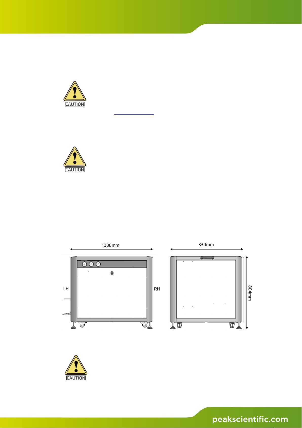
also be given to the air flow around the unit. It is
recommended that an air gap of 75mm (3”) should be
maintained down both sides, at the rear and across the top of
the unit. Please refer to the drawing below for the general
dimensions of the unit.
Maximum Ambient Conditions: 30°C (dry bulb) 70%RH (Max) Non-Condensing
General Dimensions
Figure 1: General dimensions
The Generator must always be placed on a level surface.
Failure to do so will affect the performance of the Generator.

MS Table User Manual
Page 15 2014 © Peak Scientific - Rev. 17 - 07/08/14
Unit Controls
Figure 2: Unit controls
Left Hand Side
Right Hand Side
Fan Power
LED
Exhaust Pressure
Gauge
Source Pressure
Gauge
Curtain Pressure
Gauge

MS Table User Manual
Page 16 2014 © Peak Scientific - Rev. 17 - 07/08/14
Rear Connections
Supplied in the Fittings Kit are all the fittings required to connect the MS Table
Generator to the application. The contents of the Fittings Kit are as follows:
1. 8mm Hex Key × 1
2. Washer M5 Plain × 6
3. Washer M5 Spring × 6
4. Screw M5x16 Pozi Pan Head-BZP x 6
5. C13 Mains Cable (UK) × 1
6. C13 Mains Cable (Euro) × 1
7. C13 Mains Cable (US 220V) × 1
8. C13 Mains Cable (US 110V) x 1
9. Tubing ¼” Teflon 12m Coil
*
× 1
10. Tubing 6mm High Temp. 2m Coil
*
x 1
11. ¼” Swagelok Straight Comp.
*
x 3
12. ¼” Swagelok Straight Push Fit
*
x 1
13. 6mm Blanking Plug x 1
14. User Manual – MS Table × 1
*
MS Table-1N/1N Hi-Flow/2N Only.
Drain Connection – MS Table–1N/1N Hi-Flow/2N only
Use the ¼” tubing (item 9 from fittings kit) to connect the drain outlet to a
suitable drain connection. It should be noted that the Generator can expel a
considerable amount of water from this (dependant on ambient humidity).
If a container is used it should be emptied at regular intervals.
The container must NOT have an air tight seal as water and
air are expelled at pressure.
Figure 3: Rear connections
Power connection
230VAC 50/60Hz
C14 socket
Power cord
04-1038 (EU)
04-1029 (US 220)
04-1028 (UK)
04-1039 (US 110)
Curtain, Source and
Exhaust Outputs
Air Input
Drain

MS Table User Manual
Page 17 2014 © Peak Scientific - Rev. 17 - 07/08/14
Water Bottle Mount Installation
The MS Table is supplied with a water bottle mount, which can be attached to
the left hand side of the unit.
Locate the two mounting holes, as shown in the left image below.
Then, as shown in the right image above, attach the mount to the side of the
unit using two of the M5 plain, and spring washers and M5 pozi pan head
screws contained in the fittings kit.
Infinity 1031 Installation
The MS Table-1N/1N Hi Flow/2N specifically contains an integrated Nitrogen
Generator providing a source of High Purity Nitrogen with 2 independent
additional outlets of clean dry Zero Grade air.
The MS Table-1B/2B does not have an integrated Nitrogen Generator, but does
have the facility to bolt-on to the side of the table a Peak Scientific Instruments
Wall Mounted Infinity 1031 Nitrogen Generator.
Using the remaining M5 fittings from the fittings kit, mount the Infinity 1031 to
the side of the MS Table-2B. Note the front panel of the Infinity 1031 will need
to be removed in order to attach the fittings.
Figure 4: Bottle Mount
Figure 5: Infinity 1031 Mount

MS Table User Manual
Page 18 2014 © Peak Scientific - Rev. 17 - 07/08/14
Levelling Feet
Once the MS Table has been located in its final position, the levelling feet
located at each corner of the unit can be lowered to aid stabilisation.
The TABLE is transported with the feet in a retracted position.
1. Using a 17mm spanner, slacken off
the top nut.
2. Then using a 14mm spanner
unscrew the foot until it
reaches the floor.
3. Unscrew a further 1 full turn before
tightening the locking nut to lock the
foot in place.
4. Repeat this on all four feet, ensuring the unit is level and stable when
finished.
The castors are designed to support the weight of the generator and the
mass spectrometer.
The support feet must be used in conjunction to ensure the MS Table
doesn’t move in operation.
The castors have been tested and proven to support a maximum weight of
250KG
Figure 6: Loosening Top Nut
Figure 7: Unscrew Foot
Figure 8: Lock Foot In Place

MS Table User Manual
Page 19 2014 © Peak Scientific - Rev. 17 - 07/08/14
Electrical Connection
Connect the Generator to a 110-240 VAC volt single-phase supply using the
power cord provided. If the appropriate power cord is not supplied; a new plug,
rated to at least 13 amps, can be fitted by a qualified electrician.
This unit is classified as SAFETY CLASS 1. THIS UNIT MUST
BE EARTHED. Before connecting the unit to the mains supply,
please check the information on the serial plate. The mains
supply must be of the stated AC voltage and frequency.
EARTH/GROUND (E):- Green & Yellow or Green
LIVE (L):- Brown or Black
Neutral (N):- Blue or White
Do not touch anything inside the Generator whilst the side
panels are removed and the mains power is connected to the
unit
Air Connection
The Table–1N/1N Hi Flow/2N Generator should be connected to a clean, dry,
OIL – FREE source of compressed air. A minimum inlet pressure of 120 psig (8.3
barg) is required. Any doubts as to the suitability of your compressed air
supply should be referred to Peak Scientific or any of their authorised partners.
The Compressed Air supply should be connected to the inlet located at the rear
of the unit as shown in the Rear Connections section of this manual.

MS Table User Manual
Page 20 2014 © Peak Scientific - Rev. 17 - 07/08/14
Fan power LED - 2B/2N Only
The LED on the front panel should be illuminated when the Generator is
supplied with power.
This is indication that the fans attached to the front panel are being supplied
with power, and are running correctly.
The front panel should be connected to the power supply as shown below.
Figure 9: Fan Power LED
Figure 10: Fan Power Connection
This manual suits for next models
1
Table of contents


