AMI-103
4 PEAKTRONICS
POWER / SIGNAL (J2)
Power is connected to pins 1, 2, and 3 as shown in
the Block Diagram. The fuse installed on the unit is rated
for maximum output current that can be safely delivered
by the AC outputs. To prevent damage to the unit, re-
placement fuses must not exceed a rating of 6.3A. Small-
er fuse sizes can be used with smaller motors - consult the
actuator manufacturer for appropriate fuse size and type.
The control signal to open the actuator is connect-
ed to either pin 7 or pin 9 (do not connect both inputs at
the same time) using pin 5 (OPEN COMMON) as the re-
turn. The close control signal is connected to either pin 6
or pin 8 (do not connect both at the same time) using pin
4 (CLOSE COMMON) as the return. The AC HI inputs
(pins 6 and 7) are suitable for 120VAC control signals,
while the DC/AC LO inputs are used for either DC elec-
tronic signals (such as TTL, CMOS, etc.) or AC control
signals up to 90VAC. Open collector control signals can
also be used - see Wiring Diagrams for details.
Pin 11 of J2 provides an auxiliary +24VDC output
which can be used to power an output transmitter. SIG-
NAL GND (pin 10) is used as the return line for the
transmitter. SIGNAL GND (pin 10), OPEN COMMON
(pin 5), and CLOSE COMMON (pin 4) are isolated from
the motor outputs on J1 as well as from each other. Pin 4
and 5 should not be connected to pin 10 when using con-
trol signals that are not isolated from the AC power line
(pins 1, 2, and 3).
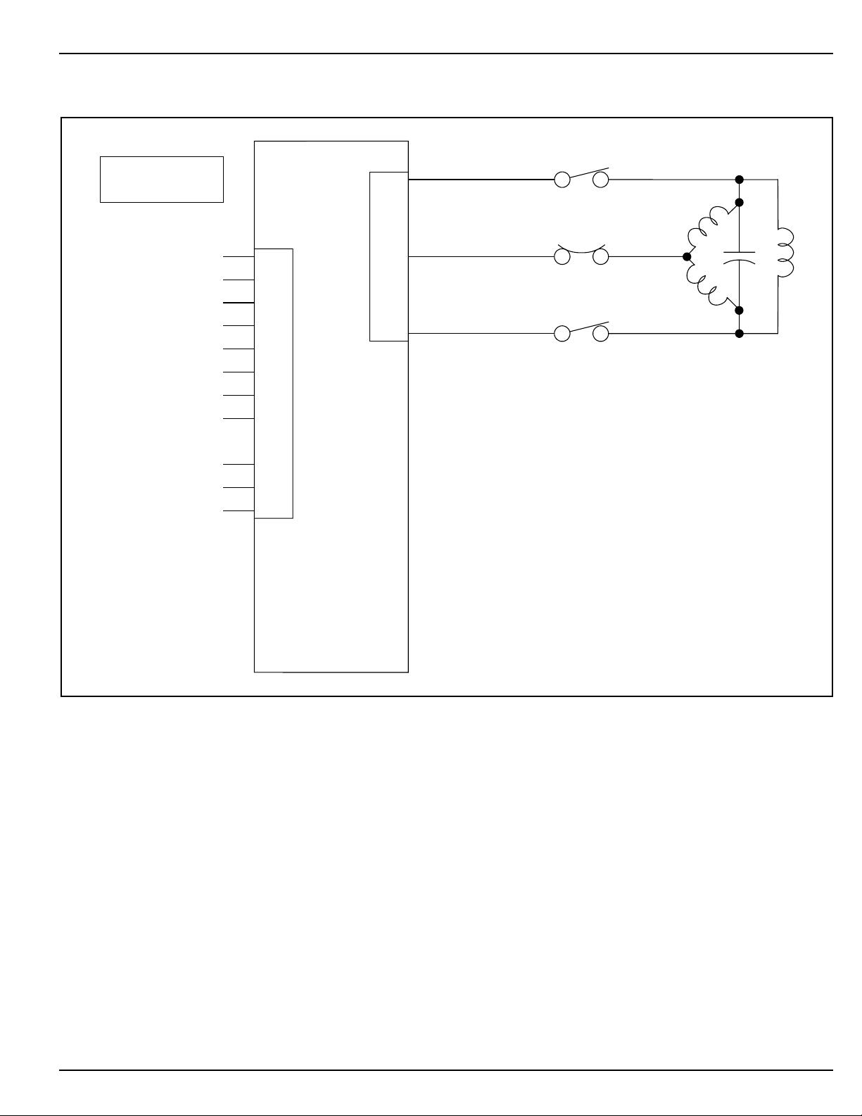
MOTOR (J1)
Pin 1 should be connected to the motor winding
that moves the actuator toward the open position, and
conversely, pin 3 is connected to the winding that moves
the actuator toward the closed position. Pin 2 is the neu-
tral or common wire to the motor windings. The AMI-
103 is suitable for powering most dynamic brakes used
with electric actuators; however, consult the actuator
manufacturer for more information.
OUTPUT INDICATORS
The AMI-103 units have on-board indicators that
identify when one of the motor outputs is turned on.
When the open output is turned on, the red LED indicator
will turn on, and when the close output is turned on the
green LED indicator will turn on (see Outline).
Many actuators are equipped with limit switches
at the open and closed positions which are intended to dis-
connect power to the motor to prevent mechanical dam-
age. For this reason, it is possible that the AMI-103 will
indicate that one of the motor outputs is turned on when
the actuator is not in motion. However, it should be noted
that when the indicator is on, power is applied to the mo-
tor output.
INPUT DELAY
Since some AC motors do not operate correctly
when power is instantaneously switched between the
Open and Close windings, the AMI-103 provides an input
delay. If one output is on and the control signal inputs are
switched to reverse the motor, the unit will delay turning
on the other output. This delay is adjustable; see Specifi-
cations under "Control Adjustments" for delay period and
Outline for location of the adjustment. When both outputs
are off and a control input signal is applied, the Input De-
lay setting causes a delay in turning on the associated out-
put. If the control signal is removed before the end of the
delay period, the associated output will not turn on.
OPEN and CLOSE SWITCHES
The AMI-103 provides on-board switches that
allow manual operation from the unit - see Outline for
location of the switches. Pressing the open switch will
turn on the Open output (J1 pin 1), while pressing the
close switch turns on the Close output (J1 pin 3). Since
the OPEN and CLOSE switches replace the control signal
inputs, the Input Delay function effects the switch opera-
tion in the same manner as a control signal - refer to IN-
PUT DELAY for more details.
To protect against turning on both outputs at the
same time, the AMI-103 will not turn on one of the out-
puts until the other output has turned off. Additionally, if
both control signals are applied at the same time, the unit
will turn off both outputs. This is true of any combination
of control signals or on-board switch operation. For ex-
ample, if a PLC is applying a control signal to the CLOSE
input while someone is pressing the open switch, both
outputs will be turned off.
2-WIRE / 3-WIRE CONTROL (JP5)
JP5 is used to configure the unit for either 2-wire
or 3-wire control - see Outline for location and setting of
JP5. In 3-wire control, the Open input signal is used to
turn on the Open output (J1 pin 1), and the Close input
signal is used to turn on the Close output (J1 pin 3).