Pearl PA-10 User manual

Caution! Read Safety and General Instructions carefully before using saw for the first ti e.
You should record the Serial Number of your Tile Saw on this
Owner’s/Operator’s Manual and on the Warranty Card. The Warranty
Card ust be sent back with all the required pertinent infor ation
for the warranty to take effect.
Covered by one or more of the following US Patents:
7302947, 7394031 and 6752139
Pearl Abrasive Co. 2.1 TILE SAW
REV. 3
™
™
MODEL PA-10™ TILE SAW
OWNER’ /OPERATOR’ MANUAL
serial number -

TABLE OF CONTENTS
I. GENERAL AFETY RULE FOR ALL POWER TOOL . . . . . . . . . . . . . . . . . . . . . . . . . . . . . . . . 3
II. YMBOL . . . . . . . . . . . . . . . . . . . . . . . . . . . . . . . . . . . . . . . . . . . . . . . . . . . . . . . . . . . . . . . . . . . 4
III. FEATURE . . . . . . . . . . . . . . . . . . . . . . . . . . . . . . . . . . . . . . . . . . . . . . . . . . . . . . . . . . . . . . . . . . . 5
IV. PECIFICATION . . . . . . . . . . . . . . . . . . . . . . . . . . . . . . . . . . . . . . . . . . . . . . . . . . . . . . . . . . . . . 5
V. UNPACKING . . . . . . . . . . . . . . . . . . . . . . . . . . . . . . . . . . . . . . . . . . . . . . . . . . . . . . . . . . . . . . . . 6
VI. IN TALLATION AND OPERATION . . . . . . . . . . . . . . . . . . . . . . . . . . . . . . . . . . . . . . . . . . . . . . 6
VII. PROPER BLADE U E . . . . . . . . . . . . . . . . . . . . . . . . . . . . . . . . . . . . . . . . . . . . . . . . . . . . . . . . . . 8
VIII. AFE OPERATING PRACTICE FOR TILE AW . . . . . . . . . . . . . . . . . . . . . . . . . . . . . . . . . . . . 9
IX. CARE AND MAINTENANCE . . . . . . . . . . . . . . . . . . . . . . . . . . . . . . . . . . . . . . . . . . . . . . . . . . 12
X. ELECTRICAL MOTOR PECIFICATION . . . . . . . . . . . . . . . . . . . . . . . . . . . . . . . . . . . . . . . . . 14
XI. REPLACEMENT PART LI T . . . . . . . . . . . . . . . . . . . . . . . . . . . . . . . . . . . . . . . . . . . . . . . . . . . 15
XII. TROUBLE HOOTING . . . . . . . . . . . . . . . . . . . . . . . . . . . . . . . . . . . . . . . . . . . . . . . . . . . . . . . . 18
XIII. ACCE ORIE AND PART . . . . . . . . . . . . . . . . . . . . . . . . . . . . . . . . . . . . . . . . . . . . . . . . . . . . 18
XIV. THE RIGHT BLADE DOE THE RIGHT JOB . . . . . . . . . . . . . . . . . . . . . . . . . . . . . . . . . . . . . 19
XV. HOW TO ORDER PART . . . . . . . . . . . . . . . . . . . . . . . . . . . . . . . . . . . . . . . . . . . . . . . . . . . . . 19
PAGE

– 3–
i. GENERAL SAFETY RULES FOR ALL POWER TOOLS
1. Know your power tool - read owner’s/operator’s manual carefully. Learn its applications and limitations as
well as the specific potential hazards unique to this tool.
2. Keep guards in place - and in working order.
3. round all tools - if tools are equipped with three prong plug, it should be plugged into a three-hole electrical
receptacle. If an adapter is used to accommodate a two-prong receptacle, the adapter lug must be attached
to a known ground. Never remove the third prong.
4. Remove wrenches - Form a habit of checking to see that adjusting wrenches are removed from tool before
turning it “on”.
5. Keep work area clean. Cluttered areas and benches invite accidents.
6. Do not use in dangerous environment. Do not use power tools in damp or wet locations, or expose them to
rain. Keep work area well lighted. Do not use tool in the presence of flammable liquids or gasses.
7. Keep children and visitors away. All children and visitors should be kept at a safe distance from work area.
8. Make workshop childproof with padlocks, master switches or by removing starter keys.
9. Do not force tool. It will do the job better and be safer at the rate for which it was designed.
10. Use right tool. Do not force tool or attachment to do a job for which it was not designed.
11. Wear proper apparel. Do not wear loose clothing, gloves, neckties, rings, bracelets or other jewelry that may
get caught in moving parts. Non-slip footwear is recommended. Wear protective hair covering to contain
long hair.
12. Always use safety glasses. Wear safety glasses (must comply with ANSI Z87.1) at all times. Everyday
eyeglasses only have impact resistant lenses; they are not safety glasses. Use face or dust mask if cutting
operation is dusty, and ear protectors (plugs or muffs) during extended periods of operation.
13. Do not overreach. Keep proper footing and balance at all times.
14. Maintain tools in top condition. Keep tools sharp and clean for best and safest performance. Follow
instructions for lubricating and changing accessories. Inspect tool cords periodically and if damaged, have
repaired by authorized service facility.
15. Disconnect tools. When not in use, before servicing, and when changing accessories, such as blades, bits,
cutters.
16. Avoid accidental starting. Make sure switch is in “off” position before plugging in power cord.
17. Use recommended accessories only. Consult the owner’s manual for recommended accessories. The use
of improper accessories may cause risk of injury to persons.
18. Never stand on tool. Serious injury could occur if the tool is tipped or if the cutting tool is accidentally
contacted.
19. Check Damaged Parts. Before further use of the tool, a guard or other part that is damaged should be
carefully checked to ensure that it will operate properly and perform it’s intended function. Check for
alignment of moving parts, binding of moving parts, breakage of parts, mounting, and any other conditions
that may affect it’s operation. A guard or part that is damaged should be properly repaired or replaced.
20. Never leave tool running unattended. Turn power “off”. Do not leave tool until it comes to a complete stop.
Read all instructions. As with all machinery there are certain hazards involved with
operation and use of the machine. The following asic safety precautions should e followed at all times to
reduce the risk of fire, electric shock and serious personal injury to you or others. Keep these important
operating instructions with this product.
WARNING!
– 4–
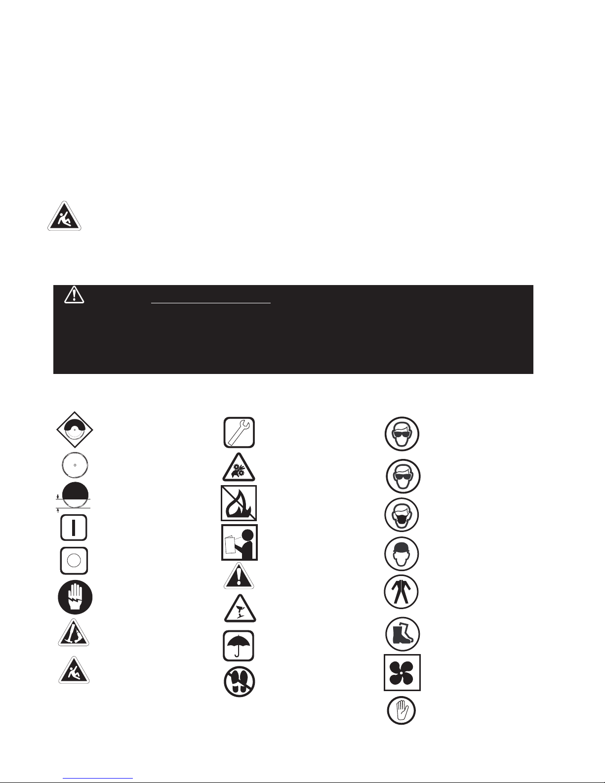
KEEP UARD IN PLACE
DIAMOND BLADE
BLADE CUTTIN DEPTH
ELECTRIC SWITCH OFF
ELECTRIC SWITCH ON
ELECTRICAL HAZARD
REMOVE TOOLS
PAY EXTREME
ATTENTION
REPAIRS TO BE DONE
MACHINE HAZARD
FLAMMABLE
READ INSTRUCTIONS
CAREFULLY
WARNIN
FRA ILE
KEEP DRY
DO NOT STEP ON
WEAR HEARIN
PROTECTION
WEAR EYE PROTECTION
WEAR BREATHIN
PROTECTION
WEAR HARD HAT
WEAR PROTECTIVE
CLOTHIN
WEAR SAFETY SHOES
WELL VENTILATED
NO NON-WORKIN
PERSONNEL
21. Extension cords. Make sure your extension cord is in good condition. When using an extension cord, be
sure to use one heavy enough to carry the current your product will draw. An undersized cord will cause a
drop in line voltage resulting in loss of power and overheating. Extension cord tables (refer to page 21) show
the correct size to use depending on cord length and nameplate ampere rating. If in doubt, use the next
heavier gage. The smaller the gage numbers the heavier the cord.
22. Do not abuse cord. Never carry tool by cord or pull it to disconnect from receptacle, Keep cord from heat,
oil, and sharp edges.
23. uard against electric shock. Prevent body contact with grounded surfaces. For example, pipes, radiators,
ranges and refrigerator enclosures.
24. Outdoor use extension cords. When tool is used outdoors, use only extension cords intended for use
outdoors and so marked.
25. Stay alert. Watch what you are doing. Use common sense. Do not operate tool when you are tired.
26. Drugs, alcohol, medication. Do not operate tool while under the influence of drugs, alcohol or any
medication.
27. Store idle tool. When not in use, tool should be stored in a dry and locked place, out of reach of children.
ii. SYMBOLS
CALIFORNIA PROPOSITION 65: Sawing and drilling generates dust. Excessive air orne
particles may cause irritation to eyes, skin and respiratory tract. To avoid reathing impairment always employ
dust controls and protection suita le to the material eing saw or drilled in accordance with OSHA (29 CFR Part
1910.1). Diamond lades improperly used are dangerous. Comply with ANSI Safety Code B7.1 and OSHA
covering speed, safety guards, flanges, mounting procedures, general operating rules, handling, storage and
general machine condition.
WARNING!
– 5––
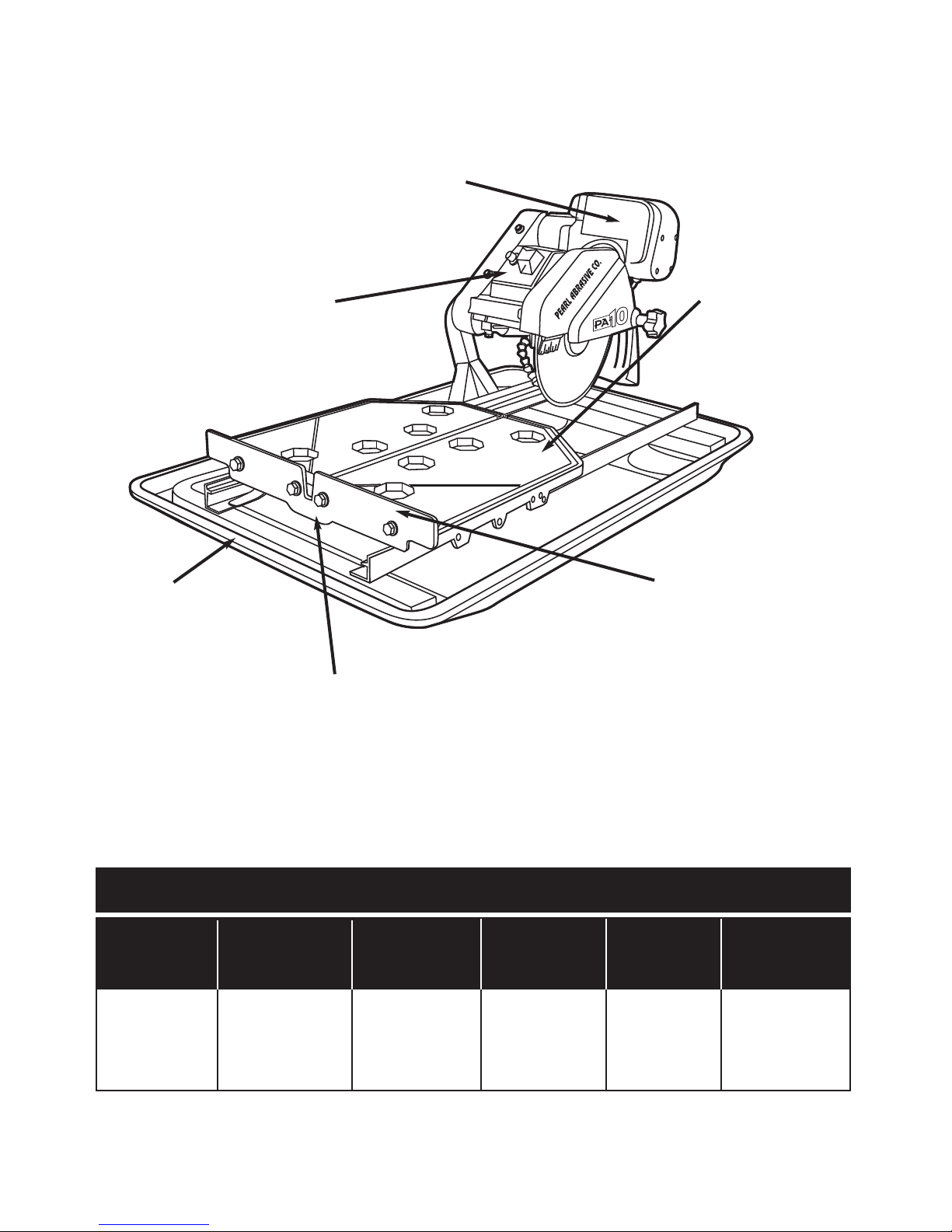
iii. FEATURES
CARBON BRUSH MOTOR
enerates more torque and is physically
smaller and lighter than similarly rated
induction motors.
STAINLESS STEEL
WATER TRAY
High durability tray
for heavy-duty jobs.
CUTTING TABLE
Features an injection mold
rubber mat that provides a
fi rm, durable work surface
while the ball bearing
wheels and rollers ensure
smooth effortless
movement.
RULER GUIDE
The guide allows convenient
measurements and promotes
precision cuts.
TABLE RETENTION DEVICE
The device secures the cutting
table when transporting the saw.
THERMAL OVERLOAD PROTECTION
Prevents the motor from overheating and
protects the saw from power surges.
PA-10 TILE SAW
MOTOR MAX. BLADE
CAPACITY
CUTTING
LENGTH
CUTTING
DEPTH WEIGHT DIMENSION
iv. SPECIFICATIONS
7" to 10"
blade with
5/8" arbor
24" rip cut,
18" diagonal cut
3-1/2" 73 lbs. 37" L
23" W
20" H
2 HP
115 v, 60 Hz,
3,000 rpm
– 6–
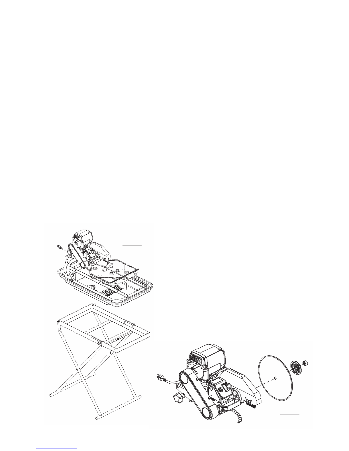
vi. INSTALLATION AND OPERATION
1. Remove the folding stand from its box.
2. While holding the stand upright, spread both
sets of legs apart and swing the workbench
over and on top of the legs.
3. Seat the saw securely onto the stand.
See Figure 1
1. Loosen blade guard adjustment knob
located at the rear of the blade guard. Raise
the blade guard to the highest position and
retighten the knob.
2. Remove the blade shaft nut and outer flange.
See Figure 2. If a blade has been mounted,
hold the blade with one hand and use the
other hand to loosen the nut with the
universal wrench. Remove existing blade.
3. Mount new blade, but make certain the arrow
on the blade coincides with the rotation
direction of the shaft.
4. Attach outer flange and blade shaft nut. Hold
the blade with one hand and use the other
hand to tighten the nut with the universal
wrench. Make certain the flanges are
pressed flush against the blade and that the
nut is firmly tightened, but do not over
tighten.
5. Loosen blade guard adjustment knob, lower
the blade guard and retighten the knob.
Figure 2
Figure 1
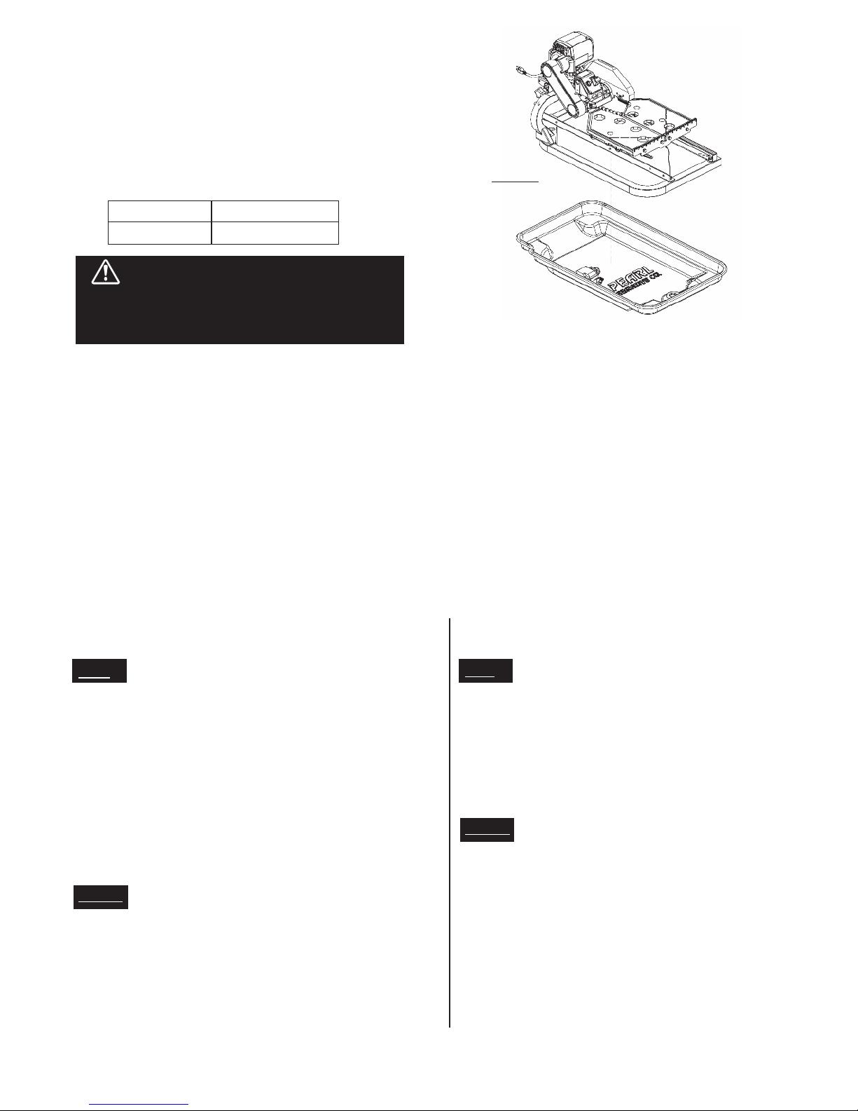
v. UNPACKING
Open the container and carefully lift the saw by the foam packaging and place it on a flat, level
working area. Be sure that you have the following items before you discard the container:
• Saw • Stainless steel water tray
• 10" saw blade • 45º/90º rip guide
• Universal wrench • Water pump
• Owner’s manual • Drain plug
SAW STAND SETUP BLADE INSTALLATION
– 7––
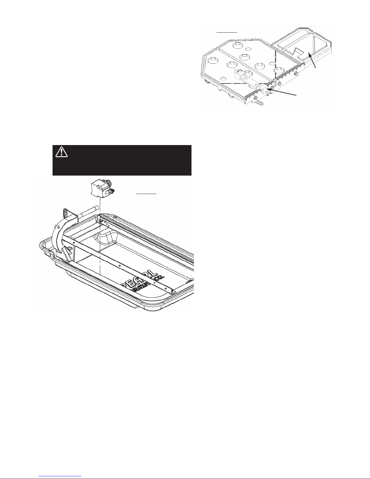
1. Remove the water pump from the box and
check that it is not damaged.
2. Slide the pump onto the U-shaped bracket
located at the bottom of the frame. The pump
should be oriented such that the water outlet is
horizontal. See Figure 3
3. Connect the water hose from the blade guard to
the pump and plug the pump’s power cord into
the female plug that is attached to the post.
4. Fill the water tray so that the water intake is fully
immersed. Proper water level must be
maintained at all times during saw operation.
WARNING: Disconnect the pump before
attempting to handle the pump. Never
operate pump without water in the tray.
1. The ruler guide has inches marked along the top
to allow convenient measurements and to
promote precision cuts. See Figure 4
2. The table the table spans an area of 16" x 16".
With the optional side extension table
equipped, the cast aluminum cutting table
spans an area of 25" x 16", which allows it to
provide greater support for handling larger
materials.
3. A rip guide should be used together with the
cutting table to ensure precision while making
cuts.
1. Set the rip guide at the desired location on the
ruler guide and tighten the threaded knob.
Make sure that the rip guide is firmly tightened
to avoid slippage. The rip guide can be used for
45˚ and 90˚ cuts.
2. After the rip guide is positioned for the desired
cut, place material flat against the rip guide and
the ruler guide.
3. Now you are ready to make your cut.
1. Remove threaded knob from the end of the rip
guide with the horizontal groove and insert it
into the other end with the diagonal groove.
2. Set the rip guide onto the ruler guide, such that
the top edge of the rip guide is aligned with the
diagonal groove to the left of the vertical
channel in the cutting table. Tighten threaded
knob once in place.
3. Place one corner of the material being cut in the
vertical slot of the ruler guide and rest the
adjoining edge flat against the rip guide.
4. Now you are ready to make your cut.
To make miter cuts, an optional miter block must
be purchased.
1. Place the lip of the miter block on the ruler
guide with the threaded knob facing you.
2. Position the miter block such that a tile laying
flat against the block may rest its left-most
edge within the vertical channel of the cutting
table. Tighten the threaded knob to secure the
miter block in place.
3. Place material onto miter block and you are
ready to cut.
Figure 3
Figure 4
WATER PUMP INSTALLATION
USING THE RIP GUIDE
PERFORMING DIAGONAL CUTS
PERFORMING MITER CUTS
USING THE CUTTING TABLE
Side
Extension
Rip Guide
– 8–
The recommended cutting depth is 1/4" below the
cutting table surface. To adjust the cutting depth,
loosen the cutting depth control knob and set the
cutting head such that the lowest point of the blade is
1/4" below the table surface.
Blade Diameter Cutting Depth
1. Lift the saw up from inside the water tray.
2. Remove the drain plug and drain any water left
inside the water tray.
3. Flush water into the tray while holding it upright to
remove any sludge buildup.set in the water tray for
better handling.
4. Replace the saw back into the water tray. Figure 5
1. Ensure that the water tray is empty and dry.
2. Unplug the power cord and store it in the water
tray.
3. Secure the cutting table to the front of the saw
using the table retention device.
4. Tighten the cutting depth control knob.
5. Optionally the rear drip tray may be removed and
set in the water tray for better handling.
D ’S
• Inspect blades daily for cracks or uneven wear.
• Always use appropriate blade for material being cut.
• Inspect arbor shaft for uneven wear before mounting blade.
• Always use blades with the correct arbor shaft size.
• Ensure that blade is mounted in the correct direction.
• Use proper safety equipment when operating the saw.
• Always have a continuous flow of water on both sides of
blade.
• Secure the blade to the arbor with a wrench.
D NT’S
• Do not operate the saw without safety guards in position.
• Do not operate the saw with blades larger than 10".
• Do not cut dry with blades marked “Use Wet”.
• Do not exceed manufacturer’s recommended maximum RPM.
• Do not force blade into material. Let blade cut at its own
speed.
D ’S
• In addition to the following, always follow wet
recommendations.
• Use appropriate blade for material being cut.
• Inspect segment blades for segment cracking or loss.
• Do not use damaged blades.
• Use proper safety equipment when operating the saw.
D NT’S
• In addition to the following, always follow wet
recommendations.
• Do not make long cuts with dry blades. Allow them
to air cool.
• Do not use the edge or side of blade to cut or grind.
• Do not attempt to cut a radius or curve.
• Do not cut too deep or too fast into the material.
• Do not cut any material not recommended by blade
manufacturer.
TRANSPORTING THE SAW
WET CUT BLADES DRY CUT BLADES
Figure 5
vii. PROPER BLADE USE
Setting the lade too low may
damage the cutting ta le and if set too high, the
lade may gra the material eing cut, possi ly
causing injury to the operator and the saw.
WARNING!
CLEANING THE WATER TRAY
SETTING THE CUTTING DEPTH
7" 1-3/4 inch
10" 3-1/4 inch

– 9––
viii. SAFE OPERATING PRACTICES FOR TILE SAW
1. Use safety equipment - wear safety approved
hearing, eye, head and respirator protection.
2. Read and understand the symbol definitions
contained in this manual.
3. Read and understand all warnings and
instructions on the machine.
4. Read all safety materials and instructions that
accompany any blade or accessory used with
this machine.
5. Establish a training program for all operations
of this machine.
6. Always provide a copy of this manual to the
equipment user. If you need extra copies
call our Customer Service Department at
1-800-969-5561.
7. Always select a diamond blade according to
the manufacturers recommendation suitable
for the material to be cut. Never use a blade
having a maximum operating speed lower than
the “No load R.P.M.” marked on the tool
nameplate. Do not operate any saw without
safety guards in place or with a blade diameter
larger than the maximum saw blade capacity.
8. Before mounting a blade on the saw clean and
inspect the arbor shaft, blade flanges and the
diamond blade for uneven wear or damage. If
it appears to be damaged, Do not operate the
tool. Have it serviced by a qualified service
technician.
9. Before each use of the saw, inspect the
diamond blade for hairline fatigue cracks. If
such a crack or flaw is evident, discard the
blade. Using a damaged lade may cause
injury to the operator or others.
10. Be sure that the blade arbor hole matches the
blade adapter flange supplied with the saw.
Use only blade adapter flanges that came on
your saw. Never use damaged or worn blade
adapter flanges.
11. Installing the blade, install the blade with the
arrow pointing the same direction as the
rotation of the arbor shaft or the arrow on the
blade guard. Be sure to tighten the blade shaft
arbor nut with the wrench provided.
Be careful not to over tighten.
12. Check that the blade tracks near the center of
the channel in the main table, and that the table
moves freely from front to back.
13. Sometimes the material being cut is not
abrasive enough to expose new diamonds on
the blade. If the blade is not sharpened, it will
rub against the surface resulting in heat build
up in the core. To prevent this, it is necessary
to dress the blade. To dress the blade simply
cut something that is very abrasive such as a
piece of cement block. Indications that the
blade needs dressing includes:
• The diamond in the matrix appear shiny
because they are worn flat.
• The blade stops cutting or noticeably
slows down.
Blade dressing stones are available from your local earl
Warehouse.
14. Before using the saw fill the water tub enough
to submerge the water pump with clean water
only. Replenish as necessary and clean the
water tub frequently. Do not operate a wet
cutting blade without adequate water flow to
both sides of the blade. Never run the pump
dry.
15. When cutting, always hold the material firmly
lying flat, supported by the main table with one
edge resting against the main table backstop.
The dust generated y cutting
of tile, mar le, stone, ricks etc. can e injurious
to your health. Always operate machinery in well
ventilated areas and provide proper dust removal.
Always wear a dust mask approved for respiratory
protection against these types of dusts and mists.
For your own safety and the
safety of others do not attempt to operate this saw
until you have read and understand the general
safety rules for all power tools and the following
additional safety precaution unique to this saw.
WARNING!
WARNING!
Not dressing the lade
frequently or setting the lade too high will cause
it to gra the tile possi ly causing injury to the
operator and the saw. Setting the lade depth too
low will cause it to cut into the main ta le that
may result in injury.
WARNING!

– 10 –
• Do not attempt to cut pieces too small to
safely hold down on the main table.
• Never use the side of the blade to cut or
grind with, only cut in a straight line.
• Keep all parts of your body away from the
blade and all other moving parts.
• Never touch or try to stop a moving blade
with your hand.
16. When cutting dry - always unplug the water
pump first. Never run the pump dry.
• Do not use a wet cutting blade for dry
cutting. Select the proper dry cutting
blade for your application.
• Never make long continuous cuts with dry
cutting blades. To avoid heat build up,
allow the blade to cool, remove the tile
and allow the blade to run freely for a few
minutes.
IMPORTANT - If there is any tendency for the
saw to tip or ove during certain operations,
such as when cutting large heavy tile; the saw
ust be securely fastened to a supporting
table.
17. Make certain all adjusting knobs or locks are
tight and engaged in their detents and that
movable parts not intended to move during
operation are securely locked before making a
cut. Be careful not to over tighten.
18. Before connecting the machine to a power
source check to see that the “On/Off” switch is
in the “off” position.
• Make sure the blade is not contacting
anything before connecting to a power
source and starting the motor.
• Know how to stop the machine quickly in
case of an emergency.
19. rounding Instructions
• In the event of a malfunction or
breakdown, grounding provides a path of
least resistance for electric current to
reduce the risk of electric shock. This tool
is equipped with an electric cord having
an equipment-grounding conductor and a
grounding plug. The plug must be
plugged into a matching outlet that is
properly installed and grounded in
accordance with all local codes and
ordinances.
• Do not modify the plug provided - if it will
not fit the outlet, have the proper outlet
installed by a qualified electrician.
• Improper connection of the equipment-
grounding conductor can result in a risk
of electric shock.
• Check with a qualified electrician or
service personnel if the grounding
instructions are not completely
understood, or if in doubt as to whether
the tool is properly grounded.
• Use only 3 wire extension cords that have
3 prong grounding plugs and 3 pole
receptacles that accept the tool’s plug.
Repair or replace damaged or worn cord immediately.
This tool is intended for use on a circuit that has an outlet
that looks like the one illustrated in Figure 6. The tool has
a grounding plug that looks like the plug illustrated in
Figure 6(A). A temporary adapter, which looks like the
adapter illustrated in Figure 6(B) and 6(C), may be used
to connect this plug to a 2 pole receptacle as shown in
Figure 6(B) if a properly grounded outlet is not available.
The temporary adapter should be used only until a
properly grounded outlet can be installed by a qualified
electrician. The green-colored rigid ear, lug, and the like,
extending from the adapter must be connected to a
permanent ground such as a properly grounded outlet
box.
Note: USE OF A TEMPORARY ADAPTER IS NOT
PERMITTED IN CANADA.
Additionally, water pump requires the use of a round
Fault Circuit Interrupter. Therefore, when using the water
pump receptacle, this tool must be plugged into a
properly installed round Fault Circuit Interrupter outlet.
See Figure 6(D). If a round Fault Circuit Interrupter
outlet is not available, Pearl Abrasive Co. has it available
as an accessory item. A plug-in round Fault Circuit
Interrupter may be plugged into a properly installed and
grounded 3-pole outlet. Refer to Figure 6(E).
20. Position of the Tile Saw
• To avoid the possibility of the appliance
plug or receptacle getting wet, position
tile saw to one side of a wall mounted
NOTE - Use of a Te porary Adapter is not per itted
in Canada.

– 11 –
receptacle to prevent water from dripping
onto the receptacle or plug. The user
should arrange a “drip loop” in the cord
connecting the saw to a receptacle. The
“drip loop” is that part of the cord below
the level of the receptacle, or the
connector if an extension cord is used, to
prevent water traveling along the cord and
coming in contact with the receptacle.
See Figure 7.
• If the plug or receptacle does get wet,
Do not unplug the cord. Disconnect the
fuse or circuit breaker that supplies power
to the tool. Then unplug and examine for
presence of water in the receptacle.
21. Extension Cords
• Use only extension cords that are
intended for outdoor use. These extension
cords are identified by a marking
“Acceptable for use with outdoor
appliances; store indoors while not in
use.” Use only extension cords having an
electrical rating not less than the rating of
the product. Refer to chart on page 14.
Do not use damaged extension cords.
Examine extension cord before using and
replace if damaged. Do not abuse
extension cords and do not pull on any
cord to disconnect. Keep cord away from
heat and sharp edges. Always
disconnect the extension cord from the
receptacle efore disconnecting the
saw from the extension cord.
* round Fault Circuit Interrupter ( FCI)
protection should be provided on the
circuit(s) or outlet(s) to be used for the
tile saw. Receptacles are available having
built-in FCI protection and may be used
for this measure of safety.
(A) (B)
Figure 6
Grounding Methods
(C) (D) (E)
rounding pin
rounding pin
Cover of
grounded
outlet box
Metal
Screw
rounding
Means
(Lug)
To reduce the risk of electrocution, keep
all connections dry and off the ground.
Do not touch plug with wet hands.
TOOL
Figure 7
Drip Loop
Supporting
Surface
Power Cord
Drip Loop

– 12 –
ix. CARE AND MAINTENANCE
For your safety efore performing any maintenance on the saw turn off the power switch
and unplug the power cord.
WARNING!
GENERAL RULES
• Always clean the machine before performing any
maintenance/ repair.
• Before performing any cleaning/maintenance
/repair, the machine must be switched off with the
main power switch.
Steps to Follow When Cleaning:
• Please do not use aggressive cleaners (i.e.
containing solvents). Do not use high-pressure
water jets, aggressive detergents or solutions and
liquids with a temperature exceeding 86ºF! Use a
fluff-free cloth only.
• Use a cloth which may be lightly moistened only for
removing dust and dirt. Hard packed dirt can be
removed with a soft brush.
• For the sake of safety, no water/cleaning
liquid/vapor may penetrate into the electric motor,
connectors/plugs, switches, etc. Therefore cover
all apertures, holes in the housing, connectors or
plugs, etc. or seal them with adhesive tape!
• Use a soft, low-pressure water jet and a brush to
rinse dirt and incrustations away. Be particularly
careful when near hazardous parts of the machine
(e.g. switch, motor). Clean the motor and switches
only by wiping with a moist cloth.
• Do not “rinse” the bearings of the drive elements to
prevent them from running dry. The ball bearings
of the machine are permanently lubricated.
• After cleaning, remove all covers and adhesive
tape! All screws/nuts which you may have
loosened must be tightened again!
• After wet cleaning, try the machine on a power
outlet which is equipped with a power breaker (i.e.
fault current circuit breaker). If the fault current
circuit breaker cuts the power supply, the machine
must be inspected by an authorized dealer prior to
use!
CLEANING
After every use of the machine:
• Remove dirty water from container.
• Remove dirt and mud from the bottom of the
container.
• Rinse the immersion pump with fresh water to
prevent the water pump from clogging with
residual dirt.
After wet cleaning and before using the machine
again:
• Connect the machine to an electric power outlet
equipped with a “ FCI” safety power breaker. If the
safety power breaker cuts off the electrical power
supply, do not try to operate the machine but have
it checked by an autho-rized dealer first.
PROLONGED PERIOD OF NON-USE
Before not using the machine for a prolonged period
of time:
• Clean and lubricate all movable parts. However, do
not grease the guide rails.
After not using the machine for a prolonged period of
time:
• Check that the stand is safely fixed.
• Check that all screw joints and nuts are fixed.
• Check that the cutting table is seated properly on
the guide rails and that it moves easily along the
entire length of the rails.
• With the saw blade removed, switch on the motor
for an instant and switch it off again. If the motor
does not run, have the machine inspected by a
qualified electrician.
• Check that the immersion pump works properly.
Turn on the cooling water tap and switch the
machine on. If the pump does not give any water or
only a little, switch the machine off at once. Clean
the pump, or replace if necessary.
EXTREME TEMPERATURE
Ambient temperature below 32° F (Winter):
• To prevent the water in the pump and cooling
system from freezing, remove the water after using
the machine or when there will be a long break.
Make sure that the cooling system is entirely
drained so that there is no water left inside the
pump and water hose!
– 13 –
WATER PUMP MAINTENANCE
When the machine has not been used for a long period of time,
hard packed dirt may begin to build up inside the pump and
block the pump wheel. If the machine is activated with the
immersion pump blocked, the electric motor of the pump will
be damaged within a few minutes! Please follow the steps
listed below to clean the pump before operating the saw:
1. Remove the immersion pump from the water container.
2. Clean the immersion pump.
3. Loosen the fixing screws of the pump lid.
4. Take the lid off the pump. Be careful not to damage or lose
the gasket underneath.
5. Clean the pump lid.
6. Remove all dirt and incrustations from the pump wheel.
7. Check whether the pump wheel can be easily turned.
8. Then reassemble the immersion pump correctly and check
whether it works properly.
BELT REPLACEMENT
1. Unplug the saw before proceeding any further.
2. Loosen and remove the four bolts located above and
below the belt guard and then remove the belt guard. See
Figure 8
3. Loosen the four bolts located at the base of the motor.
4. Use a hex wrench to access the socket hex bolt located at
the rear of the cutting head. Turn wrench to move the
motor forward, thus providing some slack in the belt.
5. Remove existing belt and replace with a new belt.
6. Perform steps 1 through 4 in reverse to tension the belt
and reinstall the belt guard. Make sure the belt is at the
proper tension before tightening the four bolts at the base
of the motor.
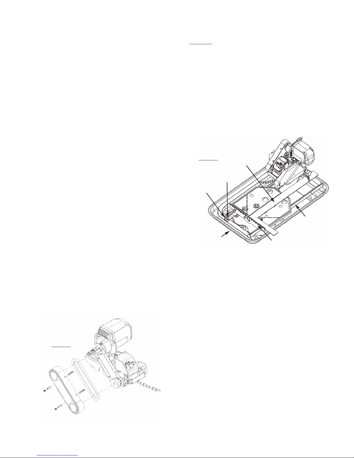
REALIGNMENT
Method 1:
This procedure deals with the most common source of
misalignment that occurs when the guide rails are not parallel
with the blade.
1. Set the cutting depth such that the blade passes through the
table, not over.
2. Place a straight edge (i.e. carpenter’s square) on the cutting
table as shown in Figure 9.
3. Loosen the left and right guide rails by loosening the
fasteners found at the ends of the rail. See Figure 9. The left
rail should be slightly loose, so there is not too much play
during adjustments, but the right rail should move freely.
4. Make sure the short portion of the straight edge is placed
flush against the ruler guide. Adjust the left guide rail so
that the front and rear edges of the blade touch the straight
edge, although a tolerance of 0.1mm between the front and
rear edges is allowed. Perform this adjust-ment along the
entire length of the straight edge.
5. Position the table as close to the user as possible. Place the
straight edge flush against the ruler guide and blade.
Without holding onto the straight edge, gently move the
table towards the rear of the saw and then back. Observe
any gaps that may appear between the straight edge and
blade or between the straight edge and ruler guide. A gap
exceeding the allowed tolerance means that the table is not
moving parallel to the blade; hence, further adjustments as
outlined in step 4 will be required. However, if scenario A
or B described below occurs, other adjustments may be
required instead.
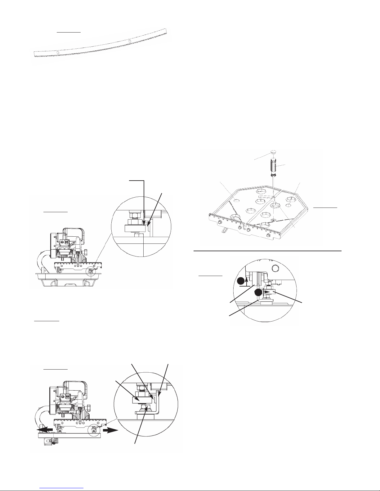
A. If the straight edge only touches the blade when the
table is positioned midway along the rail or at the
ends of the rail, then the rail may be deformed (i.e.
bowed). See Figure 10. Perform test cuts to
determine if the rail should be replaced. Typically a
bowing displacement of up to 0.2mm will not affect
cutting accuracy.
Figure 9
Fastener
Front
Straight
Edge
Ruler Guide
Left Guide Rail
Right Guide
Rail
Straight
Edge
Figure 8
– 14 –
B.If the straight edge touches both edges of the
blade intially, but shifts apart as the table travels
along the rail, proceed to method 2 below.
6. Tighten the fasteners at both ends of the left rail.
7. Adjust the right guide rail so that the horizontal rollers
underneath the table engage the rail as shown in Figure
11. In most cases the rollers will not have to be verti-
cally adjusted. Spacing between rails must be equidis-
tant at all points to ensure that they are parallel. Once
adjustments are made, lightly tighten the fasteners on the
right rail and move the table back and forth. If the table
binds against the rail at any point, adjust spacing
accordingly until the table moves smoothly.
8. Tighten the fasteners at both ends of the right rail.
If alignment has been achieved, do not proceed to method 2.
Method 2:
This procedure corrects another source of misalignment
that occurs when the table’s orientation is not parallel with
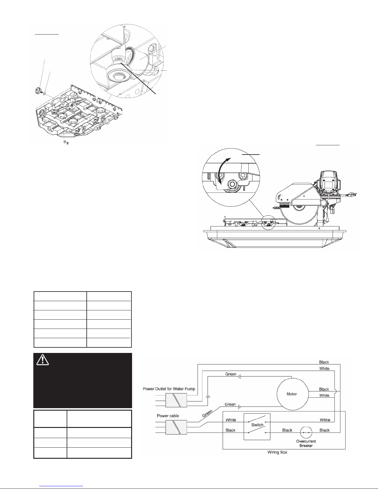
the guide rails.
1. Lift the saw up from within the water tray and place it on
a flat level surface. Use the universal wrench to loosen
(but do not remove) the fasteners from either end of both
guide rails. Move each rail away from the other, so that
the horizontal rollers are clear of the right guide rail. See
Figure 12.
2. Remove rubber cap A on the left side of the table. Loos-
en the exposed lock nut using a 13mm socket wrench.
Use a flat screwdriver to turn the shaft of the roller clock-
wise to lower it by approximately 3/8". See Figure 13.
Evenly lift up the table to disengage the guide rollers from
the left guide rail. Once the guide rollers are clear, shift
the table to the right to clear the left horizontal roller of
the rail. Remove the table from the guide rails. See
Figure 14.
3. If the table shifts to the right as it travels away from the
user, a shim needs to be added to the guide roller fur-
thest from the ruler guide. On the other hand, if the table
shifts to the left, a shim needs to be added to the guide
roller closest to the ruler guide. Remove the appropriate
guide roller to insert a shim between the roller and table,
then reattach. See Figure 15. Depending on the severity of
the shift, more than one shim may be required.
4. After adding shim(s), mount the table onto the guide rails
by reversing the instructions in step 2. Move the rails
toward each other to engage the horizontal rollers to the
right guide rail as shown in Figure 11. Realign the table
to the blade using method 1. Check to see if any shifting
persists. A shift tolerance of 0.2mm is allowed. A shift
in excess of that will require further adjustment—repeat
step 3.
Figure 10
Figure 11
Leave hairline gap
between rail and roller
Leave a 1/32"
(1mm) gap
Figure 12
Clearance
Horizonta
l Roller
Horizonta
l Roller
Right Guide
Rail
Loosen
Fasteners
Figure 13
Rubber Cap B Flat Screw Driver
Rubber Cap A Rubber Cap C
Size 13mm Socket
Wrench
Figure 14
Horizontal
Roller
1
2
Guide Roller
Left Guide
Rail
– 15 –
x. ELETRICAL MOTOR SPECIFICATIONS
Horse Power 2 hp
Volts 115 V/ 60hz
Amps 15 amps
Motor RPM 3,450 rpm
Cycle 60
Phase 1
WIRE
GAUGE
No. 12
No. 10
No. 8
LENGTH F C RD
25'
50'
75'
Recommendations:
• It is recommended that a 15 amp circuit be used while operating this saw.
This will prevent possible power interruption or loss.
• Always plug saw as close as possible to the power source while operating.
This will allow you to receive optimum electricity.
Electrical Wiring Diagram
WARNING: To avoid
permanent motor damage you
must use the correct extension
cord. Never use more than one
extension cord at a time. Follow
the chart for proper size.
5. Once alignment is successful, replace saw back into the
water tray.
LEVELING ADJUSTMENT
This procedure levels the table so that it is perpendicular to
the blade and flush against the rails.
1. Remove rubber caps B and C on the right side of the
table. Loosen the exposed lock nuts using a socket
wrench. Next, use a flat screwdriver to turn the shaft of
the rollers clockwise. See Figure 13. This will lower the
horizontal rollers to allow room for adjusting the flat
rollers.
2. Loosen the socket bolts on the flat roller plate so that the
roller can swing freely about one bolt. See Figure 16. Do
this for both flat roller plates.
3. Hold the table against the guide rails. The flat rollers
should reposition themselves to maintain contact with the
guide rails. If the table is not perpendicular to the blade,
lift the right side of the table instead to obtain the proper
angle. A square tool will be required to confirm the angle.
Tighten the socket bolts. Check the table for play. Repeat
step 2 if some play is still present.
4. Restore the horizontal rollers to their original positions as
shown in Figure 11 by reversing the instructions in step
1. Be sure to tighten the lock nuts and replace the rubber
caps.
Figure 15
Guide Roller
Shim
Flat
Roller
Horizonta
l Roller
Flat rollers rotate in this
manner
Figure 16

– 16 –
xi. TROUBLESHOOTING

– 17 –
For your safety and the safety of others, turn the power switch off and always remove the
plug from power source efore trou leshooting. Repairs performed y unauthorized
personnel could cause serious hazard. We recommend that service to this tool e performed y a qualified service
technician with original equipment replacement parts.
WARNING!
– 18 –
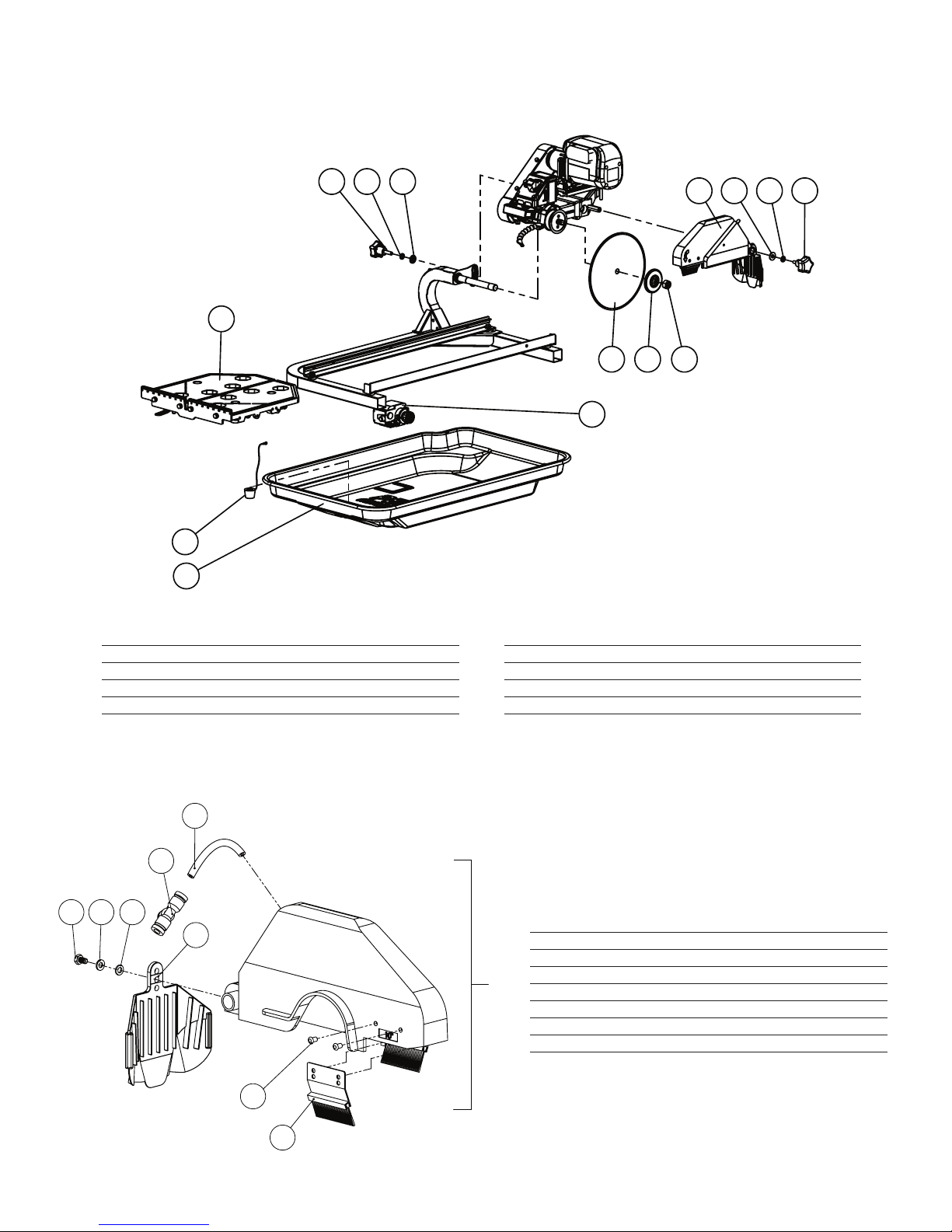
xii. REPLACEMENT PARTS LIST
PA-10 MAIN A EMBLY
1 Water plug assembly S1000-48
2 253 gal/hr Water pump CX38011
3 Cutting table assembly PA100133
4 10" blade DTL10HPXL
5 10" Outer flange PA100136
6 5╱8 - 11 UNC Nut PSV00004
7 Blade guard assembly PA100204
8 3/8 Waved lock washer (2) PA0310
9 3/8 Narrow washer inch (2) PA0309
10 Male 5/16 - 18 UNC x 3/4L Star type knob PSV10022
11 Male 3╱8 - 16 UNC x 32L Star type knob PA100021
12 VX10.2XL/PA10 Water tray V35012SSXL
PART NAME PART NUMBER PART NAME PART NUMBER
PA-10 BLADE GUARD A EMBLY
8:75469;3
1 Blade guard assembly PA100204
2 M6 Spring lock washer V3911090
3 M6 Narrow washer PA00082
4 M6 x 1.0 x 10L Hex bolt PA100062
5 Splash guard PSV10023
6 D8 Female quick disconnect T-adapter PSV00005
7 PU hose (per foot) PSV00040
8 M5 Standard rivet (4) PA100033
9 60L Water brush (2) PSV10020
PART NAME PART NUMBER
– 19 –
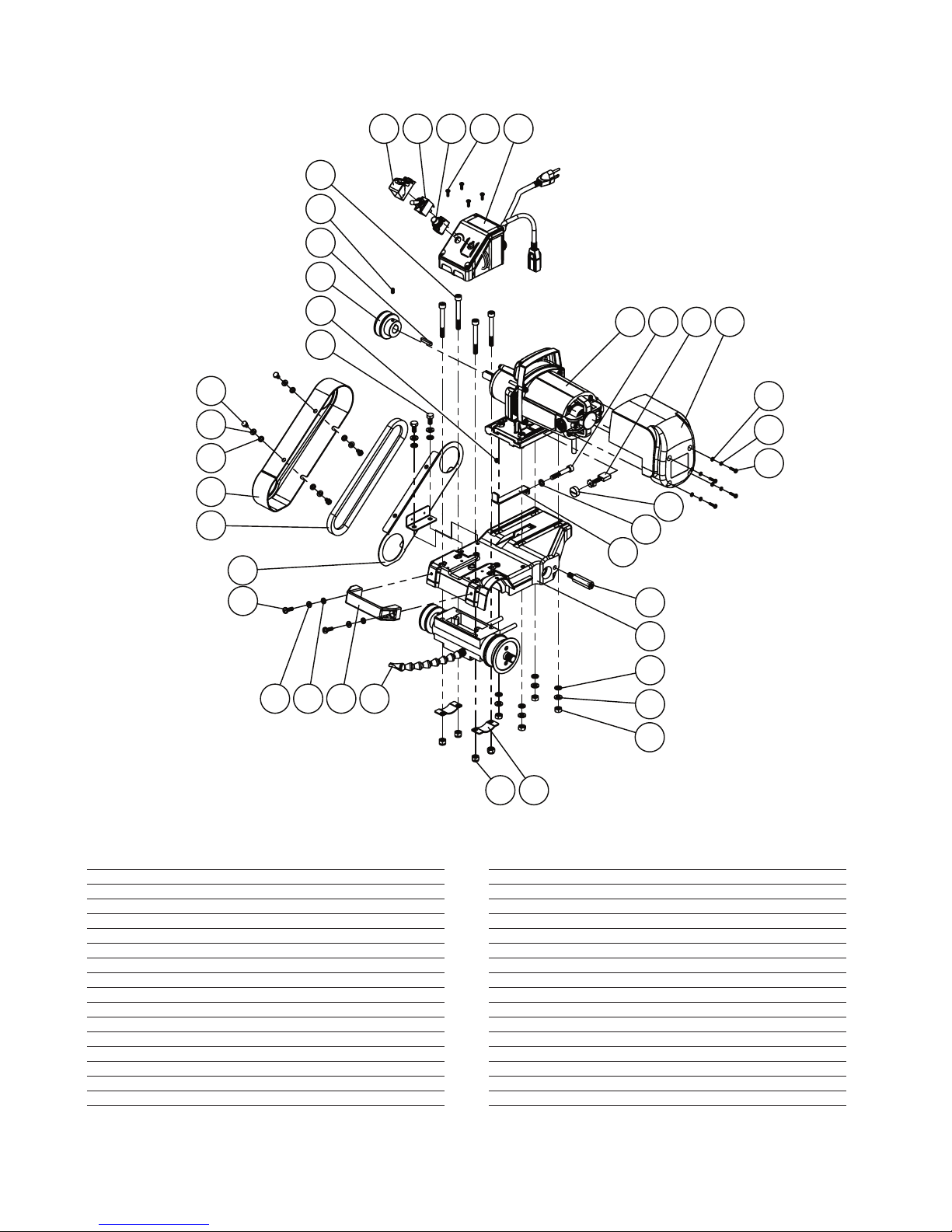
PA-10 CUTTING HEAD A EMBLY
1 Motor Mounting Plate PA100201
2 Motor tension bracket PA100074
3 2HP Brush motor complete w/ fan cover PA100066
4 Belt guard bracket PA100069
5 10" Variant LCBH ver2 (black) PA100202
6 Power switch assembly PA100076
7 LCBH bracket (black) (2) PA100203
8 26.5H X 7W X 93L Rectangle handle. PA100073
9 Belt PA100072
10 Belt guard PA100067
11 Hexagonal blade guard shaft PA100068
12 D53.98mm V-belt pulley PA100092
13 D6 Circular rubber stop PA100075
14 5 x 5 x 30L Square key PA100093
15 M6 x 1.0 x 10L Flat point set screw PA0316
16 M8 Narrow washer (7) PA0120
17 M6 Narrow washer (6) PA0384
18 M8 x 1.25 x 50L x 22S Socket head cap hex screw PA150185
19 M8 x 1.25 x 70L x 22S Socket head cap hex screw (4) PA0329
20 M8 Spring Lock Washer (6) PA0121
21 M6 Spring Lock Washer (6) PA11090
22 M8 x 1.25 Nut (4) PA0119
23 M6 x 1.0 x 20L Cross screw (2) PA110026
24 M4 x 0.7 x 12L Cross screw (4) PA141113
25 M8 x 1.25 x 16L Hex bolt (2) PA01161
26 M6 x 1.0 x 10L Hex bolt (4) PA0322
27 M8 x 1.25 Nylon Nut (4) PA0155
28 Fan cover PA100150
29 Carbon brush (2) V390051
30 Carbon brush cap (2) V390050
31 M4 Narrow washer (4) PA420044
32 M4 Spring washer (4) PA15999
33 M4 x 0.7 x 16L Cross screw (4) PA03051
34 Power switch shield PA100003
35 20A Toggle switch PA141027
36 20A Circuit breaker PAS1000-04
PART NAME PART NUMBER PART NAME PART NUMBER
– 20 –
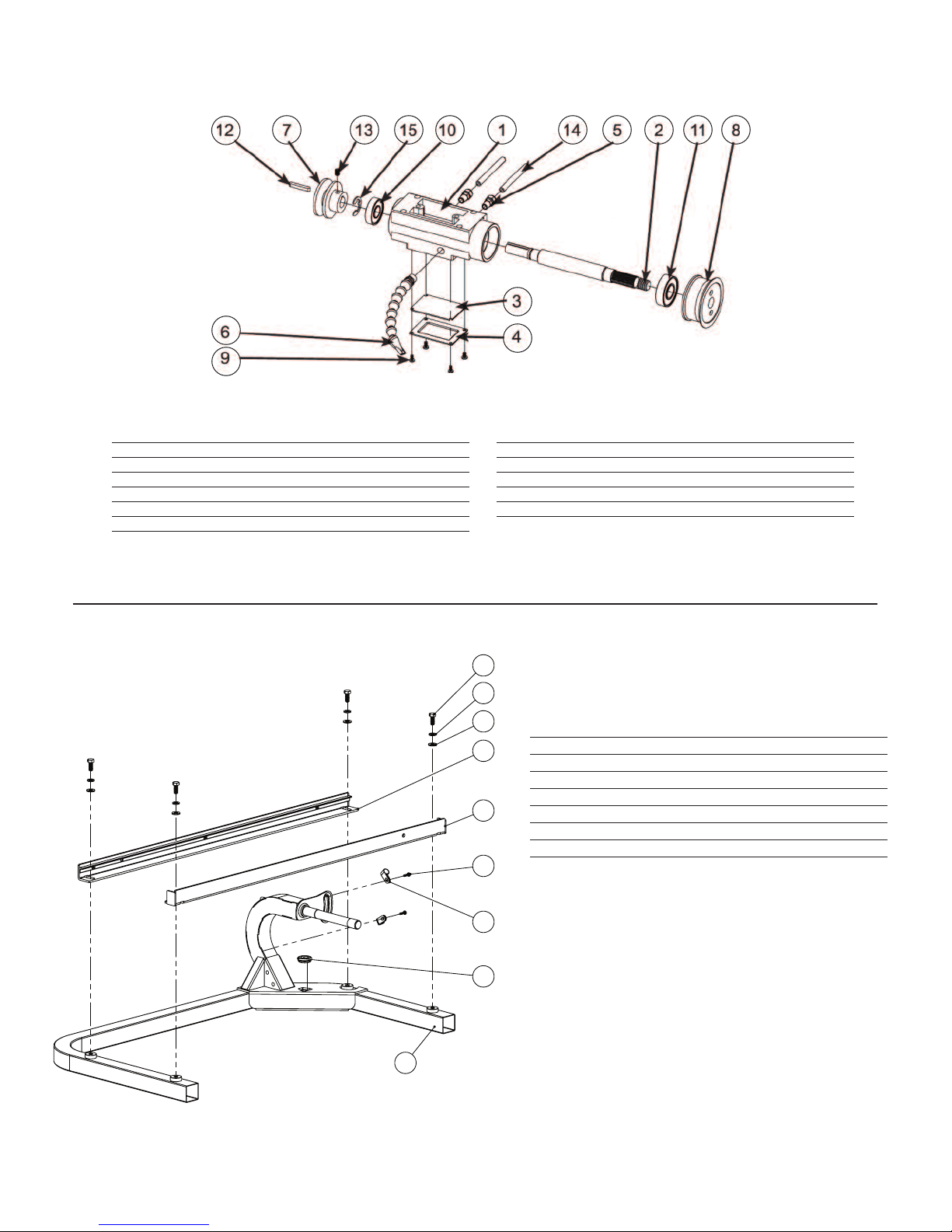
PA-10 LIQUID BEARING HOU ING A EMBLY
PA-10 FRAME A EMBLY
1 Frame weldment PA100204
2 843L L-Rail weldment PA100131
3 M8 Wide Washer (4) PA0120
4 M8 Spring Lock Washer (4) PA0121
5 M8 x 1.25 x 20L Hex bolt (4) CX38052
6 843L L-Rail weldment w/stop PA100205
7 D22.2 d17 10t rommet PA100206
8 ED127 D12 Hose clamp PA100207
9 M4 x 0.7 x 16L Cross screw (2) PA03531
PART NAME PART NUMBER
1 10" Variant LCBH ver2 (black) - Complete PA100202
2 Blade Shaft PA100112
3 Rubber asket PA100113
4 Water Channel Cover PA100114VX
5 M10 Male to D7.5 Male Connector PA100116
6 7 link 6.3 ID flat nose assembly PA100117
7 Blade Shaft Pulley PA100118
8 Dia 16.5 Arbor Inner Flange PA100119
9 M4 x 0.7 x 8L Cross Screw PA1374
10 D40 d17 6203LLB Radial Bearing PA100120
11 D47 d20 6204LLB Radial Bearing PA100121
12 5 x 5 x 30L Square Key PA100093
13 M6 x 1.0 x 10L Flat Point Set Screw PA100094
14 Water Hose (1 ft) PSV00040
15 M17 External E-Clip PA100124
PART NAME PART NUMBER PART NAME PART NUMBER
Table of contents
Other Pearl Saw manuals

Pearl
Pearl VX141MS User manual

Pearl
Pearl VX141MS User manual

Pearl
Pearl VX141MSD Owner's manual

Pearl
Pearl VX5WV Owner's manual

Pearl
Pearl PA-7 Owner's manual

Pearl
Pearl VX RSPRO VX1048RSPRO Owner's manual

Pearl
Pearl VX RSPRO R Owner's manual

Pearl
Pearl VX10RSPRO Owner's manual

Pearl
Pearl PA7TTR Owner's manual

Pearl
Pearl CX10 Owner's manual


