Pearl PA-7 Owner's manual
serial number -
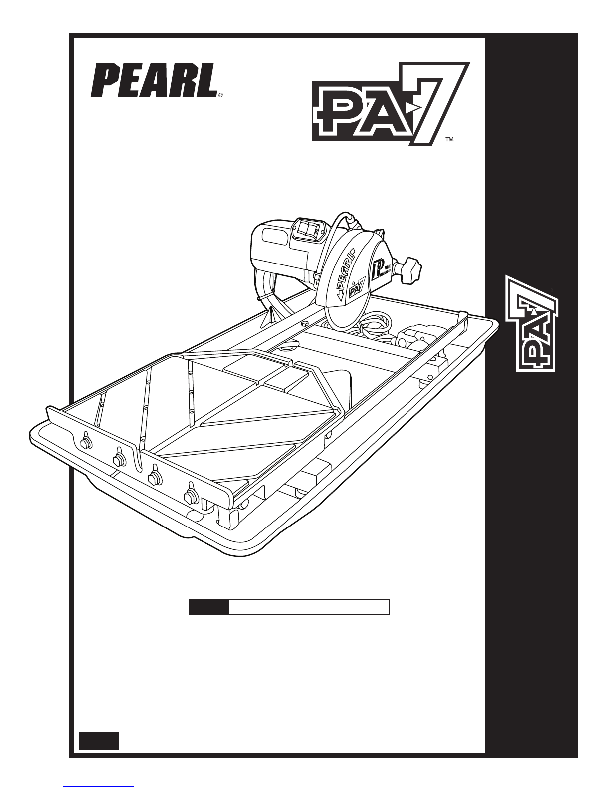
MODEL PA-7™ TILE SAW
Owner’s/OperatOr’s Man al
Caution! Read Safety and General Instructions carefully before using saw for the first ti e.
ou should record the Serial Number of your Tile Saw on this
Owner’s/Operator’s Manual and on the Warranty Card. The Warranty
Card ust be sent back with all the required pertinent infor ation
for the warranty to take effect.
Covered by one or more of the following US Patents:
6,080,041; 6,119,676; 6,272,990; 6,460,533; and D458,282
P e a r l A b r a s i v e C o . 2 . 1 T I L E S A W
REV. 3

TABLE OF CONTENTS
i. general saFetY r les FOr all pOwer tOOls . . . . . . . . . . . . . . . . . . . . . . . . . . . . . . . 3
ii. sYMBOls . . . . . . . . . . . . . . . . . . . . . . . . . . . . . . . . . . . . . . . . . . . . . . . . . . . . . . . . . . . . . . . . . . . 4
iii. Feat res . . . . . . . . . . . . . . . . . . . . . . . . . . . . . . . . . . . . . . . . . . . . . . . . . . . . . . . . . . . . . . . . . . . 5
iv. speCiFiCatiOns . . . . . . . . . . . . . . . . . . . . . . . . . . . . . . . . . . . . . . . . . . . . . . . . . . . . . . . . . . . . . 5
v. npaCKing . . . . . . . . . . . . . . . . . . . . . . . . . . . . . . . . . . . . . . . . . . . . . . . . . . . . . . . . . . . . . . . . 6
vi. installatiOn and OperatiOn . . . . . . . . . . . . . . . . . . . . . . . . . . . . . . . . . . . . . . . . . . . . . 6
vii. prOper Blade se . . . . . . . . . . . . . . . . . . . . . . . . . . . . . . . . . . . . . . . . . . . . . . . . . . . . . . . . . . 8
viii. saFe Operating praCtiCes FOr tile saw. . . . . . . . . . . . . . . . . . . . . . . . . . . . . . . . . . . . 9
ix. Care and MaintenanCe . . . . . . . . . . . . . . . . . . . . . . . . . . . . . . . . . . . . . . . . . . . . . . . . . . 12
x. eleCtriCal MOtOr speCiFiCatiOns . . . . . . . . . . . . . . . . . . . . . . . . . . . . . . . . . . . . . . . . 14
xi. replaCeMent parts list . . . . . . . . . . . . . . . . . . . . . . . . . . . . . . . . . . . . . . . . . . . . . . . . . . . 15
xii. trO BlesHOOting. . . . . . . . . . . . . . . . . . . . . . . . . . . . . . . . . . . . . . . . . . . . . . . . . . . . . . . . 18
xiii. aCCessOries and parts . . . . . . . . . . . . . . . . . . . . . . . . . . . . . . . . . . . . . . . . . . . . . . . . . . . 18
xiv. tHe rigHt Blades dOes tHe rigHt JOB . . . . . . . . . . . . . . . . . . . . . . . . . . . . . . . . . . . . . 19
xv. HOw tO Order parts. . . . . . . . . . . . . . . . . . . . . . . . . . . . . . . . . . . . . . . . . . . . . . . . . . . . . 19
page
– 3–
i. GENERAL SAFETY RULES FOR ALL POWER TOOLS
1. Know your power tool - read owner’s/operator’s manual carefully. Learn its applications and limitations as
well as the specific potential hazards unique to this tool.
2. Keep guards in place - and in working order.
3. Ground all tools - if tools are equipped with three prong plug, it should be plugged into a three-hole electrical
receptacle. If an adapter is used to accommodate a two-prong receptacle, the adapter lug must be attached
to a known ground. Never remove the third prong.
4. Remove wrenches - Form a habit of checking to see that adjusting wrenches are removed from tool before
turning it “on”.
5. Keep work area clean. Cluttered areas and benches invite accidents.
6. Do not use in dangerous environment. Do not use power tools in damp or wet locations, or expose them to
rain. Keep work area well lighted. Do not use tool in the presence of flammable liquids or gasses.
7. Keep children and visitors away. All children and visitors should be kept at a safe distance from work area.
8. Make workshop childproof with padlocks, master switches or by removing starter keys.
9. Do not force tool. It will do the job better and be safer at the rate for which it was designed.
10. Use right tool. Do not force tool or attachment to do a job for which it was not designed.
11. Wear proper apparel. Do not wear loose clothing, gloves, neckties, rings, bracelets or other jewelry that may
get caught in moving parts. Non-slip footwear is recommended. Wear protective hair covering to contain
long hair.
12. Always use safety glasses. Wear safety glasses (must comply with ANSI Z87.1) at all times. Everyday
eyeglasses only have impact resistant lenses; they are not safety glasses. Use face or dust mask if cutting
operation is dusty, and ear protectors (plugs or muffs) during extended periods of operation.
13. Do not overreach. Keep proper footing and balance at all times.
14. Maintain tools in top condition. Keep tools sharp and clean for best and safest performance. Follow
instructions for lubricating and changing accessories. Inspect tool cords periodically and if damaged, have
repaired by authorized service facility.
15. Disconnect tools. When not in use, before servicing, and when changing accessories, such as blades, bits,
cutters.
16. Avoid accidental starting. Make sure switch is in “off” position before plugging in power cord.
17. Use recommended accessories only. Consult the owner’s manual for recommended accessories. The use
of improper accessories may cause risk of injury to persons.
18. Never stand on tool. Serious injury could occur if the tool is tipped or if the cutting tool is accidentally
contacted.
19. Check Damaged Parts. Before further use of the tool, a guard or other part that is damaged should be
carefully checked to ensure that it will operate properly and perform it’s intended function. Check for
alignment of moving parts, binding of moving parts, breakage of parts, mounting, and any other conditions
that may affect it’s operation. A guard or part that is damaged should be properly repaired or replaced.
20. Never leave tool running unattended. Turn power “off”. Do not leave tool until it comes to a complete stop.
Read all instructions. As with all machinery there are certain hazards involved with
operation and use of the machine. The following asic safety precautions should e followed at all times to
reduce the risk of fire, electric shock and serious personal injury to you or others. Keep these important
operating instructions with this product.
WARNING!
– 4–
KEEP GUARD IN PLACE
DIAMOND BLADE
BLADE CUTTING DEPT
ELECTRIC SWITC OFF
ELECTRIC SWITC ON
ELECTRICAL AZARD
REMOVE TOOLS
PAY EXTREME
ATTENTION
REPAIRS TO BE DONE
MAC INE AZARD
FLAMMABLE
READ INSTRUCTIONS
CAREFULLY
WARNING
FRAGILE
KEEP DRY
DO NOT STEP ON
WEAR EARING
PROTECTION
WEAR EYE PROTECTION
WEAR BREAT ING
PROTECTION
WEAR ARD AT
WEAR PROTECTIVE
CLOT ING
WEAR SAFETY S OES
WELL VENTILATED
NO NON-WORKING
PERSONNEL
21. Extension cords. Make sure your extension cord is in good condition. When using an extension cord, be
sure to use one heavy enough to carry the current your product will draw. An undersized cord will cause a
drop in line voltage resulting in loss of power and overheating. Extension cord tables (refer to page 21) show
the correct size to use depending on cord length and nameplate ampere rating. If in doubt, use the next
heavier gage. The smaller the gage numbers the heavier the cord.
22. Do not abuse cord. Never carry tool by cord or pull it to disconnect from receptacle, Keep cord from heat,
oil, and sharp edges.
23. Guard against electric shock. Prevent body contact with grounded surfaces. For example, pipes, radiators,
ranges and refrigerator enclosures.
24. Outdoor use extension cords. When tool is used outdoors, use only extension cords intended for use
outdoors and so marked.
25. Stay alert. Watch what you are doing. Use common sense. Do not operate tool when you are tired.
26. Drugs, alcohol, medication. Do not operate tool while under the influence of drugs, alcohol or any
medication.
27. Store idle tool. When not in use, tool should be stored in a dry and locked place, out of reach of children.
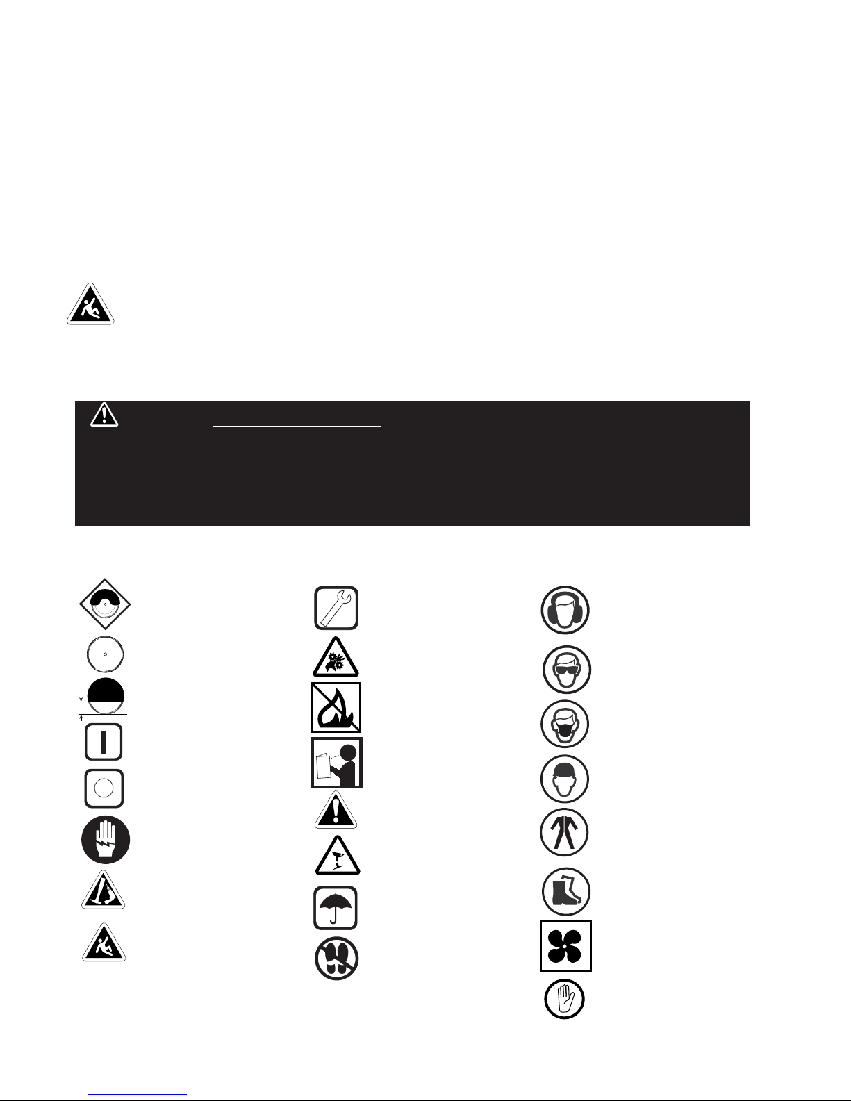
ii. SYMBOLS
CALIFORNIA PROPOSITION 65: Sawing and drilling generates dust. Excessive air orne
particles may cause irritation to eyes, skin and respiratory tract. To avoid reathing impairment always employ
dust controls and protection suita le to the material eing saw or drilled in accordance with OSHA (29 CFR Part
1910.1). Diamond lades improperly used are dangerous. Comply with ANSI Safety Code B7.1 and OSHA covering
speed, safety guards, flanges, mounting procedures, general operating rules, handling, storage and general
machine condition.
WARNING!
– 5––
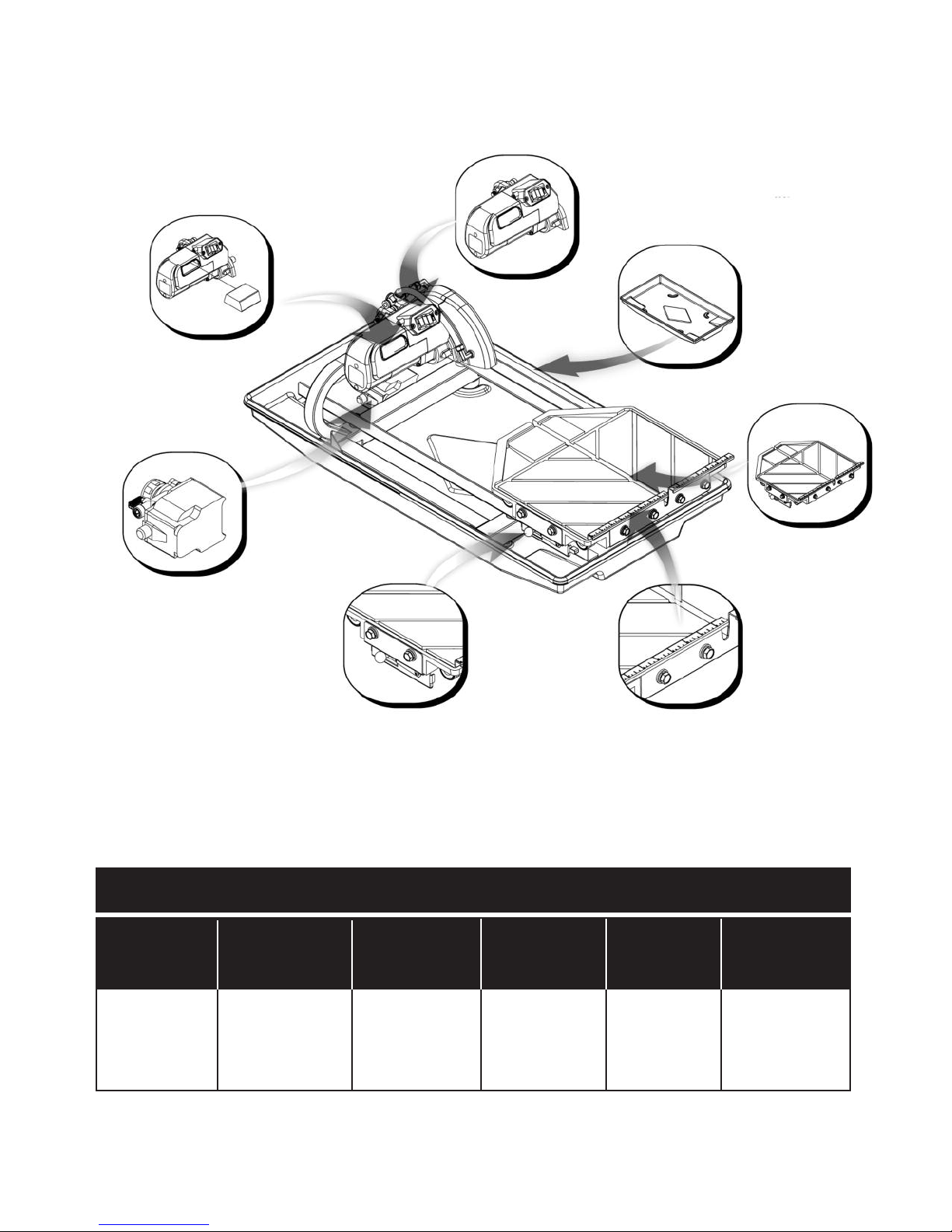
iii. FEATURES
REUSABLE AIR FILTER
Air intake to the motor is filtered
by a fire resistant filter, which
can be cleaned and reused.
3/4 HP BRUSH MOTOR
Generates more torque and is physically
smaller and lighter than similarly rated
induction motors.
STAINLESS STEEL
WATER TRA
igh durability tray
for heavy-duty jobs.
CUTTING TABLE
Provides a durable
work surface while
the ball bearing
wheels and rollers
ensure smooth
effortless
movement.
RULER GUIDE
The guide allows convenient
measurements and promotes
precision cuts.
TABLE RETENTION DEVICE
The device secures the cutting table
when transporting the saw.
WATER PUMP
A high-output water pump
provides sufficient water flow to
cool the blade.
PA-7 TILE SAW
MOTOR MAX. BLADE
CAPACITY
CUTTING
LENGTH
CUTTING
DEPTH WEIGHT
DIMENSIONS
iv. SPECIFICATIONS
7" Blade
5/8" arbor blade
20" rip cut,
14" diagonal cut
1-1/4" 40 lbs. 33.1" L
x 18.7" W
x 12.7"
3/4 P
115 v, 60 z,
6,000 rpm
– 6–
vi. INSTALLATION AND OPERATION
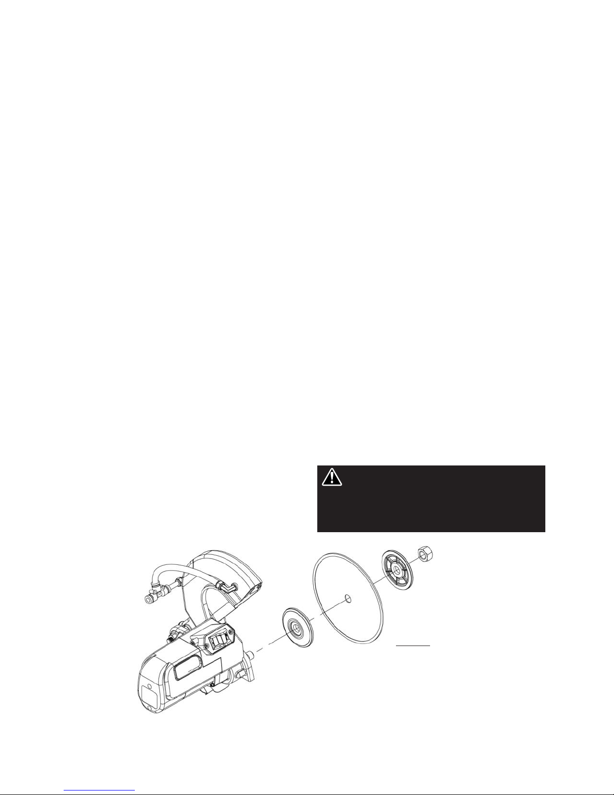
1. Loosen blade guard adjustment knob located at
the rear of the blade guard. Raise the blade
guard to the highest position and retighten the
knob.
2. Remove the blade shaft nut and outer flange.
(see figure 1) If a blade has been mounted,
hold the blade with one hand and use the other
hand to loosen the nut with the universal
wrench. Remove existing blade.
3. Mount new blade, but make certain the arrow
on the blade coincides with the rotation
direction of the shaft.
4. Attach outer flange and blade shaft nut. old
the blade with one hand and use the other hand
to tighten the nut with the universal wrench.
Make certain the flanges are pressed flush
against the blade and that the nut is firmly
tightened, but do not over tighten.
5. Loosen blade guard adjustment knob, lower the
blade guard and retighten the knob.
WARNING: nly use 7" blades on this saw.
Setting a smaller blade may cause the blade
to grab the material being cut, possibly
causing injury to the operator and the saw.
Figure 1
v. UNPACKING
Open the container and carefully lift the saw by the foam packaging and place it on a flat, level
working area. Be sure that you have the following items before you discard the container:
• Saw
• Stainless steel water tray
• 7" saw blade
• 45º/90º rip guide
• Universal wrench
• Water pump
• Owner’s manual
• Drain plug
BLADE INSTALLATION

– 7––
1. Remove the water pump from the box and
check that it is not damaged.
2. Place the pump within the water tray such that
the water outlet is horizontal. (see figure 2)
3. Connect the water hose from the blade guard to
the pump and plug the pump’s power cord into
the female plug that is attached to the post.
4. Fill the water tray so that the water intake is fully
immersed. Proper water level must be
maintained at all times during saw operation.
WARNING: Disconnect the pump before
attempting to handle the pump. Never
operate pump without water in the tray.
1. The ruler guide has inches marked along the top
to allow convenient measurements and to
promote precision cuts. (see figure 3)
2. The cast aluminum cutting table spans an area
of 14-1/2" x 14", which allows it to provide
greater support for handling larger materials.
3. A rip guide should be used together with the
cutting table to ensure precision while making
cuts.
1. Set the rip guide at the desired location on the
ruler guide and tighten the threaded knob.
Make sure that the rip guide is firmly tightened
to avoid slippage. The rip guide can be used for
45º and 90º cuts from both the left and right
side.
2. After the rip guide is positioned for the desired
cut, place material flat against the rip guide and
the ruler guide.
3. Now you are ready to make your cut.
1. Remove threaded knob from the end of the rip
guide with the horizontal groove and insert it
into the other end with the diagonal grooves.
2. Position the rip guide along either of the
diagonal premarked lines that intersect the
ruler guide and the vertical channel of the
cutting table. Tighten threaded knob once in
place.
3. Place one corner of the material being cut in the
vertical slot of the ruler guide and rest the
adjoining edge flat against the rip guide.
4. Now you are ready to make your cut.
To make miter cuts, an optional miter block must
be purchased.
1. Place the lip of the miter block on the ruler
guide with the threaded knob facing you.
2. Position the miter block such that a tile laying
flat against the block may rest its left-most
edge within the vertical channel of the cutting
table. Tighten the threaded knob to secure the
miter block in place.
3. Place material onto miter block and you are
ready to cut.
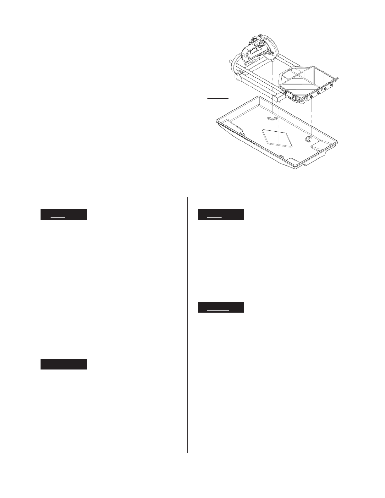
1. Lift the saw up from inside the water tray.
2. Remove the drain plug and drain any water left
inside the water tray.
Figure 2
Figure 3
WATER PUMP INSTALLATION USING THE RIP GUIDE
PERFORMING DIAGONAL CUTS
PERFORMING MITER CUTS
CLEANING THE WATER TRAY
USING THE CUTTING TABLE
– 8–
3. Flush water into the tray while holding it upright to
remove any sludge buildup.
4. Replace the saw back into the tray. (see figure 4)
5. Reinstall the drain plug into the drain hole before
filling the tray with water.
1. Ensure that the water tray is empty and dry.
2. Unplug the power cord and store it in the
water tray.
3. Secure the cutting table to the front of the saw
using the table retention device.
D ’S
• Inspect blades daily for cracks or uneven wear.
• Always use appropriate blade for material
being cut.
• Inspect arbor shaft for uneven wear before
mounting blade.
• Always use blades with the correct arbor shaft
size.
• Ensure that blade is mounted in the correct
direction.
• Use proper safety equipment when operating
the saw.
• Always have a continuous flow of water on
both sides of blade.
• Secure the blade to the arbor with a wrench.
D NT’S
• Do not operate the saw without safety guards
in position.
• Do not operate the saw with blades larger or
smaller than 7".
• Do not cut dry with blades marked “Use Wet”.
• Do not exceed manufacturer’s recommended
maximum RPM.
• Do not force blade into material. Let blade cut
at its own speed.
D ’S
• In addition to the following, always follow wet
recommendations.
• Use appropriate blade for material being cut.
• Inspect segment blades for segment cracking
or loss.
• Do not use damaged blades.
• Use proper safety equipment when operating
the saw.
D NT’S
• In addition to the following, always follow wet
recommendations.
• Do not make long cuts with dry blades. Allow
them to air cool.
• Do not use the edge or side of blade to cut or
grind.
• Do not attempt to cut a radius or curve.
• Do not cut too deep or too fast into the
material.
• Do not cut any material not recommended by
blade manufacturer.
TRANSPORTING THE SAW
WET CUT BLADES DRY CUT BLADES
Figure 4
vii. PROPER BLADE USE

– 9––
viii. SAFE OPERATING PRACTICES FOR TILE SAW
1. Use safety equipment - wear safety approved
hearing, eye, head and respirator protection.
2. Read and understand the symbol definitions
contained in this manual.
3. Read and understand all warnings and
instructions on the machine.
4. Read all safety materials and instructions that
accompany any blade or accessory used with
this machine.
5. Establish a training program for all operations
of this machine.
6. Always provide a copy of this manual to the
equipment user. If you need extra copies
call our Customer Service Department at
1-800-969-5561.
7. Always select a diamond blade according to
the manufacturers recommendation suitable
for the material to be cut. Never use a blade
having a maximum operating speed lower than
the “No load R.P.M.” marked on the tool
nameplate. Do not operate any saw without
safety guards in place or with a blade diameter
larger than the maximum saw blade capacity.
8. Before mounting a blade on the saw clean and
inspect the arbor shaft, blade flanges and the
diamond blade for uneven wear or damage. If
it appears to be damaged, Do not operate the
tool. ave it serviced by a qualified service
technician.
9. Before each use of the saw, inspect the
diamond blade for hairline fatigue cracks. If
such a crack or flaw is evident, discard the
blade. Using a damaged lade may cause
injury to the operator or others.
10. Be sure that the blade arbor hole matches the
blade adapter flange supplied with the saw.
Use only blade adapter flanges that came on
your saw. Never use damaged or worn blade
adapter flanges.
11. Installing the blade, install the blade with the
arrow pointing the same direction as the
rotation of the arbor shaft or the arrow on the
blade guard. Be sure to tighten the blade shaft
arbor nut with the wrench provided.
Be careful not to over tighten.
12. Check that the blade tracks near the center of
the channel in the main table, and that the table
moves freely from front to back.
13. Sometimes the material being cut is not
abrasive enough to expose new diamonds on
the blade. If the blade is not sharpened, it will
rub against the surface resulting in heat build
up in the core. To prevent this, it is necessary
to dress the blade. To dress the blade simply
cut something that is very abrasive such as a
piece of cement block. Indications that the
blade needs dressing includes:
• The diamond in the matrix appear shiny
because they are worn flat.
• The blade stops cutting or noticeably
slows down.
Blade dressing stones are available from your local Pearl
Warehouse.
14. Before using the saw fill the water tub enough
to submerge the water pump with clean water
only. Replenish as necessary and clean the
water tub frequently. Do not operate a wet
cutting blade without adequate water flow to
both sides of the blade. Never run the pump
dry.
15. When cutting, always hold the material firmly
lying flat, supported by the main table with one
edge resting against the main table backstop.
The dust generated y cutting
of tile, mar le, stone, ricks etc. can e injurious
to your health. Always operate machinery in well
ventilated areas and provide proper dust removal.
Always wear a dust mask approved for respiratory
protection against these types of dusts and mists.
For your own safety and the
safety of others do not attempt to operate this saw
until you have read and understand the general
safety rules for all power tools and the following
additional safety precaution unique to this saw.
WARNING!
WARNING!
Not dressing the lade
frequently or setting the lade too high will cause
it to gra the tile possi ly causing injury to the
operator and the saw. Setting the lade depth too
low will cause it to cut into the main ta le that
may result in injury.
WARNING!

– 10 –
• Do not attempt to cut pieces too small to
safely hold down on the main table.
• Never use the side of the blade to cut or
grind with, only cut in a straight line.
• Keep all parts of your body away from the
blade and all other moving parts.
• Never touch or try to stop a moving blade
with your hand.
16. When cutting dry - always unplug the water
pump first. Never run the pump dry.
• Do not use a wet cutting blade for dry
cutting. Select the proper dry cutting
blade for your application.
• Never make long continuous cuts with dry
cutting blades. To avoid heat build up,
allow the blade to cool, remove the tile
and allow the blade to run freely for a few
minutes.
IMPORTANT - If there is any tendency for the
saw to tip or ove during certain operations,
such as when cutting large heavy tile; the saw
ust be securely fastened to a supporting
table.
17. Make certain all adjusting knobs or locks are
tight and engaged in their detents and that
movable parts not intended to move during
operation are securely locked before making a
cut. Be careful not to over tighten.
18. Before connecting the machine to a power
source check to see that the “On/Off” switch is
in the “off” position.
• Make sure the blade is not contacting
anything before connecting to a power
source and starting the motor.
• Know how to stop the machine quickly in
case of an emergency.
19. Grounding Instructions
• In the event of a malfunction or
breakdown, grounding provides a path of
least resistance for electric current to
reduce the risk of electric shock. This tool
is equipped with an electric cord having
an equipment-grounding conductor and a
grounding plug. The plug must be
plugged into a matching outlet that is
properly installed and grounded in
accordance with all local codes and
ordinances.
• Do not modify the plug provided - if it will
not fit the outlet, have the proper outlet
installed by a qualified electrician.
• Improper connection of the equipment-
grounding conductor can result in a risk
of electric shock.
• Check with a qualified electrician or
service personnel if the grounding
instructions are not completely
understood, or if in doubt as to whether
the tool is properly grounded.
• Use only 3 wire extension cords that have
3 prong grounding plugs and 3 pole
receptacles that accept the tool’s plug.
Repair or replace damaged or worn cord immediately.
This tool is intended for use on a circuit that has an outlet
that looks like the one illustrated in Figure 5. The tool has
a grounding plug that looks like the plug illustrated in
Figure 5(A). A temporary adapter, which looks like the
adapter illustrated in Figure 5(B) and 5(C), may be used
to connect this plug to a 2 pole receptacle as shown in
Figure 5(B) if a properly grounded outlet is not available.
The temporary adapter should be used only until a
properly grounded outlet can be installed by a qualified
electrician. The green-colored rigid ear, lug, and the like,
extending from the adapter must be connected to a
permanent ground such as a properly grounded outlet
box.
Note: USE OF A TEMPORARY ADAPTER IS NOT
PERMITTED IN CANADA.
Additionally, water pump requires the use of a Ground
Fault Circuit Interrupter. Therefore, when using the water
pump receptacle, this tool must be plugged into a
properly installed Ground Fault Circuit Interrupter outlet.
See Figure 5(D). If a Ground Fault Circuit Interrupter
outlet is not available, Pearl Abrasive Co. has it available
as an accessory item. A plug-in Ground Fault Circuit
Interrupter may be plugged into a properly installed and
grounded 3-pole outlet. Refer to Figure 5(E).
20. Position of the Tile Saw
• To avoid the possibility of the appliance
plug or receptacle getting wet, position
tile saw to one side of a wall mounted
NOTE - Use of a Te porary Adapter is not per itted
in Canada.

– 11 –
receptacle to prevent water from dripping
onto the receptacle or plug. The user
should arrange a “drip loop” in the cord
connecting the saw to a receptacle. The
“drip loop” is that part of the cord below
the level of the receptacle, or the
connector if an extension cord is used, to
prevent water traveling along the cord and
coming in contact with the receptacle. See
Figure 6.
• If the plug or receptacle does get wet,
Do not unplug the cord. Disconnect the
fuse or circuit breaker that supplies power
to the tool. Then unplug and examine for
presence of water in the receptacle.
21. Extension Cords
• Use only extension cords that are
intended for outdoor use. These extension
cords are identified by a marking
“Acceptable for use with outdoor
appliances; store indoors while not in
use.” Use only extension cords having an
electrical rating not less than the rating of
the product. Refer to chart on page 14.
Do not use damaged extension cords.
Examine extension cord before using and
replace if damaged. Do not abuse
extension cords and do not pull on any
cord to disconnect. Keep cord away from
heat and sharp edges. Always disconnect
the extension cord from the receptacle
efore disconnecting the saw from the
extension cord.
* Ground Fault Circuit Interrupter (GFCI)
protection should be provided on the
circuit(s) or outlet(s) to be used for the
tile saw. Receptacles are available having
built-in GFCI protection and may be used
for this measure of safety.
(A) (B)
Figure 5
Grounding Methods
(C) (D) (E)
Grounding pin
Grounding pin
Cover of
grounded
outlet box
Metal
Screw
Grounding
Means
(Lug)
To reduce the risk of electrocution, keep
all connections dry and off the ground.
Do not touch plug with wet hands.
TOOL
Figure 6
Drip Loop
Supporting
Surface
Power Cord
Drip Loop

– 12 –
ix. CARE AND MAINTENANCE
For your safety efore performing any maintenance on the saw turn off the power switch
and unplug the power cord.
WARNING!
GENERAL RULES
• Always clean the machine before performing any
maintenance/ repair.
• Before performing any cleaning/maintenance
/repair, the machine must be switched off with the
main power switch.
Steps to Follow When Cleaning:
• Please do not use aggressive cleaners (i.e.
containing solvents). Do not use high-pressure
water jets, aggressive detergents or solutions and
liquids with a temperature exceeding 86ºF! Use a
fluff-free cloth only.
• Use a cloth which may be lightly moistened only for
removing dust and dirt. ard packed dirt can be
removed with a soft brush.
• For the sake of safety, no water/cleaning
liquid/vapor may penetrate into the electric motor,
connectors/plugs, switches, etc. Therefore cover
all apertures, holes in the housing, connectors or
plugs, etc. or seal them with adhesive tape!
• Use a soft, low-pressure water jet and a brush to
rinse dirt and incrustations away. Be particularly
careful when near hazardous parts of the machine
(e.g. switch, motor). Clean the motor and switches
only by wiping with a moist cloth.
• Do not “rinse” the bearings of the drive elements to
prevent them from running dry. The ball bearings
of the machine are permanently lubricated.
• After cleaning, remove all covers and adhesive
tape! All screws/nuts which you may have
loosened must be tightened again!
• After wet cleaning, try the machine on a power
outlet which is equipped with a power breaker (i.e.
fault current circuit breaker). If the fault current
circuit breaker cuts the power supply, the machine
must be inspected by an authorized dealer prior to
use!
CLEANING
After every use of the machine:
• Remove dirty water from container.
• Remove dirt and mud from the bottom of the
container.
• Rinse the immersion pump with fresh water to
prevent the water pump from clogging with
residual dirt.
After wet cleaning and before using the machine
again:
• Connect the machine to an electric power outlet
equipped with a “GFCI” safety power breaker. If the
safety power breaker cuts off the electrical power
supply, do not try to operate the machine but have
it checked by an authorized dealer first.
PROLONGED PERIOD OF NON-USE
Before not using the machine for a prolonged period
of time:
• Clean and lubricate all movable parts. owever, do
not grease the guide rails.
After not using the machine for a prolonged period of
time:
• Check that the stand is safely fixed.
• Check that all screw joints and nuts are fixed.
• Check that the cutting table is seated properly on
the guide rails and that it moves easily along the
entire length of the rails.
• With the saw blade removed, switch on the motor
for an instant and switch it off again. If the motor
does not run, have the machine inspected by a
qualified electrician.
• Check that the immersion pump works properly.
Turn on the cooling water tap and switch the
machine on. If the pump does not give any water or
only a little, switch the machine off at once. Clean
the pump, or replace if necessary.
EXTREME TEMPERATURE
Ambient temperature below 32° F (Winter):
• To prevent the water in the pump and cooling
system from freezing, remove the water after using
the machine or when there will be a long break.
Make sure that the cooling system is entirely
drained so that there is no water left inside the
pump and water hose!
– 13 –
WATER PUMP MAINTENANCE
When the machine has not been used for a long period of
time, hard packed dirt may begin to build up inside the pump
and block the pump wheel. If the machine is activated with
the immersion pump blocked, the electric motor of the
pump will be damaged within a few minutes! Please follow
the steps listed below to clean the pump before operating
the saw:
1. Remove the immersion pump from the water container.
2. Clean the immersion pump.
3. Loosen the fixing screws of the pump lid.
4. Take the lid off the pump. Be careful not to damage or
lose the gasket underneath.
5. Clean the pump lid.
6. Remove all dirt and incrustations from the pump wheel.
7. Check whether the pump wheel can be easily turned.
8. Then reassemble the immersion pump correctly and
check whether it works properly.
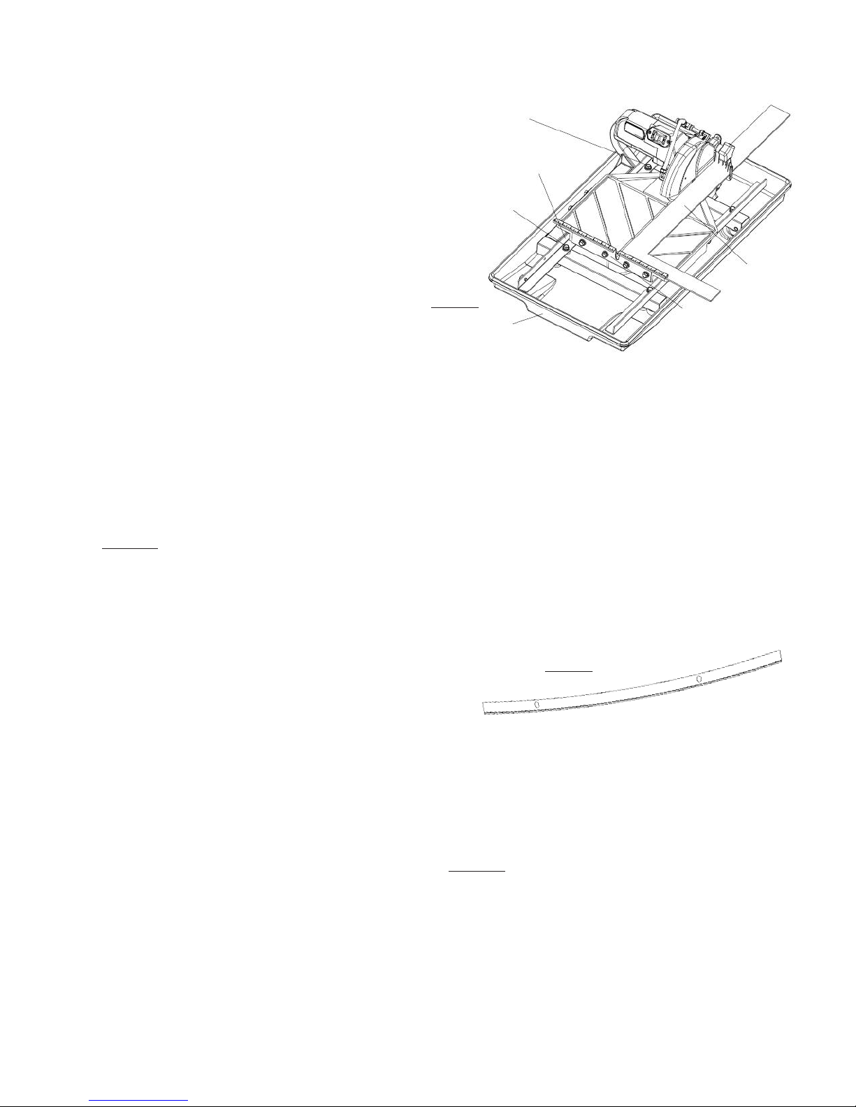
REALIGNMENT
Method 1:
This procedure deals with the most common source of
misalignment that occurs when the guide rails are not
parallel with the blade.
1. Place a straight edge on the cutting table as shown in
figure 7.
2. Loosen the left guide rail by untightening the fasteners
found at the ends of the rail. (see figure 7) Do not loosen
the rail too much to avoid excessive play during
adjustments.
3. Make sure the straight edge is placed flush against the
ruler guide. Adjust the left guide rail so the front and rear
edges of the blade touch the straight edge, although a
tolerance of 0.1mm between the front and rear edges is
allowed. Perform this adjustment along the entire length
of the straight edge.
4. Position the table as close to the user as possible. Place
the straight edge flush against the ruler guide and blade.
While gently holding down the straight edge, move the
table towards the rear of the saw and then back. Apply
just enough force to prevent the straight edge from
moving due to table vibrations, but not enough to prevent
the blade from displacing the straight edge. Observe any
gaps that may appear between the straight edge and
blade or between the straight edge and ruler guide. A gap
exceeding the allowed tolerance means that the table is
not moving parallel to the blade; hence, further
adjustments as outlined in step 3 will be required.
owever if scenario A or B described below occurs, other
adjustments may be required instead.
A. If the straight edge only touches the blade when
the table is positioned midway along the rail or at
the ends of the rail, then the left rail may be
deformed (i.e. bowed). (see figure 8) Typically a
bowing displacement of up to 0.2mm will not affect
cutting accuracy. Perform test cuts to determine if
the rail should be replaced. If a replacement is
required try swapping the left rail with the right rail
and perform the alignment procedure again. If this
does not solve the problem, then replacement rails
will have to be acquired.
B. If the straight edge touches both edges of the blade
intially, but shifts apart as the table travels along
the rail, proceed to method 2 below.
5. Tighten the fasteners at both ends of the left rail. If
alignment has been achieved do not proceed to
method 2.
Method 2:
This procedure corrects another source of misalignment
that occurs when the table’s orientation is not parallel with
the guide rails.
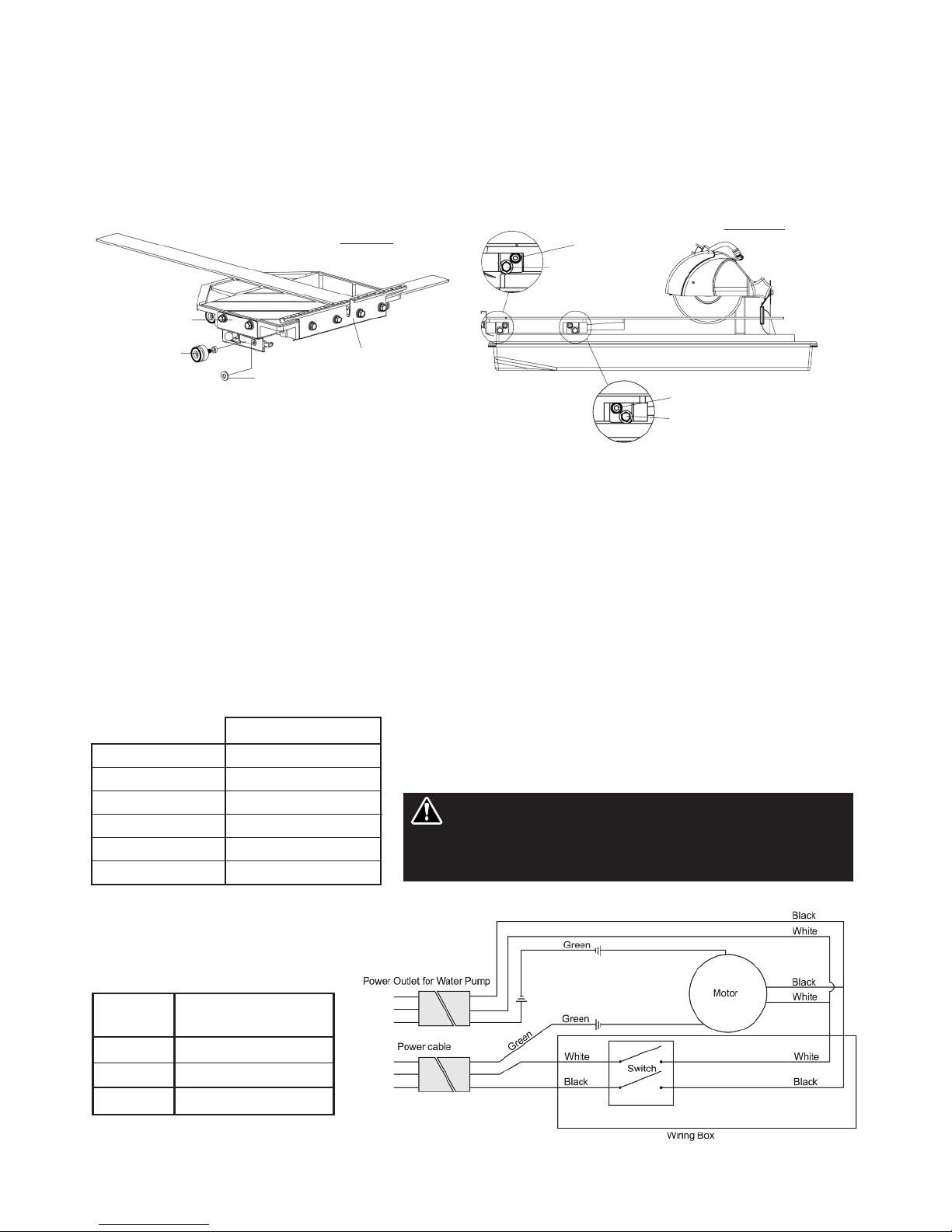
1. Lower the table bracket by loosening the two affixed
bolts. (see figure 9) Remove the table from the rails.
2. If the table shifts to the right as it travels away from the
user, a shim needs to be added to the guide roller furthest
Figure 7
Figure 8
Fastener
Fastener
Front
Straight
Edge
Ruler
Guide
Left Guide Rail
Straight
Edge
– 14 –
x. ELETRICAL MOTOR SPECIFICATIONS
from the ruler guide. On the other hand, if the table shifts
to the left, a shim needs to be added to the guide roller
closest to the ruler guide. Remove the appropriate guide
roller to insert a shim between the roller and table, then
reattach. (see figure 9) Depending on the severity of the
shift, more than one shim may be required.
3. After adding shim(s), mount the table onto the guide rails
and realign the table to the blade using method 1. Check
to see if any shifting persists. A shift tolerance of 0.2mm
is allowed. A shift in excess of that will require further
adjustment—repeat step 2.
4. Once alignment is successful, restore the table bracket to
its original position and secure it in place by tightening
the affixed bolts.
LEVELING ADJUSTMENT
This procedure levels the table so that it is perpendicular to
the blade and flush against the rails.
1. Loosen the bolt on the flat roller plate so that the roller
can swing freely about the bolt. (see figure 10) Do this for
both flat roller plates.
2. old the table against the rails. The flat rollers should
reposition themselves to maintain contact with the rails.
If the table is not perpendicular to the blade, lift the right
side of the table instead to obtain the proper angle. A
square tool will be required to confirm the angle. Tighten
the bolts. Check the table for play. Repeat step 1 if some
play is still present.
Figure 9 Figure 10
Ruler Guide
Bolt
Bolt
Flat Roller
Flat Roller
Shim
Guide Roller
Table Bracket
Horse Power 3/4 hp
Volts 115 V/ 60hz
Amps 7.5 amps
Motor RPM 6,350 rpm
Cycle 60
Phase 1
PA-7 TILE SAW
WIRE
GAUGE
No. 12
No. 10
No. 8
LENGTH F C RD
25'
50'
75'
Recommendations:
• It is recommended that a 7.5 amp circuit be used while operating this
saw. This will prevent possible power interruption or loss.
• Always plug saw as close as possible to the power source while
operating. This will allow you to receive optimum electricity.
Electrical Wiring Diagram
WARNING: To avoid permanent motor damage you must use
the correct extension cord. Never use more than one extension
cord at a time. Follow the chart for proper size.

– 15 –
xi. REPLACEMENT PARTS LIST
pa-7 C tting taBle asseMBlY
1 20 19
145166152
10718817162021
9
21
20
16
12 4 13 11 3
1 TC02 cutting table PA00001
2 Ruler guide PA00002
3 D12.7 d8.5 x 6L spacer PA00003
4 Type 6 guide ruler PA00004
5 Teflan flat ruler PA00005
6 Roller mounting plate PA00006
7 Table lock bracket PA00007
8 Leaf spring PA00008
9 Ball handle PA00009
10 Pin head PA00010
11 M22 Internal C-clip PA00011
12 M8 x 1.25 x 30L Socket head bolt PA00012
13 608 LLU radial bearing PA00013
14 M8 x 1.25 x 35L ex bolt PA00014
15 M8 x 1.25 nut PA00015
16 M8 narrow washer PA00016
17 M4 x 0.7 x 8L Cross screw PA00017
18 M4 x 0.7 Nylon nut PA00018
19 M8 x 1.25 x 20L socket head hex bolt PA00019
20 M8 Spring washer PA00020
21 M8 x 1.25 x 20L ex bolt PA00021
22 M8 x 1.25 x 25L Socket head hex bolt PA00022
PART NAME PART NUMBER PART NAME PART NUMBER

– 16 –
pa-7 MOtOr asseMBlY
14
68
18
19
20
27
16
32
29
30
12
13
24
33 39 9
42 15
36
35
17
21
7
36
40
28
38
2
39
43
24
41
37
17
21511
34
4
1
23222510
37
36
44
37
21
17
45
46

– 17 –
pa-7 MOtOr asseMBlY pa-7 Main asseMBlY
1 Blade shaft gear PA00023
2 Cutting head housing PA00024
3 Cutting head mounting tube PA00025
4 Blade shaft PA00026
5 Gear cover PA00027
6 Blade guard mounting shaft PA00028
7 Wire anchor plate PA00029
8 Wire separation plate PA00030
9 Wire access plate PA00031
10 Particle filter PA00032
11 D28 d20mm Oil seed PA00033
12 Complete Motor PA17101Z
13 14mm x 6mm Carbon brush PA00035
14 Anchor plate PA00036
15 Rubber Stop 22mm x 8mm x 2.5mm PA00037
16 M10 x 1.5 Nut PA00038
17 M4 Spring washer PA00039
18 M3 Narrow washer PA00040
19 M3 Spring washer PA00041
20 M3 x 8L Cross tapping screw PA00042
21 M4 Narrow washer PA00043
22 M15 External C-clip PA00044
23 5 x 16-Rad. Woodruff key PA00045
24 Dia 5/8'' (15.9mm) Universal flange PA00046
25 D19 d6 Radial bearing 626ZZ PA00047
26 KEDU KJD17B Electromagnetic switch PA00048
27 2 Cable D9 cable boot PA00049
28 Power switch mounting plate PA00050
29 M8 Narrow washer PA00051
30 M8 Spring washer PA00052
31 M8 x 1.25 x 15L socket head hex bolt PA00053
32 M8 Rectangular shim PA00054
33 M8 x 1.25 x 15L flat point set screw PA00055
34 D35 d15 Radial bearing 6202 LLB PA00056
35 M4 x 8L Cross tapping screw PA00057
36 M4 x 5L Countersunk tapping cross screw PA00058
37 M4 x 20L Cross tapping screw PA00059
38 Gasket PA00060
39 M4 x 1.25 Acorn nut. PA00061
40 20A 125V/12A 250V Toggle switch CX38085
41 7'' blade
42 M8 x 1.25 Nut PA00062
43 5/8'' - 11 UNC Nut PA00063
44 Motor fan cover assembly PA00064
45 Water pump receptacle PSV10033R
46 Power cable S710-01
PART NAME PART NUMBER
1 Frame weldment PA00067
2 Left 755L - L-rail PA00068
3 Right 755L - L-rail PA00069
4 Steel water tray assembly PA00070
5 1/2 P Cutting head PA00071
6 TC02 Cutting table PA00072
7 Water pump CX38011
8 Water flow T adapter PSV00005
9 M10 Spring washer PA00073
10 M4 Spring washer PA00074
11 M8 Spring washer PA00075
12 M4 x 0.735L Cross screw PA00076
13 Male M8 x 1.25 x 20L knob PA00077
14 M8 Narrow washer PA00078
15 M8 x 1.25 x 20L ex bolt PA00079
16 M4 x 0.7 Nut PA00080
17 Rubber stop PA00081
18 Rubber splash guard PSV100023
19 M6 Narrow washer PA00082
20 M6 x 1.0 x 10L ex bolt PA00083
21 Blade guard PA00084
22 Water flow L adapter PSV00008
23 Air FIlter PA00085
24 20A 125V 12/250V Toggle Switch CX38085
25 Drain Plug S1000-48
PART NAME PART NUMBER
20
5
6
3
2
15
11
14
16
17
12
20
1
4
19 18 8 9 13
21
22
24
23
7
25

– 18 –
xiii. ACCESSORIES & PARTS
Name (Qty.)
Stainless Steel Water Tray (1)
Drain plug not included
Part Number
PA00072
Name (Qty.)
Optional Universal
Saw Stand (1)
Part Number
V35010-UV
Name (Qty.)
Optional Complete
Miter Block with
Knob (1)
Part Number
S1000-34
Knob Only (1)
V35016
Knob Only (1)
V35016
xii. TROUBLESHOOTING
For your safety and the safety of others, turn the power switch off and always remove the plug from
power source efore trou leshooting. Repairs performed y unauthorized personnel could cause serious hazard. We
recommend that service to this tool e performed y a qualified service technician with original equipment replacement parts.
WARNING!
EXCESSIVE N ISE. Possible blade shaft bearing wear,
motor belt loose or motor fan rubbing on housing. ave
tool serviced.
BLADE WILL N T CUT. Check for worn out diamond edge.
Be sure that the arrow on the blade is rotating the same
direction as the motor arbor and/or arrow on the blade
guard. Make sure the blade is suitable for the material to be
cut. If blade has been used to cut a material that is hard, it
may have become dull, dress the blade by cutting a light
weight abrasive building block to expose fresh diamonds.
Blade dressing stones are available from your local Pearl
Warehouse.
M T R WILL N T START. Check power supply. If the
water pump turns on when the power switch is in the “on”
position, but the motor does not, have the motor serviced.
M T R WILL N T ST P. The contacts in the switch may
have become arched together in the on position, have it
serviced.
M T R SHUTS FF DURING PERATI N. Check to see
that the circuit you are using is not overloaded with lights
or other equipment. The fuse or circuit breaker may not
have sufficient capacity, use 20-amp power. If you are
using an extension cord check the extension cord table to
be sure it is heavy enough to carry the current this product
will draw. See Page 14 for electric cord reference.
EXCESSIVE VIBRATI N Check to see that the blade is
mounted properly according to safe operating practices
section. Blade may be out of balance, try a different blade.
Arbor shaft bearings possibly worn, have tool serviced.
N T CUTTING SQUARE. Check the main table and carriage
adjustment as well as the blade alignment procedure
located in the care and maintenance section.
MAIN TABLE D ES N T M VE FREELY. Inspect the guide
rails and rollers for build up of tile chips or dry slurry
deposits. Clean and check guide roll or adjustments,
according to the procedure in the care and maintenance
section.
N WATER FL W T BLADE. Check the water feed tube for
kinks or obstructions. Check the inlet screen to ensure it is
not clogged. Remove the pump inlet and turn the impeller
to ensure it is not damaged or jammed. Clean the impeller
if necessary and apply a drop of light oil to the shaft - be
sure the impeller spins freely.
P R MACHINE PERF RMANCE WITH LITTLE P WER.
Check cord/extension cable for appropriate length and gage.
Check power network for sufficient power and circuit
breaker capacity.
CENTER H LE IN BLADE VERSIZE R W RN. Saw blade
has slipped on shaft while running. Check shaft for damage
and replace blade.
Name (Qty.)
Complete 45˚/90˚
Rip Guide with
Knob (1)
Name (Qty.)
Complete 45˚/90˚
Rip Guide with
Knob (1)
Part Number
V35000

– 19 –
xv. HOW TO ORDER PARTS
Please have the following information ready before calling:
• Serial Number of your Tile Saw
• Model Number of the Tile Saw
• When purchased and where
• Part Description
All parts listed may be ordered from your Local warehouses. If the part is not stocked locally, call our Corporate
office and ask for our Customer Service Department. For Technical Support call 1-800-969-5561. In Canada call
1-800-387-0008. There is a $25.00 minimum order.
Return Policy: Return goods for credit or exchange on the basis of the following terms: (1) They must be current
products; (2) Items returned for replacement or refund should be in original cartons and must be accompanied
by a packing slip with the following information: Returned Goods Authorization (RGA) number obtainable from
Customer Service Department • List of items returned • Reason(s) for return(s) • Copy of original invoice(s); (3)
Freight charges must be assumed by sender; (4) Returning goods are subject to a 15% handling charge to cover
our cost of repacking and restocking. All Prices are subject to change without notice.
Disclaimer: Pearl Abrasive Co. reserves the right to make changes or improvements on its products without
incurring an additional obligation including any obligation to make corresponding changes or improvements to
products previously manufactured or sold. Pearl reserves the right to discontinue products at any time without
notice.
All illustrations displayed in this manual are the property of Pearl Abrasive Co. and shall not be duplicated or
reproduced without the express written consent of Pearl Abrasive Co.
xiv. THE RIGHT BLADE DOES THE RIGHT JOB
For the most effective cutting and blade life always use the recommended Pearl Abrasive Co. blade.
APPLICATION
PEARL BLADE
SERIES
HPXL Series
DTLB19 Series
HP Series
Glass Bla e
SH Series
Pro-V Series
CERAMIC EXTRA HARD PORCELAIN MARBLE GRANITE HARDSTONE GLASS TILE
TILE CERAMIC

Part No. PA7MAN • 04/14
GEORGIA • USA
4963 SOUT ROYAL ATLANTA DRIVE
TUCKER, GEORGIA 30084
ONTARIO • CANADA
375-2 PIDO ROAD
PETERBOROUG , ONTARIO K9J-6X7
C RP RATE FFICE: S . CALIF RNIA • USA
6832 E. SLAUSON AVENUE, COMMERCE, CA 90040-0031
562-927-5561 • FAX 562-928-3857
Toll Free: 800-969-5561
www.pearlabrasive.com
Table of contents
Other Pearl Saw manuals

Pearl
Pearl VX10.2XLPROR Owner's manual

Pearl
Pearl VX141MS User manual

Pearl
Pearl CX10 Owner's manual

Pearl
Pearl VX RSPRO R Owner's manual

Pearl
Pearl VX5WV Owner's manual

Pearl
Pearl PA-10 User manual

Pearl
Pearl PA7TT Owner's manual

Pearl
Pearl VX RSPRO VX1048RSPRO Owner's manual

Pearl
Pearl VX10RSPRO Owner's manual

Pearl
Pearl VX141MS User manual


