Pearl VX141MSD Owner's manual

serial number -
MODEL VX141MS™
MASONRY/BRICK SAW
OWNER’S/OPERATOR’S MAN AL
Caution! Read Safety and General Instructions carefully before using saw for the first time.
Y u sh uld rec rd the Serial Number f y ur Saw n this
Owner’s/Operat r’s Manual and n the Warranty Card. The Warranty
Card must be sent back with all the re uired pertinent information
for the warranty to take effect.
Pearl Abrasive Co. 2.1 MASONRY SAW
REV. 3
™
™

TABLE OF CONTENTS
I. GENERAL SAFETY R LES FOR ALL POWER TOOLS. . . . . . . . . . . . . . . . . . . . . . . . . . . . . . . . 3
II. SYMBOLS . . . . . . . . . . . . . . . . . . . . . . . . . . . . . . . . . . . . . . . . . . . . . . . . . . . . . . . . . . . . . . . . . . . 4
III. FEAT RES . . . . . . . . . . . . . . . . . . . . . . . . . . . . . . . . . . . . . . . . . . . . . . . . . . . . . . . . . . . . . . . . . . . 5
IV. SPECIFICATIONS . . . . . . . . . . . . . . . . . . . . . . . . . . . . . . . . . . . . . . . . . . . . . . . . . . . . . . . . . . . . . 5
V. NPACKING . . . . . . . . . . . . . . . . . . . . . . . . . . . . . . . . . . . . . . . . . . . . . . . . . . . . . . . . . . . . . . . . 6
VI. INSTALLATION AND OPERATION . . . . . . . . . . . . . . . . . . . . . . . . . . . . . . . . . . . . . . . . . . . . . . 6
VII. PROPER BLADE SE . . . . . . . . . . . . . . . . . . . . . . . . . . . . . . . . . . . . . . . . . . . . . . . . . . . . . . . . . . 8
VIII. CARBON BR SH REPLACEMENT . . . . . . . . . . . . . . . . . . . . . . . . . . . . . . . . . . . . . . . . . . . . . . . 8
IX. AIR FILTER. . . . . . . . . . . . . . . . . . . . . . . . . . . . . . . . . . . . . . . . . . . . . . . . . . . . . . . . . . . . . . . . . . . 9
X. CARE AND MAINTENANCE . . . . . . . . . . . . . . . . . . . . . . . . . . . . . . . . . . . . . . . . . . . . . . . . . . . 9
XI. REPLACEMENT PARTS LIST . . . . . . . . . . . . . . . . . . . . . . . . . . . . . . . . . . . . . . . . . . . . . . . . . . . 10
XII. ACCESSORIES AND PARTS . . . . . . . . . . . . . . . . . . . . . . . . . . . . . . . . . . . . . . . . . . . . . . . . . . . . 10
XIII. ELECTRICAL MOTOR SPECIFICATIONS. . . . . . . . . . . . . . . . . . . . . . . . . . . . . . . . . . . . . . . . . 12
XIV. WATER HOSE KIT INSTALLATION . . . . . . . . . . . . . . . . . . . . . . . . . . . . . . . . . . . . . . . . . . . . . 12
XV. TRO BLESHOOTING . . . . . . . . . . . . . . . . . . . . . . . . . . . . . . . . . . . . . . . . . . . . . . . . . . . . . . . . 13
XVI. THE RIGHT BLADES DOES THE RIGHT JOB . . . . . . . . . . . . . . . . . . . . . . . . . . . . . . . . . . . . . 15
XVII. HOW TO ORDER PARTS . . . . . . . . . . . . . . . . . . . . . . . . . . . . . . . . . . . . . . . . . . . . . . . . . . . . . 15
PAGE

– 3–
i. GENERAL SAFETY RULES FOR ALL POWER TOOLS
1. Know your power tool - read owner’s/operator’s manual carefully. Learn its applications and limitations as
well as the specific potential hazards unique to this tool.
2. Keep guards in place - and in working order.
3. Ground all tools - if tools are equipped with three prong plug, it should be plugged into a three-hole electrical
receptacle. If an adapter is used to accommodate a two-prong receptacle, the adapter lug must be attached
to a known ground. Never remove the third prong.
4. Remove wrenches - orm a habit of checking to see that adjusting wrenches are removed from tool before
turning it “on”.
5. Keep work area clean. Cluttered areas and benches invite accidents.
6. Do not use in dangerous environment. Do not use power tools in damp or wet locations, or expose them
to rain. Keep work area well lighted. Do not use tool in the presence of flammable liquids or gasses.
7. Keep children and visitors away. All children and visitors should be kept at a safe distance from work area.
8. Make workshop childproof with padlocks, master switches or by removing starter keys.
9. Do not force tool. It will do the job better and be safer at the rate for which it was designed.
10. Use right tool. Do not force tool or attachment to do a job for which it was not designed.
11. Wear proper apparel. Do not wear loose clothing, gloves, neckties, rings, bracelets or other jewelry that
may get caught in moving parts. Non-slip footwear is recommended. Wear protective hair covering to contain
long hair.
12. Always use safety glasses. Wear safety glasses (must comply with ANSI Z87.1) at all times. Everyday
eyeglasses only have impact resistant lenses; they are not safety glasses. Use face or dust mask if cutting
operation is dusty, and ear protectors (plugs or muffs) during extended periods of operation.
13. Do not overreach. Keep proper footing and balance at all times.
14. Maintain tools in top condition. Keep tools sharp and clean for best and safest performance. ollow
instructions for lubricating and changing accessories. Inspect tool cords periodically and if damaged, have
repaired by authorized service facility.
15. Disconnect tools. When not in use, before servicing, and when changing accessories, such as blades, bits,
cutters.
16. Avoid accidental starting. Make sure switch is in “off” position before plugging in power cord.
17. Use recommended accessories only. Consult the owner’s manual for recommended accessories. The use
of improper accessories may cause risk of injury to persons.
18. Never stand on tool. Serious injury could occur if the tool is tipped or if the cutting tool is accidentally
contacted.
19. Check Damaged Parts. Before further use of the tool, a guard or other part that is damaged should be
carefully checked to ensure that it will operate properly and perform it’s intended function. Check for
alignment of moving parts, binding of moving parts, breakage of parts, mounting, and any other conditions
that may affect it’s operation. A guard or part that is damaged should be properly repaired or replaced.
20. Never leave tool running unattended. Turn power “off”. Do not leave tool until it comes to a complete stop.
Read all instru tions. As with all ma hinery there are ertain hazards involved with
operation and use of the ma hine. The following basi safety pre autions should be followed at all times to
redu e the risk of fire, ele tri sho k and serious personal injury to you or others. Keep these important
operating instru tions with this produ t.
WARNING!
– 4–
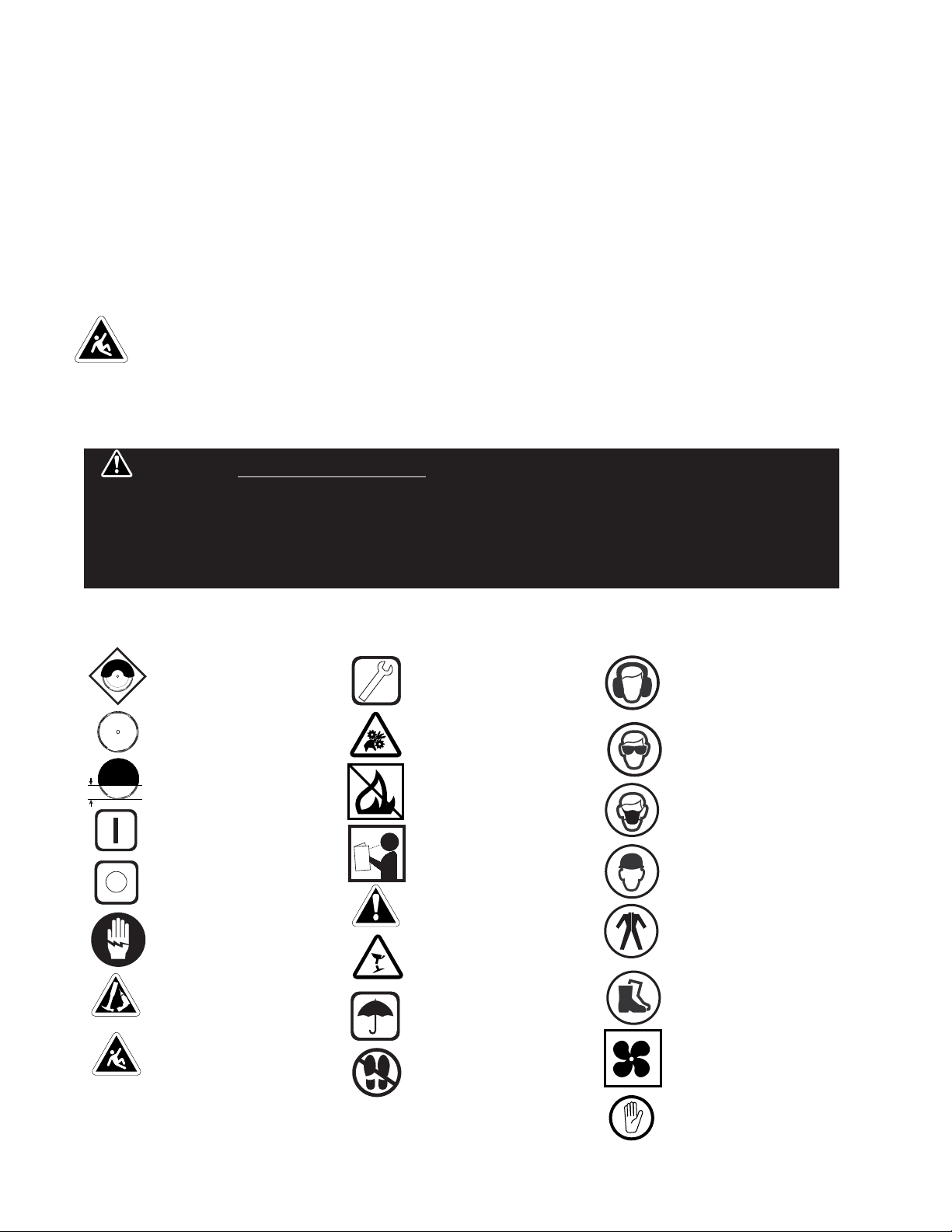
KEEP GUARD IN PLACE
DIAMOND BLADE
BLADE CUTTING DEPTH
ELECTRIC SWITCH O
ELECTRIC SWITCH ON
ELECTRICAL HAZARD
REMOVE TOOLS
PAY EXTREME
ATTENTION
REPAIRS TO BE DONE
MACHINE HAZARD
LAMMABLE
READ INSTRUCTIONS
CARE ULLY
WARNING
RAGILE
KEEP DRY
DO NOT STEP ON
WEAR HEARING
PROTECTION
WEAR EYE PROTECTION
WEAR BREATHING
PROTECTION
WEAR HARD HAT
WEAR PROTECTIVE
CLOTHING
WEAR SA ETY SHOES
WELL VENTILATED
NO NON-WORKING
PERSONNEL
21. Extension cords. Make sure your extension cord is in good condition. When using an extension cord,
be sure to use one heavy enough to carry the current your product will draw. An undersized cord will cause
a drop in line voltage resulting in loss of power and overheating. Extension cord tables (refer t page 12)
show the correct size to use depending on cord length and nameplate ampere rating. If in doubt, use the
next heavier gauge. The smaller the gauge numbers the heavier the cord.
22. Do not abuse cord. Never carry tool by cord or pull it to disconnect from receptacle, Keep cord from
heat, oil, and sharp edges.
23. Guard against electric shock. Prevent body contact with grounded surfaces. or example, pipes,
radiators, ranges and refrigerator enclosures.
24.Outdoor use extension cords. When tool is used outdoors, use only extension cords intended for use
outdoors and so marked.
25. Stay alert. Watch what you are doing. Use common sense. Do not operate tool when you are tired.
26. Drugs, alcohol, medication. Do not operate tool while under the influence of drugs, alcohol or any
medication.
27. Store idle tool. When not in use, tool should be stored in a dry and locked place, out of reach of children.
ii. SYMBOLS
CALIFORNIA PROPOSITION 65: Sawing and drilling generates dust. Ex essive airborne
parti les may ause irritation to eyes, skin and respiratory tra t. To avoid breathing impairment always employ
dust ontrols and prote tion suitable to the material being saw or drilled in a ordan e with OSHA (29 CFR Part
1910.1). Diamond blades improperly used are dangerous. Comply with ANSI Safety Code B7.1 and OSHA
overing speed, safety guards, flanges, mounting pro edures, general operating rules, handling, storage and
general ma hine ondition.
WARNING!

– 5––
iii. FEATURES
CLEAR VIEW AIR FILTER
is easily maintained and
protects the motor
providing a longer life
for the motor
STURDY HANDLES
for easy transport
TABLE LOCKING MECHANISM
facilitates the saw’s chopping
operation
OPTIONAL OUTER TRAY
for wet application
POWERFUL 3 HP (AT PEAK)
Carbon Brush motor cuts large
material in a single pass
The VX141MS Masonry saw is designed for the professional contractor in mind. I enhances performance with a
multitude of features facilitating operation.
REINFORCED
RIGID FRAME
contruction
provides steady
precision cutting
VX141MS MASONRY/BRICK SAW
MOTOR MAX. BLADE
CAPACITY
CUTTING
LENGTH
CUTTING
DEPTH WEIGHT SIZE
i . SPECIFICATIONS
14" blade with
1" (25.4mm)
arbor
16"
Max material
size 8 x 8 x16"
5" 75 lbs.
uncrated
31.5 x 18.5
x 19"
3 HP Peak
115 v, 60 Hz,
3,600 rpm

– 6–
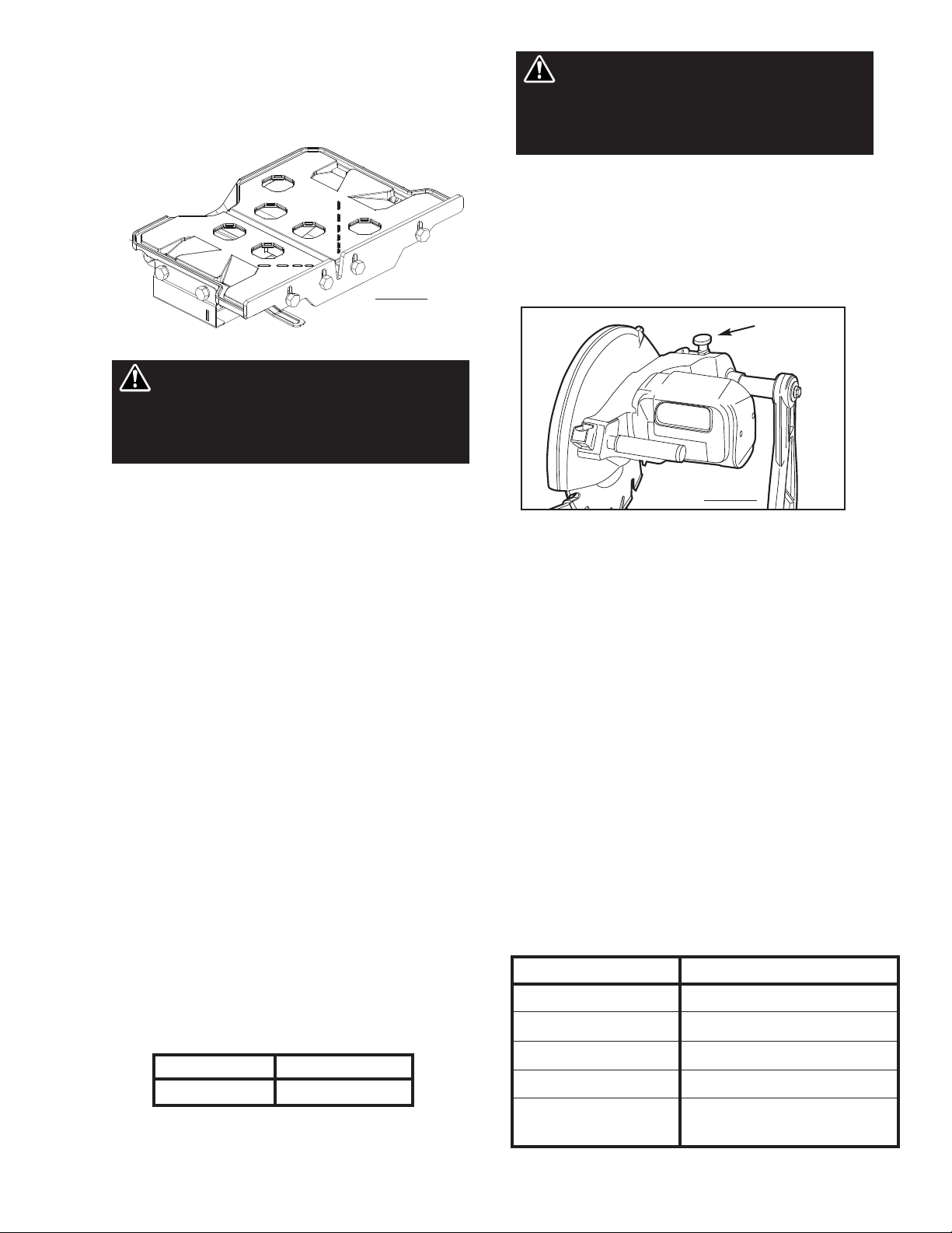
i. INSTALLATION AND OPERATION
1. Move the blade shaft cover upwards. To
remove the blade lock nut, open the shaft
space. Figure 1.
2. Place the 14" blade onto the blade shaft.
Make sure that the directional arrow is
pointing in the direction of the shaft
rotation.
3. Lock the blade lock nut with the outer
flange. Use the multiple wrench provided
to fasten the blade tightly.
To install the cutting table to the machine:
1. Set the cutting table on the rails. Figure 2.
2. Install the screws and brackets to the
cutting table.
3. To remove the cutting table, do the reverse
of the above two steps.
. UNPACKING
Open the container. Carefully lift the saw out evenly by the frame. Be certain you have the following
items before you discard the container:
• Saw • Extra air filter
• 14" saw blade • 45º/90º rip guide
• Universal wrench • Owner’s manual
BLADE INSTALLATION CUTTING TABLE ASSEMBLY
Figure 1
Figure 2
– 7––
THE CUTTING TABLE
The heavy-duty cutting table provides the durability to
handle large materials. Figure 3.
STEPS TO USE THE 45˚ / 90˚ RIP
GUIDE
1. Set the rip guide by positioning it on the
desired dimension and tighten the threaded
knob. Make sure that the rip guide is firmly
tightened to avoid slippage. The rip guide can
be used 90˚ rip cugts and 45˚ angle cuts from
both the left and right side. (Note: The
straight and 45˚ angled slits on the bottom of
the rip guide.)
2. After the rip guide is positioned for the
desired cut, place material flat against the rip
guide and the measurement rail. or the 45˚
rip cuts, place the corner of material in the
open slot of the measurement rail.
3. Simply line up the material being cut with the
appropriate pre-marked lines on the cutting
table.
4. Now you are ready to make your cut.
CUTTING DEPTH
The recommended cutting depth is 1/4" below the
cutting table surface. When setting the cutting depth,
do a practice pass with the table to make sure the
blade does not cut into it.
THE SPRING LOCK PIN
The VX141MS Masonry Saw is designed with three
different cutting heights for jam cutting, a moving
head for chop (or plunge cutting), and a moving cart
combined with the moving head for step cutting to
help make any cutting task easier.
1. Before adjusting the cutting depth always
disconnect the electrical power supply.
2. To adjust the saw’s fixed cutting position, pull
up on the Angle Lock Pin, Figure 4, move the
head to the new position, release the Angle
Lock Pin, and rotate the cutting head
up/down until the Angle Lock Pin lokcs into
position (lowest position for cutting thru
bricks). The middle position is for cutting
block and the upper position for blade
replacement.
CHOP / PLUNGE SAW
OPERATION
To operate the VX141MS as a chop or plunge saw:
pull up on the Angle Lock Pin, rotate 90 degrees, and
release. Now the cutting head can be rotated by
pulling up or pushing down on the cutting head
handle. When not in use, always lock the head into
one of the three cutting height positions.
WAR I G: Only use the 14" diameter blade
for this saw. Setting smaller size of diamond blade
may grab the material being cut, causing damage
and possibly injury.
WAR I G: It is recommended to cut all the
way through the material being cut. Failure to do
so can result in the diamond blade grabbing the
material causing damage and possibly injury.
Figure 3
Blade Diameter Cutting Depth
14" 5 inch
HEAD POSITIO APPLICATIO
ixed Lowest Jam cutting bricks
ixed Middle Jam cutting block
ixed Upper Diamond blade replacement
Moving Chop or Plunge Cutting
Moving head with Step cutting
moving table
Figure 4
Angle
Lock Pin

– 8–
ii. PROPER BLADE USE
DO’S
• Inspect blades daily for cracks or uneven wear.
• Always use appropriate blade for material being cut.
• Inspect arbor shaft for uneven wear before mounting blade.
• Always use blades with the correct arbor shaft size.
• Ensure that blade is mounted in the correct direction.
• Use proper safety equipment when operating the saw.
• Secure the blade to the arbor with a wrench.
• Periodically check the blade for cracks or bond fatigue.
• In addition to the following, always follow wet
recommendations.
• Use appropriate blade for material being cut.
• Inspect segment blades for segment cracking or loss.
• Do not use damaged blades.
• Use proper safety equipment when operating the saw.
DON’TS
• Do not operate the saw without safety guards in position.
• Do not operate the saw with blades larger than 14".
• Do not cut dry with blades marked “Use Wet”.
• Do not exceed manufacturer’s recommended maximum RPM.
• Do not force blade into material. Let blade cut at its own
speed.
• In addition to the following, always follow wet
recommendations.
• Do not make long cuts with dry blades. Allow them
to air cool.
• Do not use the edge or side of blade to cut or grind.
• Do not attempt to cut a radius or curve.
• Do not cut too deep or too fast into the material.
• Do not cut any material not recommended by blade
manufacturer.
iii. CARBON BRUSH REPLACEMENT
The VX141MS Masonry Saw uses a high horsepower low
amperage air cooled brush motor. Replace the carbon
brushes when the motor begins to loose power. Brushes
typically need to be replaced during the life of the saw.
Replace the brushes when over 2/3 of their original length is
used (when the overall length of the brush is less than 7/16”
(11.1 mm). It is normal for the brushes to wear down.
To replace the carbon bursh, perform the following steps:
1. Disconnect the electrical supply.
2. Remove the air filter.
3. Remove the four (4) motor air in-take cover mounting
screws. See Figure 5A.
4. Remove the motor air in-take from the motor.
5. Use a coin or wide blade screw driver to remove the
carbon brush cap. Use care not to damage the carbon
brush cap. Inste the cap for damage. If the cap has any
signs of damage, replace. See Figure 5B.
6. Remove the carbon brush.
7. Use the compressed air to blow any access carbon build
up out of the motor.
8. Inspect the inside of the motor by looking into the brush
holder for any excessive wear or carbon build-up.
9. Place the new carbon brush.
10. Replace the carbon brush cap and tighten the cap with a
coin or wide blade screw driver. Only snug the cap down.
Over tigthening the cap can cause damage to the cap.
11. Reinstall the motor air in-take cover and re-attach the
four mounting screws. Do not over tighten.
12. Clean the air filter.
13. Re-install the air filter.
Figure 5B
Figure 5A

– 9––
x. CARE AND MAINTENANCE
ix. AIR FILTER
CLEANING
A TER EVERY USE O THE MACHINE:
• Remove dirty water from container.
• Remove dirt and mud from the bottom of the
container
A TER WET CLEANING AND BE ORE USING THE
MACHINE AGAIN:
• Connect the machine to an electric power
outlet equipped with a G CI safety power
breaker. If the safety power breaker cuts off
the electrical power supply, do not try to
operate the machine but have it checked by an
authorized dealer first.
BE ORE AND A TER A PROLONGED TIME:
• After not using the machine for a prolonged
period of time, clean and lubricate all movable
parts.
• Check that the saw is sitting properly on the
folding stand.
• Check that all the screw joints and nuts are
fixed.
• Check that the roller table is in its guides and
that is easily moves to and from.
• With the saw blade removed, switch on the
motor for an instant and switch it off again. If
the motor does not run, have the machine
inspected by a qualified electrician.
WAR I G: For your saf ty b for p rforming
any maint nanc on th saw turn off th pow r
switch and unplug th pow r cord.
WAR I G: Using th machin with a dirty,
damag d, or missing air filt r will r sult in motor
damag and is not cov r d und r warranty.
The VX141MS Masonry Saw is equipped with a specially designed air filter to help protect the motor from the damage
due to high speed dust intake during operation.
AIR FILTER REPLACEMENT
To replace the air filter, perform the following steps:
1. Carefully removed the old air filter from the
motor air in-take cover opening. Note: Pull the
air filter thru the opening in the front of the
motor air in-take cover.
2. Inspect the new air filter for damage.
3. Place the new air filter into the motor air in-take
cover.
4. The air filter should fill the opening in the front
of the air in-take cover and should completely fill
the filter cavity.
CLEANING THE AIR FILTER
To clean the air filter, perform the following steps:
1. Carefully removed the old air filter.
2. Clean the air filter by patting, and shaking the
dust from the filter. It also be cleaned with
water. After clean dry before replace the air in-
take. Compressed air can be used to blow the
dust out of the filter.
3. Inspect the filter for damage. Any damaged air
filter must be replaced before using the
machine.
4. Replace the filter into the motor air in-take.
5. Check to see if the air filter is installed properly.
The air filter should fill the opening in the front
of the air in-take cover and should completely fill
the filter cavity.
– 10 –
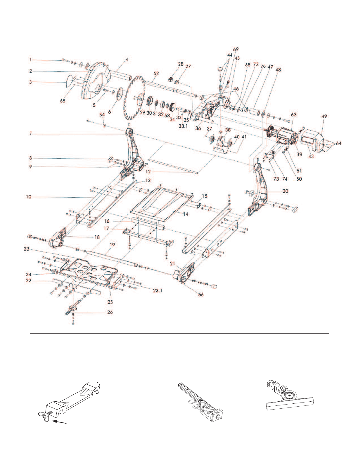
xi. REPLACEMENT PARTS LIST
Knob Only (1)
V35016
ame (Qty.)
Complete 45˚/90˚ Rip Guide with Knob (1)
Part umber
V35000
ame (Qty.)
(Optional) Master Guide (1)
Part umber
V370064
ame (Qty.)
(Optional) Angle Guide (1)
Part umber
V370060
xii. ACCESSORIES & PARTS

– 11 –
1 Screw M10XP1.5X20L V390001
2 Blade Guard V390002
3 Arbor Cover BBM/YBM307 V390003
4 Cross Bar Position Tube (Long) 2 V390004
5 Blade Lock Bolt M10X20 1.25 DIN933 V390005
6 Outer lange V390006
7 Arm rame, Left Side V390007
8 Rubber Cap V390008
9 Bolt & Washer (3 pieces) V390009
10 Side rame (1) V390010
12 Dry Kit Cross Bar V390012
13 Sliding Rail (2) V390013
14 Dust Collecting Pan V390014
15 Cross Tub V390015
16 Metal Pan Bracket V390016
17 Metal Pan rame V390017
18 Left ront Joint V390018
19 Cross Tube V390019
20 Arm rame Right side V390020
21 Right ront Joint V390021
22 Ruler Guide V390022
23 Complete Cutting Table V390023
23.1 Cutting Table Retention Bracket V390023.1
24 U-Shape Roller Wheels (2) V390024
25 Metal Bearing Rollers (2pcs./set) V390025
26 Locking Table Bracket V390026
27 Toggle Switch/ (20A) V390027
28 Toggle Switch Safe Bracket V390028
29 Inner lange V390029
30 Plate Blade Shaft Retaining (qty required=4) V390030
31 Shaft Spacer Outer/ (6305 LLB) V390031
32 Bearing Blade Shaft Outer/ (6305 LLB) V390032
33 Blade Shaft BBM/YMN307 V390033
33.1 Key Woodruf V390033.1
34 Gear Blade shaft V390034
35 Bearing Motor Inner V390035
36 Handle Bar V390036
37 Tension Spring Left Side V390037
38 Cutting Head Angle Main Bracket V390038
39 Complete Motor V390062M
40 Tension Spring Right Side V390040
41 Spring Housing Cover V390041
43 Air ilter V390043
44 Angle Adjustment Lock Pin V390044
45 Cutting Head Casting Only V390045
46 Collar Set Cutting Head V390046
47 Cross Bar Position Tube (Short) 1 V390047
48 Cross Bar Position Bracket V390048
49 Motor Air In-Tank Cover V390049
50 Brush Cap (1) V390050
51 Carbon Brushes (2 pcs./set) V390051
52 Main Cross Bar V390052
53 Shaft Spacer Inner V390053
54 Main Cross Bar Position Stopper V390060
63 Screw M5 x 25L V25155
64 Screw M4 x 16L V25105
65 Screw M5 x 15L V3925058
66 Rubber eet (4) V141029
68 Circuit Breaker V141046
69 Power Cable V141001
72 Circuit Breaker Bracket V141068VX
73 Cable Cover V141126
74 M4 x 8 Countersunk Screw V141127
76 Reset Button Cover VS1000-04.1
PART NAME PART NUMBER PART NAME PART NUMBER
ame
(Optional) Wet Cutting Kit
Includes: Water Tub, Water eed, Drip Tray,
Drain Plug, Water Pump
Part umber
V350MSWKIT
ame (Qty.)
(Optional)
Water Hose Kit (1)
Part umber
V350MSGHKIT
ame (Qty.)
(Optional) Brick Saw Stand (1)
Part umber
V350MS

– 12 –
xiii. ELECTRICAL MOTOR SPECIFICATIONS
Horsepower 3 HP
Volts 115V/230V
Amps 15A
Motor RPM 3,600 rpm
Cycle 60 Hz
Watts 2238
Length of Cord
3 HP - 115 V
25'
50'
75'
Recommendations:
• It is recommended that a 15 amp circuit be used while operating this saw.
This will prevent possible power interruption or loss.
• Always plug saw as close as possible to the power source while operating.
This will allow you to receive optimum electricity.
Electrical Wiring Diagram
WAR I G: To avoid
permanent motor damage you
must use the correct extension
cord. ever use more than one
extension cord at a time. Follow
the chart for proper size.
WIRE
GAUGE
No. 10
No. 8
No. 6
xi . WATER HOSE KIT INSTALLATION
1. Orient the water pipes as shown in ig. A. Insert the
shortest pipe from the "Y" adapter into the adjacent
sleeve at the rear of the blade guard. irst, you will need
to remove the black cap covering the hole insert (#1).
The longest pipe, which has a control valve midway,
should be pointed towards the floor. Secure the "Y"
adapter to the rear of the blade guard using the provided
bracket and screws.
2. Insert the second pipe protruding from the top of
the "Y" adapter into the slot located on the side of
the blade guard towards the front of the saw. This
is the hole in the front of the blade guard (#2), do
not remove the black caps on the side. See ig. B.
#1
#2
Black caps
(do not
remove)
Some force will be required to
pinch the mouth of the pipe
when inserting it into the slot.
Fig. A
Fig. B

– 13 –
x . TROUBLESHOOTING
Problem Possible Cause Solutio
Machine does not run when
switched on.
Power cord not properly
fixed/plugged in.
Check that the machine is properly
connected to the power supply.
Motor stops (power cut out). Too much pressure exerted
while cutting.
Exert less pressure when cutting.
Poor machine performance little
power.
Power cord/extension cable too
long or cable still wound up
inside cable drum.
Use a power cord/extension cable of
the rated length, use a cable drum
with a cable fully extended.
Incorrect specification for saw
blade.
Use a saw blade which corresponds
to the material being cut.
Saw has a defective electric
system.
Have the electric system of the saw
checked by a qualified technician.
Power cord defective. Have the power cord checked,
replaced if necessary.
Main power switch defective. Have the main power switch checked
and replaced if necessary by a
qualified electrician.
Loose electrical connection
inside the electric system.
Have the whole electric system of the
machine checked by a qualified
electrician.
Motor defective. Have the motor checked and replaced
if necessary by a qualified technician.
Power network is insufficient. Observe the electric ratings of the
machine and connect it only to a
power network which complies with
these ratings.
Drive motor no longer runs at
rated speed (r.p.m.).
Have the motor checked by a
qualified electrician and have it
replaced if necessary.
For your safety and the safety of others, turn the power swit h off and always remove the
plug from power sour e before troubleshooting. Repairs performed by unauthorized
personnel ould ause serious hazard. We re ommend that servi e to this tool be performed by a qualified servi e
te hni ian with original equipment repla ement parts.
WARNING!

– 14 –
Problem Possible Cause Solutio
Saw blade wobbles when
running.
Saw blade is damaged or bent.
lange of the saw blade is
damaged.
Shaft of the motor is bent.
Have the saw blade aligned/flattened.
Clean the receiving flange.
Solder the diamond segments of the
old blade onto another saw blade or
use a new blade.
Replace the saw blade flange.
Replace the electric motor.
Diamond segment becomes
loose.
Overheating of the saw blade;
cooling water not sufficient.
Have the diamond segment soldered
on the blade again; ensure optimum
flow of cooling water.
Cracks in or near the diamond
segment.
Saw blade too hard.
ixed flange is worn out.
Motor shaft bearing. Replace the bearing of the motor shaft.
Use a softer blade.
Have the fixed flange replaced.
Saw blade is blunt. Saw blade type is unsuitable for
the material being cut.
Saw blade type is unsuitable for
the machine performance.
Saw blade too hard.
Use appropriate type of saw blade.
Appearance of cut is not optimal. Poor tension in the blade
material.
Return the saw blade to the
manufacturer.
Too much load placed on the
saw blade.
Diamond segments are blunt.
Use a suitable saw blade.
Sharpen the saw blade.
The center hole in the saw blade
has become wider due to wear.
The saw blade has slipped on
the motor shaft when running.
The arbor of the saw blade must be
fitted with an appropriate adapter ring.
Check the receiving flange and have it
replaced if necessary.
Diamond segments are blunt. Sharpen the diamond saw blade.
Irregular run of the saw blade. Poor tension in the blade
material.
Return the saw blade to the
manufacturer.
Excessive wear. Wrong type of saw blade.
Shaft of motor causes wobbling.
Overheating.
Use harder saw blades.
Have bearings of the motor of the
motor replaced.
Ensure optimum flow of cooling
water.
– 15 –
Problem Possible Cause Solutio
Saw blades shows blooming
colors.
Lateral friction when cutting. The material feed is too high; proceed
more slowly.
Grinding marks on the saw
blade.
Material is not being fed parallel
to the saw blade.
Poor tension in the blade material.
Ensure that the direction of feed is
absolutely parallel to the saw blade.
Adjust the roller table/have it adjusted.
Too much load on the saw blade. Have the saw blade tensioned.
The material feed is too high, proceed
more slowly.
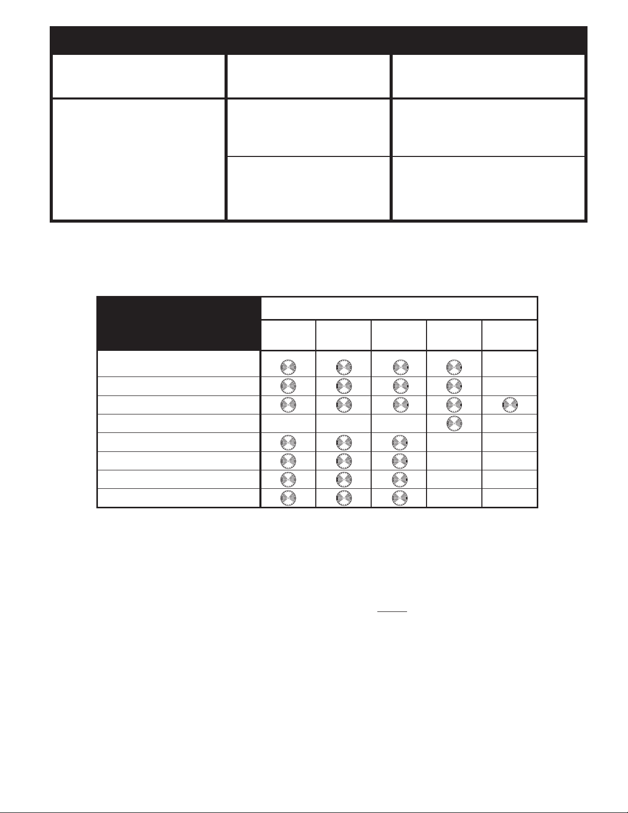
x i. THE RIGHT BLADES DOES THE RIGHT JOB
APPLICATION
PEARL BLADE
SERIES
Reactor ADM™ Concrete/Masonry
P5™ (BB) Masonry
P5™ ( SP) Hard Materials
P2 PRO-V™ (SDS) Hard Materials
P5™ (CSP) Concrete/Masonry
P4™ (CP) Concrete/Masonry
P2 PRO-V™ Concrete/Masonry
P1 EXV™ Concrete/Masonry
brick block paver hard brick refrac ory
brick
x ii. HOW TO ORDER PARTS
Please have the following information ready before calling:
• Serial Number of your Saw • Model Number of the Saw • When purchased and where • Part Description
All parts listed may be ordered from your Local warehouses. If the part is not stocked locally, call our Corporate office and ask for our
Customer Service Department. or Technical Support call 1-800-969-5561. In Canada call 1-800-387-0008. There is a $25.00
minimum order.
Return Policy: Return goods for credit or exchange on the basis of the following terms: (1) They must be current products; (2) Items
returned for replacement or refund should be in original cartons and must be accompanied by a packing slip with the following
information: Returned Goods Authorization (RGA) number obtainable from Customer Service Department • List of items returned •
Reason(s) for return(s) • Copy of original invoice(s); (3) reight charges must be assumed by sender; (4) Returning goods are subject
to a 15% handling charge to cover our cost of repacking and restocking. All Prices are subject to change without notice.
Disclaimer: Pearl Abrasive Co. reserves the right to make changes or improvements on its products without incurring an additional
obligation including any obligation to make corresponding changes or improvements to products previously manufactured or sold.
Pearl reserves the right to discontinue products at any time without notice.
All illustrations displayed in this manual are the property of Pearl Abrasive Co. and shall not be duplicated or reproduced without the
express written consent of Pearl Abrasive Co.
or the most effective cutting and blade life always use the recommended Pearl Abrasive Co. blade.
Part o. VX141MS • 04/18
GEORGIA • USA
3950 STEVE REYNOLDS BLVD.
NORCROSS, GEORGIA 30093
ONTARIO • CANADA
375-2 PIDO ROAD
PETERBOROUGH, ONTARIO K9J-6X7
CORPORATE OFFICE: SO. CALIFOR IA • USA
4900 ZAMBRANO ST., COMMERCE, CA 90040-0031
562-927-5561 • AX 562-928-3857
Toll Free: 800-969-5561
www.pearlabrasive.com
This manual suits for next models
1
Table of contents
Other Pearl Saw manuals

Pearl
Pearl VX141MS User manual

Pearl
Pearl PA7TTR Owner's manual

Pearl
Pearl VX RSPRO R Owner's manual

Pearl
Pearl PA-7 Owner's manual

Pearl
Pearl PA7TT Owner's manual

Pearl
Pearl VX RSPRO VX1048RSPRO Owner's manual

Pearl
Pearl VX141MS User manual

Pearl
Pearl VX5WV Owner's manual

Pearl
Pearl PA-10 User manual

Pearl
Pearl CX10 Owner's manual


