Pearl VX RSPRO R Owner's manual

Caution! Read Safety and General Instructions carefully before using saw for the first time.
Patents Pending
Assembled in U.S.A.
Pearl Abrasive Co. 2.1 RAIL SAW
REV. 3
MODEL VX10RSPROR RAIL SAW
OWNER’S/OPERATOR’S MANUAL
serial number -
You should record the Serial Number of your saw on this
Owner’s/Operator’s Manual and on the Warranty Card.
The Warranty Card must be sent back with all the required
pertinent information for the warranty to take effect.
RENTAL
R

i. TABLE OF CONTENTS
ii. GENERAL SAFETY RULES AND PRECAUTIONS . . . . . . . . . . . . . . . . . . . . . . . . . . . . 3
iii. SILICA DUST WARNING . . . . . . . . . . . . . . . . . . . . . . . . . . . . . . . . . . . . . . . . . . . . . . . 5
iv. FEATURES . . . . . . . . . . . . . . . . . . . . . . . . . . . . . . . . . . . . . . . . . . . . . . . . . . . . . . . . . . 5
v. SPECIFICATIONS . . . . . . . . . . . . . . . . . . . . . . . . . . . . . . . . . . . . . . . . . . . . . . . . . . . . . 6
vi. UNPACKING, ASSEMBLY & SET-UP . . . . . . . . . . . . . . . . . . . . . . . . . . . . . . . . . . . . . . 6
vii. BLADE INSTALLATION . . . . . . . . . . . . . . . . . . . . . . . . . . . . . . . . . . . . . . . . . . . . . . . . . 9
viii. MOTOR CAPACITOR INSTALLATION . . . . . . . . . . . . . . . . . . . . . . . . . . . . . . . . . . . . . 9
ix. SIDE TABLE & SPLASH GUARD INSTALLATION . . . . . . . . . . . . . . . . . . . . . . . . . . . 10
x. WATER PUMP INSTALLATION . . . . . . . . . . . . . . . . . . . . . . . . . . . . . . . . . . . . . . . . . . 10
xi. OVERFLOW PLUG INSTALLATION . . . . . . . . . . . . . . . . . . . . . . . . . . . . . . . . . . . . . . 10
xii. THE ADJUSTABLE ANGLE GUIDE . . . . . . . . . . . . . . . . . . . . . . . . . . . . . . . . . . . . . . 10
xiii. OPERATING THE SAW . . . . . . . . . . . . . . . . . . . . . . . . . . . . . . . . . . . . . . . . . . . . . . . . 11
xiv. GROUNDING INSTRUCTIONS . . . . . . . . . . . . . . . . . . . . . . . . . . . . . . . . . . . . . . . . . . 12
xv. CHOOSING THE RIGHT BLADE . . . . . . . . . . . . . . . . . . . . . . . . . . . . . . . . . . . . . . . . 14
xvi. ELECTRIC MOTOR SPECIFICATIONS. . . . . . . . . . . . . . . . . . . . . . . . . . . . . . . . . . . . 15
xvii. DO’S AND DONT’S FOR BLADES . . . . . . . . . . . . . . . . . . . . . . . . . . . . . . . . . . . . . . . 15
xviii. CARE AND MAINTENANCE . . . . . . . . . . . . . . . . . . . . . . . . . . . . . . . . . . . . . . . . . . . . 16
xix. WATER PUMP MAINTENANCE . . . . . . . . . . . . . . . . . . . . . . . . . . . . . . . . . . . . . . . . . 17
xx. ALIGNMENT INSTRUCTIONS . . . . . . . . . . . . . . . . . . . . . . . . . . . . . . . . . . . . . . . . . . 17
xxi. TROUBLESHOOTING . . . . . . . . . . . . . . . . . . . . . . . . . . . . . . . . . . . . . . . . . . . . . . . . . 19
xxii. HOW TO ORDER PARTS . . . . . . . . . . . . . . . . . . . . . . . . . . . . . . . . . . . . . . . . . . . . . . 20
xxiii. CUSTOMER SERVICE . . . . . . . . . . . . . . . . . . . . . . . . . . . . . . . . . . . . . . . . . . . . . . . . 20
xxiv. REPLACEMENT PARTS LIST . . . . . . . . . . . . . . . . . . . . . . . . . . . . . . . . . . . . . . . . . . . 21
PAGE
– 3 –
ii. GENERAL SAFETY RULES AND PRECAUTIONS
1. Know your power tool - read owner’s/operator’s manual carefully. Learn its applications and limitations as
well as the specific potential hazards unique to this tool.
2. Keep guards in place - and in working order.
3. Ground all tools - if tools are equipped with three prong plug, it should be plugged into a three-hole electrical
receptacle. If an adapter is used to accommodate a two-prong receptacle, the adapter lug must be attached to
a known ground. Never remove the third prong.
4. Remove wrenches - Form a habit of checking to see that adjusting wrenches are removed from tool before
turning it “on”.
5. Keep work area clean. Cluttered areas and benches invite accidents.
6. Do not use in dangerous environment. Do not use power tools in damp or wet locations, or expose them to
rain. Keep work area well lighted. Do not use tool in the presence of flammable liquids or gasses.
7. Keep children and visitors away. All children and visitors should be kept at a safe distance from work area.
8. Make workshop childproof with padlocks, master switches or by removing starter keys.
9. Do not force tool. It will do the job better and be safer at the rate for which it was designed.
10. Use right tool. Do not force tool or attachment to do a job for which it was not designed.
11. Wear proper apparel. Do not wear loose clothing, gloves, neckties, rings, bracelets or other jewelry that
may get caught in moving parts. Non-slip footwear is recommended. Wear protective hair covering to contain
long hair.
12. Always use safety glasses. Wear safety glasses (must comply with ANSI Z87.1) at all times. Everyday
eyeglasses only have impact resistant lenses; they are not safety glasses. Use face or dust mask if cutting
operation is dusty, and ear protectors (plugs or muffs) during extended periods of operation.
13. Do not overreach. Keep proper footing and balance at all times.
14. Maintain tools in top condition. Keep tools sharp and clean for best and safest performance. Follow
instructions for lubricating and changing accessories. Inspect tool cords periodically and if damaged, have
repaired by authorized service facility.
15. Disconnect tools. When not in use, before servicing, and when changing accessories, such as blades, bits,
cutters.
16. Avoid accidental starting. Make sure switch is in “off” position before plugging in power cord.
17. Use recommended accessories only. Consult the owner’s manual for recommended accessories. The use
of improper accessories may cause risk of injury to persons.
18. Never stand on tool. Serious injury could occur if the tool is tipped or if the cutting tool is accidentally
contacted.
19. Check Damaged Parts. Before further use of the tool, a guard or other part that is damaged should be
carefully checked to ensure that it will operate properly and perform it’s intended function. Check for alignment
of moving parts, binding of moving parts, breakage of parts, mounting, and any other conditions that may affect
it’s operation. A guard or part that is damaged should be properly repaired or replaced.
20. Never leave tool running unattended. Turn power “off”. Do not leave tool until it comes to a complete stop.
Read all instructions.
As with all machinery there are certain hazards involved with
operation and use of the machine. The following basic safety precautions should be followed at all times to
reduce the risk of fire, electric shock and serious personal injury to you or others.
Keep these important
operating instructions with this product.
WARNING!

– 4 –
KEEP GUARD IN PLACE
DIAMOND BLADE
BLADE CUTTING DEPTH
ELECTRIC SWITCH OFF
ELECTRIC SWITCH ON
ELECTRICAL HAZARD
REMOVE TOOLS
PAY EXTREME
ATTENTION
REPAIRS TO BE DONE
MACHINE HAZARD
FLAMMABLE
READ INSTRUCTIONS
CAREFULLY
WARNING
FRAGILE
KEEP DRY
DO NOT STEP ON
WEAR HEARING
PROTECTION
WEAR EYE PROTECTION
WEAR BREATHING
PROTECTION
WEAR HARD HAT
WEAR PROTECTIVE
CLOTHING
WEAR SAFETY SHOES
WELL VENTILATED
NO NON-WORKING
PERSONNEL
21. Extension cords. Make sure your extension cord is in good condition. When using an extension cord,
be sure to use one heavy enough to carry the current your product will draw. An undersized cord will cause
a drop in line voltage resulting in loss of power and overheating. If in doubt, use the next heavier gage. The
smaller the gage numbers the heavier the cord.
22. Do not abuse cord. Never carry tool by cord or pull it to disconnect from receptacle, Keep cord from
heat, oil, and sharp edges.
23. Guard against electric shock. Prevent body contact with grounded surfaces. For example, pipes,
radiators, ranges and refrigerator enclosures.
24.Outdoor use extension cords. When tool is used outdoors, use only extension cords intended for use
outdoors and so marked.
25. Stay alert. Watch what you are doing. Use common sense. Do not operate tool when you are tired.
26. Drugs, alcohol, medication. Do not operate tool while under the influence of drugs, alcohol or any
medication.
27. Store idle tool. When not in use, tool should be stored in a dry and locked place, out of reach of children.
CALIFORNIA PROPOSITION 65: Sawing and drilling generates dust. Excessive airborne
particles may cause irritation to eyes, skin and respiratory tract. To avoid breathing impairment always employ
dust controls and protection suitable to the material being saw or drilled in accordance with OSHA (29 CFR Part
1910.1). Diamond blades improperly used are dangerous. Comply with ANSI Safety Code B7.1 and OSHA covering
speed, safety guards, flanges, mounting procedures, general operating rules, handling, storage and general
machine condition.
WARNING!
– 5 –
iv. FEATURES
Position lock
cutting head
Powerful 1-1/2HP
Induction motor
allows for large cuts
Blade capacity of 8-10"
enhances cutting capacity
Side Extension Table
Rubber matted
cutting table
Rubber matted
cutting table
Splash guard
reduces water waste
iii. SILICA DUST WARNING
Grinding/cutting/drilling of tile, masonry, concrete, metal and other materials with silica in their composition may give off
dust or mists containing crystalline silica. Silica is a basic component of sand, quartz, brick clay, granite and numerous
other minerals and rocks. Repeated and/or substantial inhalation of airborne crystalline silica can cause serious or fatal
respiratory diseases, including silicosis. In addition, California and some other authorities have listed respirable
crystalline silica as a substance known to cause cancer. When cutting such materials, always follow respiratory
precautions.
Use appropriate NIOSH-approved respiratory protection where dust hazard may occur. Paper masks or surgical masks
without NIOSH approval number are not recommended because they do little to protect the worker. For more information
about respirator programs, including what respirators have received NIOSH approval as safe and effective, please visit the
NIOSH website at http://www.cdc.gov/niosh/topics/respirators
Observe OSHA regulations for respirator use (29 C.F.R.§1910.134).
Visit http://www.osha.gov for more information.
The Pearl VX10RSPRO is a professional saw for cutting tiles, paving stones, large-sized natural
stones, and similar materials.

– 6 –
UNPACKING
Open the carton box cover by lifting the top portion. Locate the accessory box and check its content for the
following items before discarding any packaging:
• Saw • Pin (2)
• Universal Wrench • Water Pump
• Wheel Assemblies (2) • Owner’s Manual
• Drain Plug • Rear Splash Guard
• Wing Screw • Extension Table
• Knobs (2) • Lifting handles (2)
• Angle guide
Proceed to the following section to complete assembly of the saw.
vi. UNPACKING,ASSEMBLY & SET-UP
v. SPECIFICATIONS
VX10RSPRO RAIL SAW
MOTOR BLADE
CAPACITY
CUTTING
LENGTH
CUTTING
DEPTH WEIGHT
DIMENSIONS*
(legs folded)
8"-10" Blade
5/8" arbor blade
46" rip cut,
32" diagonal
with plunge cut
8": 1-1/2"
10": 2-5/8"
172 lbs. L: 60"
W: 25"
H: 24"
1-1/2 HP
115 v, 60 Hz,
3,450 rpm
Induction motor
*Dimensions do not include extension tables and drip trays.
– 7 –
ASSEMBLY & SET-UP
1. Remove the carton box cover by lifting the upper
cover.
2. Locate the accessory box and open it. Obtain the two
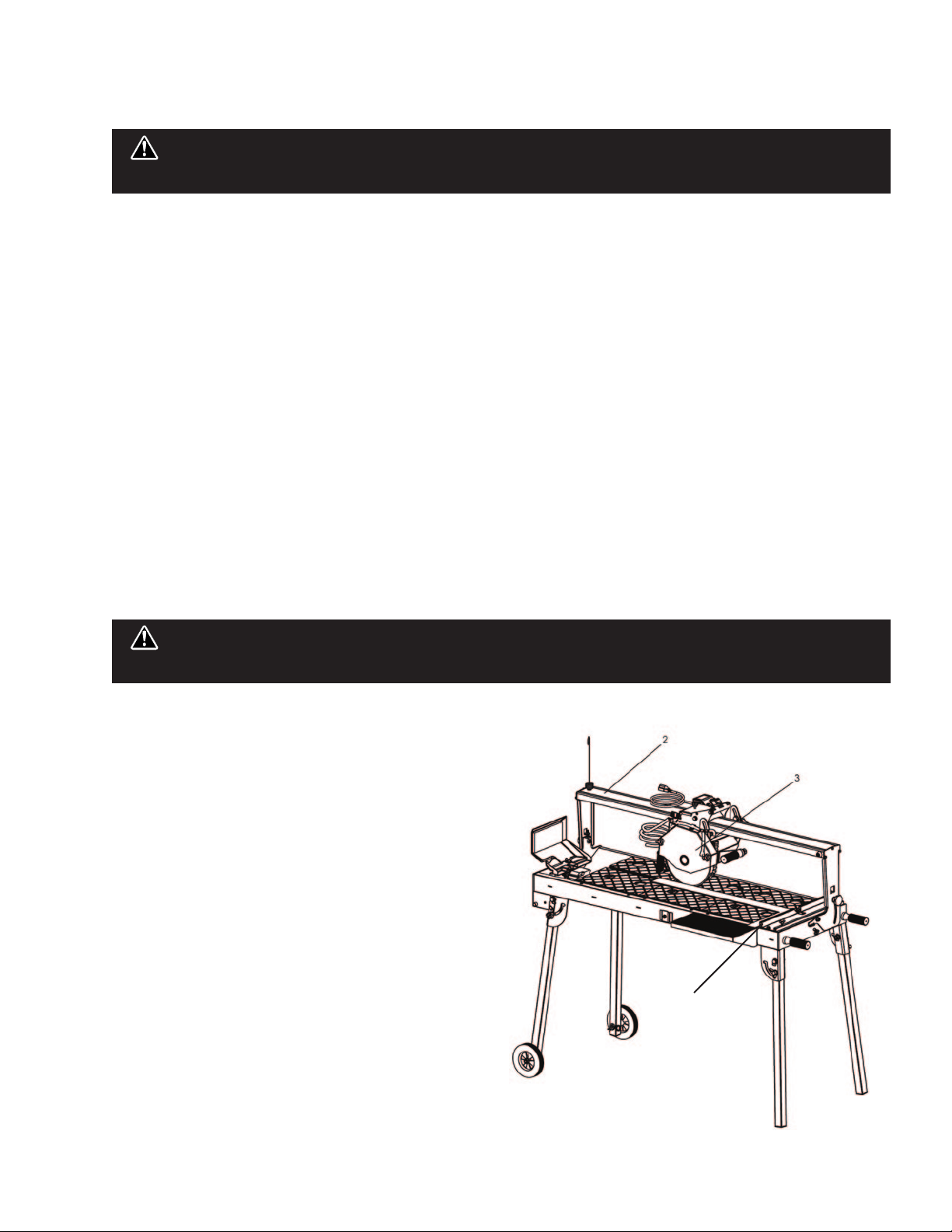
lifting handles and install one on each end of the
saw. Install it in the side furthest from the post.
3. Loosen the lock knob on top of the cutting head.
4. Deploy the stand legs by following the “folded leg
assembly” section.
5. Install the side extension table, side splash guard
and back splash guard.
6. Install the spring holder on top of the sliding rail to
hold the power cable and the water hose.
7. Fill the tray with water before operating the saw.

– 8 –
SAW STAND ASSEMBLY
FOLDING STAND
1. It is recommended that adjusting the
folding leg be done by at least two people.
2. Remove the detachable wheel assembly
and stow it on the frame.
3. Shift the cutting head away from the end
of the frame where the leg is being
adjusted. Tighten the cutting head
carriage knob to hold the head in place.
4. Loosen the knob that is locking the leg in
place.
5. Lift the saw slightly to give the leg room to
rotate into stow/deployed postion.
6. Slide the leg in place and tighten the knob.
7. Repeat steps 2-4 as required to the
remaining legs.
EASY TRANSPORT
1. It is recommended that adjusting the
folding leg be done by at least two people.
2. Remove the detachable wheel assembly
and stow it on the frame.
3. Shift the cutting head away from the end
of the frame where the leg is being
adjusted. Tighten the cutting head
carriage knob to hold the head in place.
4. Loosen the knob that is locking the leg in
place.
5. Lift the saw slightly to give the leg room to
rotate into stow/ deployed postion.
6. Slide the leg in place and tighten the knob.
7. Insert the detachable wheel assembly in
either the frame/leg position depending
on need.
8. Make sure the head is on the side closest
to the wheels before transporting the saw.
Detachable
wheel
assembly Wing screws
(4) to retract
or deploy the
folding legs
Cutting head
carriage knob

– 9 –
Knurled
Nuts
vii. BLADE INSTALLATION
viii. MOTOR CAPACITOR INSTALLATION
Disconnect
the power plug before installing
the blade onto the blade shaft.
WARNING!
Disconnect the
power plug before servicing the motor.
WARNING!
Setting the
blade too low may damage the
cutting table and if set too high,
the blade may grab the material
being cut, causing damage and
possibly injury.
WARNING!
1. Loosen the knobs securing the blade guard and
remove the guard.
2. Loosen the cutting shaft nut (left-hand thread); while
loosening the nut, block the cutting shaft from
turning.
3. Remove the blade clamping flange. Check that the
contact area between the blade holder assembly and
the diamond saw blade is clean.
4. Install the saw blade on the supporting flange. Ensure
the blade rotation arrow matches the clockwise
rotation of the saw blade shaft.
5. Install the blade clamping flange.
6. Re-tighten the cutting shaft nut. Block the cutting
shaft from turning while tightening the nut.
7. Lightly turn the installed saw blade by hand and check
the blade for true running.
8. Mount the blade guard.
1. Locate the aluminum housing on the side of the
motor body.
2. Using a phillip/cross screw driver to remove the two
screws to open the capacitor housing cover.
3. Pull the capacitor out and remove the two wire caps
to disconnect the wires.
4. Replace the old capacitor with the new capacitor and
reattach the wires using the same wire caps.
5. Close the capacitor cover and make sure the rubber
gasket is properly in place so no water can seep into
the housing.

ix. SIDE TABLE & SPLASH
GUARD INSTALLATION
Install the side table and splash guard as shown in
the illustration to the side. Fasten the knobs/screws
respectively to the saw frame.
1. Place the water pump into the bracket at the left
front corner of the water tray, as shown on right.
2. Position the water outlet of the pump so that it lays
horizontally. Connect the water hose from the blade
guard to the water pump.
3. Plug the power cord into the 3-prong receptacle
coming from the power switch housing.
A tube at the rear end of the saw filters the debris from
the water produced during the cutting operation. Debris
settles in the water tray while the water is allowed to
pass through the tube and into the water bucket, where
fresh and filtered water reside.
1. Remove the water level tube from the plastic bag.
2. Insert the thin end of the tube into the rear hole next
to the water pump, as shown in the illustration.
3. Fill the water tray with water.
The Adjustable Angle Guide is
a two-piece assembly
consisting of a base and an
attachment that rotates. This
guide will support cutting
angles between 0°, 22.5°, 30°,
45° and many more. The
attachment has a casted angle
indicator that show what angle
the Angle Guide is currently
set to support.
xi. OVERFLOW PLUG
INSTALLATION
xii. THE ADJUSTABLE
ANGLE GUIDE
Disconnect the pump
before attempting to handle the pump.
Never operate pump without water in
the tray.
WARNING!
x. WATER PUMP
INSTALLATION
Set
Angle
Indicator
– 10 –

xiii. OPERATING THE SAW
1. After you have made yourself familiar with the
components of your saw, the machine has been
properly set up, the water tray is filled with water,
and the electrical connection is established in
accordance with the relevant safety regulations,
you may now begin with the cutting operation.
2. Before you start operation open the water shut-off
valve.
3. During the operation, the user must stand in front
side of the saw pulling on one of the two handles of
the cutting head when cutting. The workpiece must
rest on the work table and should be pressed
tightly against the cutting fence on the table.
4. Always turn off the saw before you leave the
machine unattended.
5. Prevent accidental restarting of the saw by
unplugging the power cable.
CUTTING AT CONSTANT DEPTH
When cutting at constant depth the cutting head must
be pulled against the work piece. The motor should be
turned off when adjusting the cutting depth.
1. Before starting the cut, hold the current depth by
firmly grasping the plunge handle extending from
the blade guard. Set the cutting head at the desired
cutting depth by first loosening the depth control
knob on the side of the cutting head where the
switch box is located.
2. Adjust the head to the blade depth/clearance
desired. Tighten the depth control knob.
3. Put the workpiece securely on the cutting table.
Have it positioned to achieve the desired cut.
4. Turn on the saw and slowly and uniformly pull the
head along the guide rail and across the workpiece.
5. Slowly return the cutting head to the original
starting position and turn off the motor.
PLUNGE CUTS
The handling of long or partial cuts can be made using
the plunge cutting method. In this case, the cutting
head will not be set to a fixed cutting depth/clearance
while performing a cut. The cutting head is freely
movable during seesaw cutting operations.
1. Before starting the cut, the cutting head must be
fully raised. Be sure to grasp the plunge handle
extending from the blade guard. Loosen the depth
control knob on the side of the cutting head where
the switch box is located.
2. Set the workpiece securely on the cutting table.
Have it positioned to achieve the desired cut.
3. With the head fully raised, move to the desired start
of cut along the path of the blade. Plunge the head
and pull until the desired cut is complete.
4. Slowly return the cutting head to the original
starting position and turn off the motor.
THE CUTTING TABLE
FEATURES:
• The easily removable cutting table is covered with
an anti-skid rubber coating, which allows the
material being cut to sit on the table while the
cutting head is pulled through it.
• Simply line up the material being cut with the
appropriate pre-marked lines on the cutting table.
STEPS TO MAKE MITER CUTS:
1. The bench saw is equipped with a hinged guide rail
that allows the user to make accurate miter cuts.
2. To pivot the guide rail, lightly loosen the knobs at
both ends of the saw.
3. Set the rail to the desired angle by using both hands
to firmly hold the rail and rotating it. While still
holding the rail at the desired angle, tighten each
knob.
Turn off the saw before
pivoting the guide rail. Do not attempt to
pivot the rail mid-cut. The saw blade must be
clear of the material being cut and the saw
must be turned off first!
WARNING!
– 11 –

– 12 –
CUTTING DEPTH
The recommended cutting depth is 1/4" below the
cutting table surface. The cutting clearance has been
fixed from original design.
BLADE DIAMETER CUTTING DEPTH
8 inch 1-1/2 inch
10 inch 2-5/8 inch
Setting the blade too low
may damage the cutting table and if set too high,
the blade may grab the material being cut, causing
damage and possibly injury.
WARNING!
1. Always use the included GFCI plug.
2. In the event of a malfunction or breakdown,
grounding provides a path of least resistance for
electric current, reducing the risk of electric shock.
This tool is equipped with an electric cord which
has an equipment-grounding conductor and a
grounding plug. The plug must be plugged into a
matching outlet that is properly installed and
grounded in accordance with all local codes and
ordinances.
3. Do not modify the plug provided – it is intended to
be used with the included GFCI plug and extension
cord. If using an adaptor for a 2-prong outlet,
always attach the adaptor to the GFCI plug, never to
the power cord.
4. Improper connection of the equipment-grounding
conductor can result in a risk of electric shock.
5. Check with a qualified electrician or service person
if you do not completely understand the grounding
instructions or are unsure that the tool is properly
grounded.
6. If an additional extension cord is needed, attach it
to the 3-prong GFCI plug. Never use an extension
cord longer than 50 feet.
Always repair or replace a damaged or worn cord
immediately.
7. This saw is intended for use on a circuit that has an
outlet that looks like the one illustrated in
Figure 2
.
The GFCI plug used on the saw has a grounding
plug that looks like the plug illustrated in
Figure
2(A)
. A temporary adaptor, which looks like the
adaptor illustrated in
Figures 2(B)
and
2(C)
, may be
used to connect the GFCI plug to a 2-pole
receptacle, as shown in
Figure 2(B)
, if a properly
grounded outlet is not available. The temporary
adaptor should be used only until a properly
grounded outlet can be installed by a qualified
electrician. The green-colored rigid ear, lug, etc.,
extending from the adaptor must be connected to a
permanent ground, such as a properly grounded
outlet box.
Figure 2
(A) (B) (C)
GFCI
plug
Grounding pin
Cover of
grounded
outlet box
Metal
Screw
Grounding
Means
(Lug)
Grounding pin
xiv. GROUNDING INSTRUCTIONS
NOTE -
Use of a Temporary Adapter is not permitted
in Canada.

– 13 –
8. Position of the Tile Saw.
• To avoid the possibility of the appliance plug
or receptacle getting wet, position the tile saw
to one side of a wall-mounted receptacle to
prevent water from dripping onto the
receptacle or plug. The user should arrange a
“drip loop” in the cord connecting the saw to
a receptacle. The “drip loop” is that part of
the cord below the level of the receptacle, or
the connector (if an extension cord is used); it
prevents water from traveling along the cord
and coming into contact with the receptacle.
See Figure 3
.
• If the plug or receptacle does get wet, do not
unplug the cord. Disconnect the fuse or
circuit breaker that supplies power to the
receptacle. Then unplug and examine for the
presence of water in the receptacle.
• If the receptacle is wet, dry it and make certain
that the GFCI Plug is reset before plugging it
back into the receptacle. Do not reconnect
the fuse or circuit breaker until the receptacle
is dry.
9. Extension Cords
• Always use the extension cord included with the
saw.
• If an additional extension cord is needed, use
only a cord that is intended for outdoor use.
These extension cords are identified by the
marking “Acceptable for use with outdoor
appliances; store indoors while not in use.” Use
only extension cords with an electrical rating
higher than the rating of the tool. Refer to the
chart on page 14. Do not use damaged
extension cords. Examine an extension cord
before use and replace it if it is damaged. Do not
abuse extension cords and do not pull on any
cord to disconnect it. Keep the cord away from
heat and sharp edges. Always disconnect the
extension cord from the receptacle before
disconnecting the saw from the extension cord.
• Never use an additional extension cord that is
longer than 50 feet.
10. Always use the Ground Fault Circuit Interrupter
(GFCI) plug included with the saw.
11. The tile saw cord includes a 15-amp twist lock
plug. Do not modify this plug or use an adaptor
on it. This plug is intended to be used with the
GFCI Plug included with the saw. The GFCI has a
standard 3-prong plug that can be plugged into a
standard 3-prong outlet or extension cord.
To reduce the risk of electrocution, keep
all connections dry and off the ground.
Do not touch plug with wet hands.
TOOL
Figure 3
Drip Loop
Supporting
Surface
Power Cord
Drip Loop
GFCI/Power Cord
Connection
GFCI plug
xv. CHOOSING THE RIGHT BLADE
THE RIGHT BLADE DOES THE RIGHT JOB
For the most effective cutting and blade life always use the recommended Pearl Abrasive Co. blade.
APPLICATION
PEARL
BLADE
SERIES
Reactor ADM
HPXL Series
HP Series
Turbo Mesh
DTLB19 Series
Pro-V Series
Glass Blade
SH Series
CERAMIC EXTRA HARD PORCELAIN MARBLE GRANITE HARDSTONE GLASS TILE MOSAIC
TILE CERAMIC METAL TILES
– 14 –
• The blade shaft speed of this saw is exclusively designed for cutting with
diamond saw blades. The saw may only be used for cutting natural and
artificial stone materials, do not cut wood or metal!
• The saw uses diamond saw blades with diameters up to 10". Saw blades
with larger diameters must not be installed on the saw.
• Choose the correct type of saw blade for the material to be cut and the
required cutting depth.

WET CUT BLADES
DO’S
•Inspect blades daily for cracks or uneven wear.
•Always use appropriate blade for material being cut.
•Inspect arbor shaft for uneven wear before mounting
blade.
•Always use blades with the correct arbor shaft size.
•Ensure that blade is mounted in the correct direction.
•Secure the blade to the arbor with a wrench.
•Use proper safety equipment when operating the saw.
•Periodically check the blade for cracks or bond fatigue.
•Always have a continuous flow of water on both sides of blade.
DONT’S
•Do not operate the saw without safety guards in position.
•Do not operate the saw with blades larger than 10".
•Do not cut dry with blades marked "Use Wet".
•Do not exceed manufacturer's recommended maximum RPM.
•Do not force blade into material let blade cut at its own speed.
DRY CUT BLADES
DO’S
•In addition to the following, always follow wet
recommendations.
•Use appropriate blade for material being cut.
•Inspect segment blades for segment cracking or loss.
•Do not use damaged blades.
•Use proper safety equipment when operating the saw.
DONT’S
•In addition to the following, always follow wet
recommendations.
•Do not make long cuts with dry blades--allow them to air cool.
•Do not use the edge or side of blade to cut or grind.
•Do not attempt to cut a radius or curve.
•Do not cut too deep or too fast into the material.
•Do not cut any material not recommended by blade
manufacturer.
xvii. DO’S AND DONT’S FOR BLADES
xvi. ELECTRICAL MOTOR SPECIFICATIONS
Horse Power 1-1/2 hp
Volts 115 V/ 60hz
Amps 15 amps
Motor RPM 3,450 rpm
Cycle 60
Phase 1
WIRE
GAUGE
No. 12
No. 10
No. 8
LENGTH OF CORD
25'
50'
75'
Recommendations:
• It is recommended that a 20 amp circuit be used while operating this saw.
This will prevent possible power interruption or loss.
• Always plug saw as close as possible to the power source while operating.
This will allow you to receive optimum electricity.
Electrical Wiring Diagram
WARNING: To avoid
permanent motor damage you
must use the correct extension
cord. Never use more than one
extension cord at a time. Follow
the chart for proper size.
– 15 –

xviii. CARE AND MAINTENANCE
GENERAL RULES
• Always clean the machine before maintenance/ repair.
• Before cleaning/maintenance/repair, the machine must
be switched off with the main power key.
STEPS TO FOLLOW WHEN CLEANING
1. Please do not use aggressive cleaners (i.e. containing
solvents). Do not use high-pressure water jets,
aggressive detergents or solutions and liquids with a
temperature exceeding 86°F Use a fluff-free cloth only.
2. Use a cloth which may be lightly moistened only for
removing dust and dirt. Hard packed dirt can be
removed with a soft brush.
3. For the sake of safety, no water/cleaning liquid/vapor
may penetrate into the electric motor, connectors
/plugs, switches, etc. Therefore cover all apertures,
holes in the housing, connectors or plugs, etc. or seal
them with adhesive tape.
4. Use a soft, low-pressure water jet and a brush to rinse
dirt and incrustations away. Be particularly careful
when near hazardous parts of the machine (e.g.
switch, motor). Clean the motor and switches only by
wiping with a moist cloth.
5. Do not "rinse" the bearings of the drive elements to
prevent them from running dry. The ball bearings of
the machine are permanently lubricated.
6. After cleaning, remove all covers and adhesive tape All
screws/nuts which you may have loosened must be
tightened again.
7. After wet cleaning, plug the machine to a power outlet
which is equipped with a ground fault current
interrupt. If the device cuts power, the machine must
be inspected by an authorized dealer prior to use!
AFTER EVERY USE OF THE SAW:
• Remove dirty water from container.
• Remove dirt and mud from the bottom of the
container.
• Rinse the immersion pump with fresh water to prevent
water pump clogging from residual dirt.
AFTER WET CLEANING AND BEFORE
USING THE SAW AGAIN:
• Connect the machine to an electric power outlet
equipped with a "GFCI” safety power breaker. If the
safety power breaker cuts off the electrical power
supply, do not try to operate the machine but have it
checked by an authorized dealer first.
BEFORE & AFTER A
PROLONGED TIME
BEFORE NOT USING THE MACHINE FOR A
PROLONGED PERIOD OF TIME:
• Clean and lubricate all movable parts. DO NOT
GREASE THE GUIDE RAILS.
AFTER NOT USING THE MACHINE FOR A
PROLONGED PERIOD OF TIME:
• Check that the legs are safely fixed.
• Check that all screw joints and nuts are fixed.
• Check that the roller table is rolling on the rails and
that it moves securely back and forth. With the saw
blade removed, switch on the motor for an instant and
switch it off again. If the motor does not run, have the
machine inspected by a qualified electrician.
• Check that the immersion pump works properly. Turn
on the valve if applicable and switch the machine on.
If the pump does not give any water or only a little,
switch the machine
TEMPERATURE CHANGES
AMBIENT TEMPERATURE BELOW 37 F (WINTER)
To prevent the water in the pump and cooling system from
freezing, remove the water after using the machine or
when there will be a long break. Make sure that the cooling
system is entirely drained so that there is no water left
inside the pump, the bearing house and the water hose.
For your safety before performing any maintenance on the saw, turn off the power switch and
unplug the power cord.
WARNING!
– 16 –
When the machine has not been used for a long period
of time, hard packed dirt may begin to build up inside
the pump and block the pump wheel. If the machine
is activated with the immersion pump blocked, the
electric motor of the pump will be damaged within a
few minutes. Please follow the steps listed below to
clean the pump before operating the saw.
1. Unscrew the pump filter.
2. Remove the water pump from the water tray/
container.
3. Clean the water pump exterior.
4. Clean the interior where the fan is by removing the
fan cover. If gasket is installed, be careful not to
damage it.
5. The fan can be removed by using pliers to pull it
off. Careful not to damage the fan or the motor
shaft. With it removed, the entire volute can be
cleaned easily.
6. Spin the pump shaft by hand. It should rotate
almost effortlessly. Then press the cleaned fan
back onto the blade. Note to align the shaft
geometry with that of the blade bore before
pressing it back on. Do not press the fan too far
down the shaft or it may not rotate. Spin the fan
blade by hand to confirmit can spin effortlessly.
7. Reassemble the fan cover.
8. Plug the water pump in briefly to check whether it
works properly.
For your safety before performing any maintenance on the saw, turn off the power switch and
unplug the power cord.
WARNING!
For your safety before performing any maintenance on the saw, turn off the power switch and
unplug the power cord.
WARNING!
xix.WATER PUMP MAINTENANCE
REMINDER:
There are 3 methods to adjust the alignment:
1. Cutting fence.
2. Bridge.
3. Cutting head
Note: Usually adjustment method 1 and 2 are the
most common.
METHOD 1: CUTTING FENCE
1. Loosen the bolts that secure the cutting fence.
2. Using a steel square, as shown in Fig. 1, align the
square's long arm with the blade. Both the front
and the rear end of the blade's rim should have
contact.
3. Adjust the cutting fence such that the fence face
sits flush with the steel square's short arm.
4. Now move the cutting head back and forth, along
the bridge, to check for consistent blade contact
with the steel square. Make sure the short arm
does not move during this process. Interference
from the blade may move the steel square away
from the cutting fence.
xx.ALIGNMENT INSTRUCTIONS
Fig.1 3D View
1
– 17 –
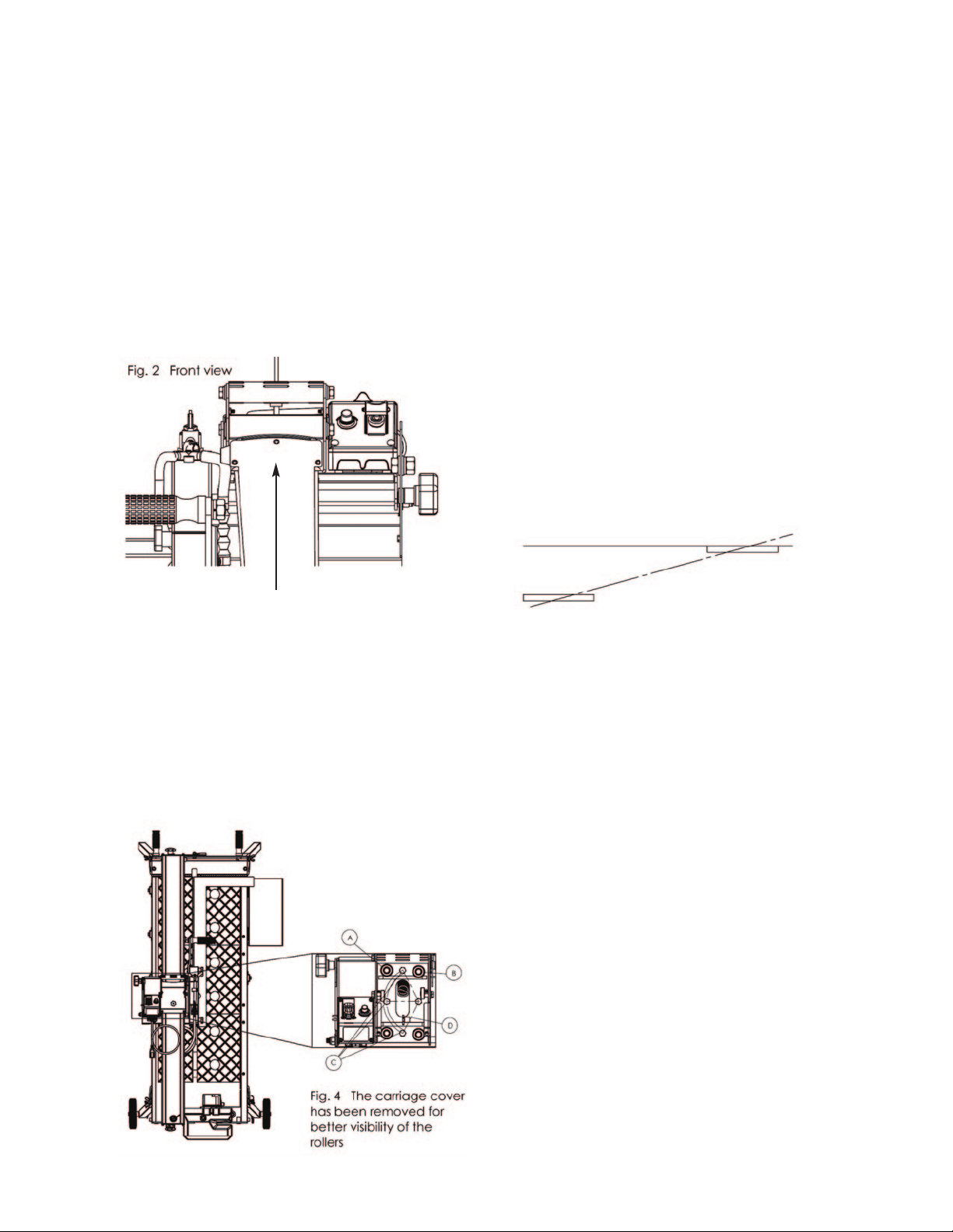
METHOD 2: BRIDGE
1. Loosen the bolts that secure the bridge (Fig. 2).
DO NOT REMOVE THE BOLTS AS THE BRIDGE
AND CUTTING HEAD WILL FALL.
2. Repeat steps listed in method 1 to align the fence.
3. Now if the cutting fence does not move enough to
align the cutting head, the bridge may be shifted
as shown in the illustration below.
Adjustment range of the bridge/rail
METHOD 3: CUTTING HEAD
1. Underneath the carriage cover is four bolts (size
13 wrench) that hold the head's two sub-
assembly together. The upper assembly is the
carriage and the lower assembly is the actual
cutting head. The three bolts highlighted by the
balloon "C", in the illustration below are the actual
bolts that need to be loosened. Only loosen the
bolts enough that the lower sub-assembly can
move, changing the blade shaft's orientation. The
fourth bolt is the pivoting bolt and does not have
to be loosened.
2. If the blade is constantly shifting left, using Fig. 4
as reference, the cutting head must be rotated
counterclockwise (left).
3. If the blade is constantly shifting right, using Fig.
4 as reference, the cutting head must be rotated
clockwise (right). Note: The cutting head should
glide effortlessly across the bridge. Should the
head be too tight or too loose, adjust the rollers on
the left (A) using a size 17 wrench to rotate it.
Rollers on the right (B) are fixed so they cannot be
adjusted.
Fig. 5 depicts how aligning the blade with the steel
square does not always mean the head is aligned with
the bridge.
1. The solid line represents the steel square.
2. The dotted line represents the bridge and ACTUAL
travel direction of the cutting head.
3. The rectangular box represents the blade/cutting
head orientation. As the user pushes/pulls the
cutting head if the cutting head is not properly
aligned with the bridge, the blade will always
moves away from the steel square.
xx.ALIGNMENT INSTRUCTIONS (cont.)
The post holes allow movement of the bridge
+/- 0.5mm in either the left or right direction.
Fig.3
Top
View
Fig.5 Blade
Shifting
– 18 –

xxi.TROUBLESHOOTING
PROBLEM POSSIBLE CAUSE SOLUTION
-Power cord not properly
fixed/plugged in.
-Power cord defective.
-Main power switch
defective.
-Loose electrical connection inside
the electric system.
-Motor defective.
-Too much pressure exerted while
cutting.
-Incorrect specification for saw
blade.
-Saw has a defective electric system.
-Power cord/extension cable too
long or cable still wound up inside
cable drum.
-Power network is insufficient.
-Drive motor no longer runs at rated
speed (r.p.m.).
- The pump draws air.
-Filter clogged.
-Pump wheel of the immersion
pump blocked by dirt.
-Poor tension in the blade material.
-Saw blade is damaged or bent.
-Flange of the saw blade is
damaged. Shaft of the motor bent.
-Overheating of the saw blade;
cooling water not sufficient.
-Check that the machine is properly
connected to the power supply.
-Have the power cord checked,
replace if necessary.
-Have the main power switch
checked and replace if necessary by
a qualified electrician.
-Have the whole electric system of
the machine checked by a qualified
electrician.
-Have the motor checked and
replaced if necessary by a qualified
technician.
-Exert less pressure when cutting.
-Use a saw blade which corresponds
to the material being cut.
-Have the electric system of the saw
checked by a qualified technician.
-Use a power cord/extension cable
of the rated length, use a cable
drum with cable fully extended.
-Observe the electrical ratings of the
machine and connect it only to a
power network which complies with
these ratings.
-Have the motor checked by a
quilified electrician and have it
replaced if necessary.
-Fill the container with water.
-Clean the filter of the pump.
-Disassemble the immersion pump
and clean.
- Return the saw blade to the
manufacturer.
-Have the saw blade aligned/
flattened.
-Clean the receiving flange.
-Solder the diamond segments of
the old blade onto another saw
blade or use a new blade.
-Replace the saw blade flange.
-Replace the electric motor.
-Have the diamond segment
soldered on the blade again; ensure
optimum flow of cooling water.
MACHINE DOES NOT RUN WHEN
SWITCHED ON
MOTOR STOPS
(POWER CUT OUT)
POOR MACHINE PERFORMANCE
LITTLE POWER
INSUFFICIENT FLOW OF COOLING
WATER OR NO COOLING WATER
AT ALL
IRREGULAR RUN OF THE
SAW BLADE
SAW BLADE WOBBLES WHEN
RUNNING
DIAMOND SEGMENT BECOMES
LOOSE
– 19 –

– 20 –
PROBLEM POSSIBLE CAUSE SOLUTION
-Wrong type of saw blade.
- Shaft of motor causes wobbling.
- Overheating.
- Saw blade type is unsuitable for the
material being cut.
-Saw blade ype is unsuitable for the
machine performance.
-Saw blade too hard.
-Diamond segments are blunt.
-Poor tension in the blade material.
-Too much load placed on the saw
blade.
-Diamond segments are blunt.
-The saw blade has slipped on the
motor shaft when running.
-Saw blade overheating due to a lack of
cooling water.
-Lateral friction when cutting.
-Material is not being fed parallel to the
saw blade
-Poor tension in the blade material.
-Too much load on the saw blade.
-Use harder saw blades.
-Have bearings of the motor or the motor
replaced.
- Ensure optimum flow of cooling water.
- Use appropriate type of saw blade.
-Sharpen the diamond saw blade.
-Return the saw blade to the manufacturer.
-Use a suitable saw blade.
-Sharpen the saw blade.
-The arbor of the saw blade must be fitted
with an appropriate adator ring.
-Check the receiving flange and have it
replaced if necessary.
-Ensure an optimum flow of cooling water.
-The material feed is too high; proceed
more slowly.
-Ensure that the direction of feed is
absolutely parallel to the saw blade.
-Adjust the roller table or have it adjusted.
-Have the saw blade tensioned.
-The material feed is too high, proceed
more slowly.
EXCESSIVE WEAR
SAW BLADE IS BLUNT
APPEARANCE OF CUT IS
NOT OPTIMAL
THE CENTER HOLE IN THE SAW
BLADE HAS BECOME WIDER DUE TO
WEAR
SAW BLADE SHOWS BLOOMING
COLORS
GRINDING MARKS ON THE
SAW BLADE
xxii. HOW TO ORDER PARTS
Please have the following information ready before calling: Model Number of the Tile Saw and Part Description
For warranty purpose, please have the following ready: Serial Number and When purchased and where
All parts listed may be ordered from your Local warehouses. If the part is not stocked locally, call our Corporate office and ask for
our Customer Service Department. For Technical Support call 1-800-969-5561. In Canada, call 1-800-387-0008. There is a $25.00
minimum order.
Return Policy: Return goods for credit or exchange on the basis of the following terms: (1) They must be current products;
(2) Items returned for replacement or refund should be in original cartons and must be accompanied by a packing slip with the
following information: Returned Goods Authorization (RGA) number obtainable from Customer Service Department • List of items
returned • Reason(s) for return(s) • Copy of original invoice(s); (3) Freight charges must be assumed by sender; (4) Returning goods
are subject to a 15% handling charge to cover our cost of repacking and restocking. All Prices are subject to change without notice.
Disclaimer: Pearl Abrasive Co. reserves the right to make changes or improvements on its products without incurring an additional
obligation including any obligation to make corresponding changes or improvements to products previously manufactured or sold.
Pearl reserves the right to discontinue products at any time without notice.
All illustrations displayed in this manual are the property of Pearl Abrasive Co. and shall not be duplicated or reproduced without the
express written consent of Pearl Abrasive Co.
xxiii. CUSTOMER SERVICE
AFTER SALE SERVICE
All customer service (technical questions, re-order of parts, etc.) will be provided by our company. All spare parts for after sales
service will be stocked and shipped from our warehouse. If requested, we may arrange for our sales representatives to hold a training
class for product knowledge at dealer’s location.
This manual suits for next models
1
Table of contents
Other Pearl Saw manuals

Pearl
Pearl PA7TTR Owner's manual

Pearl
Pearl PA7TT Owner's manual

Pearl
Pearl VX10RSPRO Owner's manual

Pearl
Pearl VX141MS User manual

Pearl
Pearl VX10.2XLPROR Owner's manual

Pearl
Pearl PA-7 Owner's manual

Pearl
Pearl VX RSPRO VX1048RSPRO Owner's manual

Pearl
Pearl PA-10 User manual

Pearl
Pearl VX5WV Owner's manual

Pearl
Pearl VX141MSD Owner's manual


