Pedigo P-2010-S User manual

OPERATION & CARE
MANUAL
OPERATION & CARE
MM-1070 • 05/21
PRINTED I N U.S.A.
BLANKET WARMING CABINET
P-2010-S
120V
P-2010-S

INDEX
Transport and Storage .......................... 1
Delivery .................................... 1
Unpacking .................................. 1
Safety Procedures and Precautions ................. 2
Installation
Preparation ............................... 3
Electrical Information........................ 3
General Warnings .........................4-5
General Information ......................... 6
Dimension Drawings, weights & capacities ........ 7
Operating Instructions
Blanket Chamber Operational Procedures ......... 8
Care and Cleaning
Cleaning and Preventative Maintenance .......... 9
Protecting Stainless Steel Surfaces ............... 9
Cleaning Agents ............................ 9
Cleaning Materials .......................... 9
Care and Cleaning ..........................10
Clean the Unit Regularly......................10
Troubleshooting Guide ........................11
Service Parts Lists and Drawings .............12-13
Wire Diagrams (always refer to wire diagram under top cover of unit
for most current version)
Warranty
Transportation Damage and Claims.......Back Cover
Limited Warranty....................Back Cover
Pedigo Products, Inc. • 4000 S.E. Columbia Way • Vancouver, WA 98661 l U.S.A.
Phone: 800.822.3501 • Fax: 360.696.1700 • www.pedigo-usa.com

UNPACKING AND SET-UP
Transport and Storage Environmental Conditions (not to exceed 15 days)
• Ambient temperature range of -40 to +159°F (-40° to +70°C)
• Relative humidity range of 10% to 100%, including condensation
• Atmospheric pressure range of 50KPa to 106KPa
DELIVERY
The Pedigo Blanket Warming Cabinet has been
thoroughly tested and inspected to insure only the
highest quality unit is provided. Upon receipt,
check for any possible shipping damage and report it
at once to the delivering carrier. See Transportation
Damage and Claims section located in this manual.
This appliance, complete with unattached items
and accessories, may have been delivered in one or
more packages. Check to ensure that all standard
items and options have been received with each
model as ordered.
Save all the information and instructions
packed with the appliance. Complete and return
the warranty card to the factory as soon as possible
to assure prompt service in the event of a warranty
parts and labor claim.
This manual must be read and understood by
all people using or installing the equipment model.
Contact the Pedigo service department if you have
any questions concerning installation, operation,
or maintenance.
NOTE: All claims for warranty must include the
full model number and serial number of
the unit.
UNPACKING
1. Carefully remove the
appliance from the
carton or crate.
NOTE: Do not discard the
carton and other
packaging material
until you have
inspected the unit
for hidden damage
and tested it for
proper operation.
2. Read all instructions in this manual carefully before
initiating the installation of this appliance.
DO NOT DISCARD THIS MANUAL.
This manual is considered to be part of the
appliance and is to be provided to the owner
or manager of the business or to the person
responsible for training operators. Additional
manuals are available from the Pedigo
service department.
3. Remove all protective plastic film, packaging
materials, and accessories from the appliance
before connecting electrical power.
TRANSPORT AND STORAGETRANSPORT AND STORAGE
1
BLANKET WARMING CABINET

Knowledge of proper procedures is essential to the
safe operation of electrically energized equipment. In
accordance with generally accepted product safety labeling
guidelines for potential hazards, the following signal words
and symbols may be used throughout this manual.
Used to indicate the presence
of a hazard that will cause
severe personal injury, death,
or substantial property
damage if the warning
included with this symbol
is ignored.
Used to indicate the presence
of a hazard that can cause
personal injury, possible
death, or major property
damage if the warning
included with this symbol
is ignored.
Used to indicate the presence
of a hazard that can or will
cause minor or moderate
personal injury or property
damage if the warning
included with this symbol
is ignored.
Used to indicate the presence
of a hazard that can or will
cause minor personal injury,
property damage, or a
potential unsafe practice if the
warning included with this
symbol is ignored.
Used to notify personnel of
installation, operation, or
maintenance information that is
important but not hazard related.
1. Pedigo blanket warmers are intended for warming
cotton blankets ONLY. No other use for this device is
authorized or recommended.
2. This device is intended for use in commercial
establishments where all operators are familiar with
the purpose, limitations, and associated hazards of this
device. Operating instructions and warnings must be
read and understood by all operators and users.
3. Any troubleshooting guides, component views, and
parts lists included in this manual are for general
reference only and are intended for use by qualified
technical personnel.
4. This manual should be considered a permanent part of
this device. This manual and all supplied instructions,
diagrams, schematics, parts lists, notices, and labels
must remain with the device if the item is sold or moved
to another location.
NOTE:
SAFETY PROCEDURES AND PRECAUTIONS
2
NOTE
For equipment delivered for use
in any location regulated by the
following directive:
DO NOT DISPOSE OF ELECTRICAL
OR ELECTRONIC EQUIPMENT WITH
OTHER MUNICIPAL WASTE.
NOTE
Pedigo warmers should not be left
unattended for periods of more than 24 hours.
In case of absences longer than 24 hours,
disconnect the warmer from its power source.

3
Hazardous
Voltage Present
POWER REQUIREMENTS - P-2010-S
120 V.A.C. — 60 Hz, 1 ph
500 Watts, 4.1 Amps
Safety Class I Equipment
No Applied Parts
NEMA 5-15P
15A - 125V Plug
Hospital Grade
Trouble shooting for possible EMC interference
• Main power quality should be that of a typical commercial
or hospital environment
• Power frequency magnetic fields should be at levels
characteristic of a typical location in a commercial
or hospital environment
DANGER
AT NO TIME SHOULD THE INTERIOR
OR EXTERIOR BE STEAM CLEANED,
HOSED DOWN, OR FLOODED WITH
WATER OR LIQUID SOLUTION OF
ANY KIND. DO NOT USE WATER JET
TO CLEAN.
SEVERE DAMAGE OR
ELECTRICAL HAZARD
COULD RESULT.
WARRANTY BECOMES VOID IF
APPLIANCE IS FLOODED
DANGER
ENSURE POWER SOURCE
MATCHES VOLTAGE STAMPED
ON APPLIANCE NAMEPLATE.
NOTE: An electrical wiring diagram for this unit
can be found in a sleeve on the bottom side
of the top cover of the control.
Safety Class I
Equipment
Protective Earth
Ground Symbol
Medical Equipment classified by Underwriters
Laboratories with Respect to Electrical Shock,
Fire and Mechanical Hazards only, in Accordance
with UL 60601-1 and CAN/CSA C22.2 No. 601.1.
UL File No.
E201645
Grounding reliability can only be achieved when equipment is
connected to an equivalent receptacle marked “Hospital Grade.”
ELECTRICAL INFORMATION
The power specifications are located on the unit identification rating tag. This tag is
permanently attached to the unit and must be located to verify power requirements.
PREPARATION
Before operating the cabinet, clean both the interior and exterior of the unit with a damp cloth and mild
soap solution. Wipe with an appropriate disinfectant. Clean and install the cabinet basket assembly.

The essential performance of the P-2010-S is to not exceed internal temperature of 250 degrees F (+10%) at any setting.
4
GENERAL WARNINGS
The P-2010-S requires special precautions regarding EMC
and needs to be installed and put into service according to
the EMC information provided below.
Portable and mobile RF communications equipment can
affect medical electrical equipment.
The P-2010-S does not have any cables or transducers that
are detachable. The P-2010-S has a permanently attached
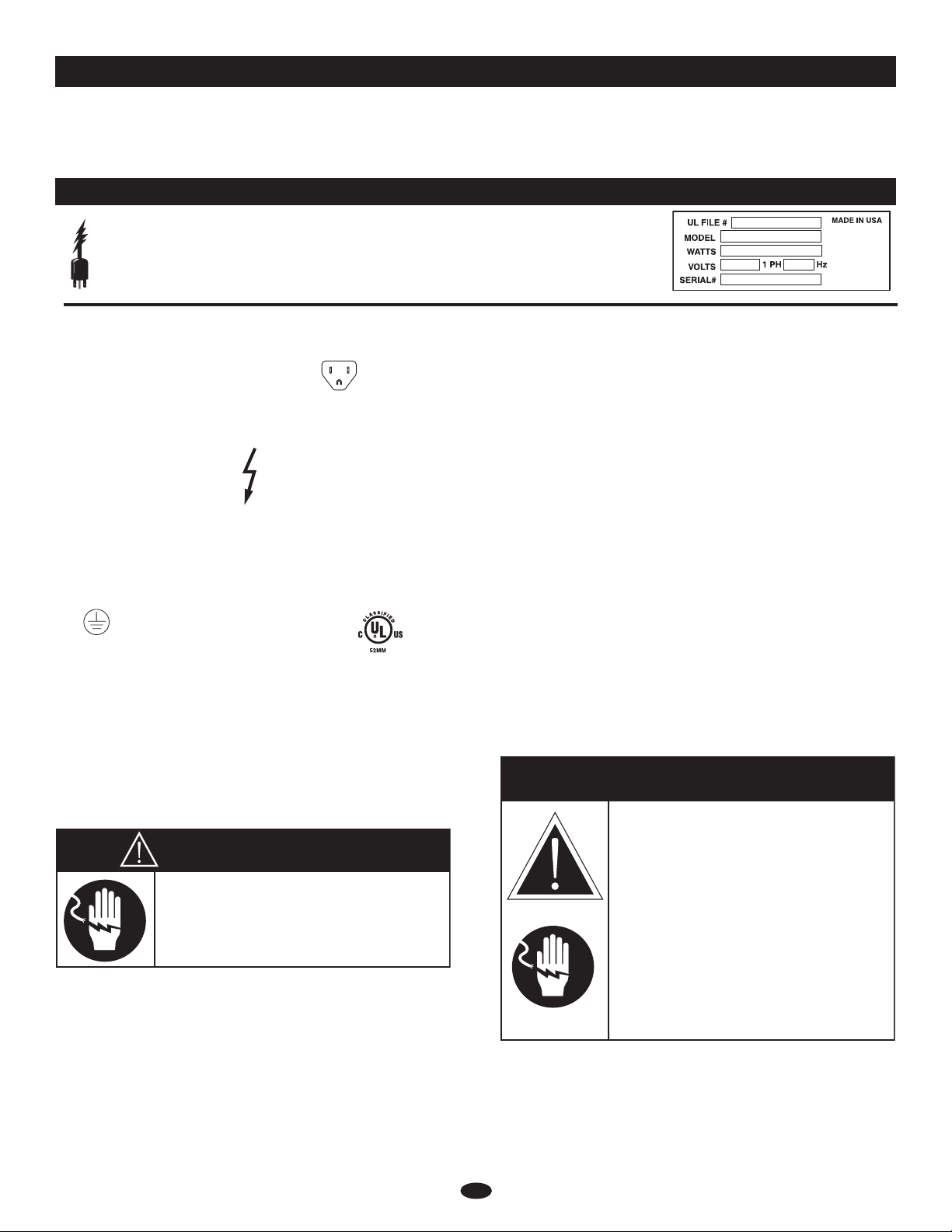
power cord that is ~2.5m in length.
WARNING: A risk of increased emissions or decreased
immunity may result if the power cord attached is altered or
a manufacturer supplied power cable is not used.
The P-2010-S should not be used adjacent to or stacked with
other equipment.
WARNING: observe to verify normal operation if it is
necessary to use adjacent to or stacked with other equipment.
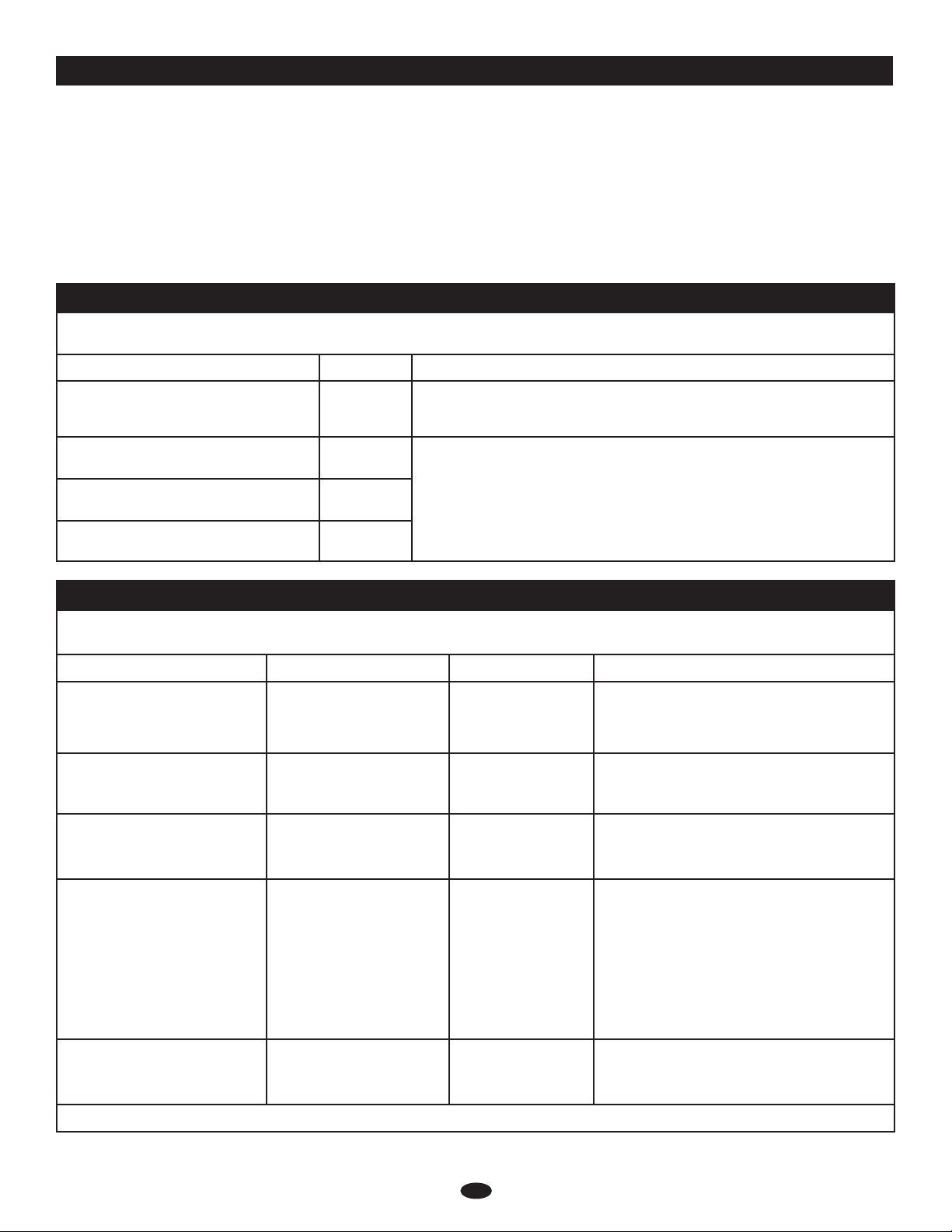
Guidance and manufacturer’s declaration – electromagnetic emissions
The Model P-2010-S is intended for use in the electromagnet environment specified below. The customer or the end user of the Model
P-2010-S should assure that it is used in such an environment.
Emissions test Compliance Electromagnetic environment - guidance
RF emissions
CISPR 11
Group 1 The Model P-2010-S uses RF energy only for it internal function. Therefore, its
RF emissions are very low and are not likely to cause any interference in nearby
electronic equipment.
RF emissions
CISPR 11
Class B The Model P-2010-S is suitable for use in all establishments, including domestic
establishments and those directly connected to the public low-voltage power
supply network that supplies buildings used for domestic purposes.
Harmonic emissions
IEC 61000-3-2
Class A
Voltage fluctuations/Flicker emissions
IEC 61000-3-3
Complies
Guidance and manufacturer’s declaration – electromagnetic immunity
The Model P-2010-S is intended for use in the electromagnet environment specified below. The customer or the end user of the Model
P-2010-S should assure that it is used in such an environment.
Immunity test IEC 60601 test level Compliance level Electromagnetic environment - guidance
Electromagnetic discharge (ESD)
IEC 61000-4-2
±6 kV contact
±8 kV air
±6 kV contact
±8 kV air
Floors should be wood, concrete or ceramic tile.
If floors are covered with synthetic material, the
relative humidity should be at least 30%.
Electrical fast transient/burst
IEC 61000-4-4
±2 kV for power supply lines
±1 kV for input/output lines
+2 kV for power
supply lines
Mains power quality should be that of a typical
commercial or hospital environment. The
P-2010-S does not have any input/output lines.
Surge
IEC 61000-4-5
±1 kV differential mode
±2 kV common mode
±1 kV differential
mode
±2 kV common mode
Mains power quality should be that of a typical
commercial or hospital environment.
Voltage dips, short interruptions
and voltage variations on power
supply input lines
IEC 61000-4-11
<5 % UT (>95 % dip in UT)
for 0.5 cycle
40 % UT (60 % dip in UT)
for 5 cycles
70 % UT (30 % dip in UT)
for 25 cycles
<5 % UT (>95 % dip in UT)
for 5 sec
<5 % UT (>95 % dip in
UT) for 0.5 cycle
40 % UT (60 % dip in
UT) for 5 cycles
70 % UT (30 % dip in
UT) for 25 cycles
<5 % UT (>95 % dip in
UT) for 5 sec
Mains power quality should be that of a typical
commercial or hospital environment. If the
user of the Model P-2010-S requires continued
operation during power mains interruptions,
it is recommended that the Model P-2010-S be
powered from an uninterruptible power supply or
a battery.
Power frequency (50/60 Hz)
magnetic field
IEC 61000-4-8
3 A/m 3 A/m Power frequency magnetic fields should be at
levels characteristic of a typical location in a
typical commercial or hospital environment.
NOTE UT is the a.c. mains voltage prior to application of the test level.

5
Guidance and manufacturer’s declaration - electromagnetic emissions
The Model P-2010-S is intended for use in the electromagnet environment specified below. The customer or the end user of the Model
P-2010-S should assure that it is used in such an environment.The P-2010-S is intended for use in the electromagnetic environment specified
below. The customer or the user of the P-2010-S should assure that it is used in such an environment.
Immunity test IEC 60601 test level Compliance level Electromagnetic environment - guidance
Portable and mobile RF communications equipment should be used no closer
to any part of the P-2010-S, including cables, than the
recommended separation distance calculated from the equation applicable to
the frequency of the transmitter.
Recommended separation distance
Conducted RF
IEC 61000-4-6
Radiated RF
IEC 61000-4-3
3 Vrms
150 kHz to 80 MHz
3 V/m
80 MHz to 2.5 GHz
3 V
3 V/m
d = [3.5/3] √P
d = [3.5/3] √P 80 MHz to 800 MHz
d = [7/3] √P 800 MHz to 2.5 GHz
where P is the maximum output power rating of the transmitter in watts
(W) according to the transmitter manufacturer and d is the recommended
separation distance in metres (m).
Field strengths from fixed RF transmitters, as determined by an
electromagnetic site survey,a should be less than the compliance level in each
frequency range.b
Interference may occur in the vicinity of equipment marked with the following
symbol:
NOTE 1 At 80 MHz and 800 MHz, the higher frequency range applies.
NOTE 2 These guidelines may not apply in all situations. Electromagnetic propagation is affected by absorption and reflection from
structures, objects and people.
a Field strengths from fixed transmitters, such as base stations for radio (cellular/cordless) telephones and land mobile radios, amateur radio,
AM and FM radio broadcast and TV broadcast cannot be predicted theoretically with accuracy. To assess the electromagnetic environment
due to fixed RF transmitters, an electromagnetic site survey should be considered. If the measured field strength in the location in which the
P-2010-S is used exceeds the applicable RF compliance level above, the P-2010-S should be observed to verify normal operation. If abnormal
performance is observed, additional measures may be necessary, such as reorienting or relocating the P-2010-S.
b Over the frequency range 150 kHz to 80 MHz, field strengths should be less than [VI] V/m.
Guidance and manufacturer’s declaration – electromagnetic immunityRecommended separation
distance between portable and mobile RF communications equipment and the model P-2010-S
The model P-2010-S is intended for use in an electromagnetic environment in which radiated RF disturbances are controlled. The customer
or the user of the Model P-2010-S can help prevent electromagnetic interference by maintaining a minimum distance between portable and
mobile RF communications equipment (transmitters) and the Model P-2010-S as recommended below, according to the maximum output
power of the communications equipment.
Rated maximum output
power of transmitter
W
Separation distance according to frequency of transmitter
m
150 kHz to 80 MHz 80 MHz to 800 MHz 800 MHz to 2.5 GHz
0.01 0.117 0.117 0.233
0.1 0.369 0.369 0.738
11.167 1.167 2.333
10 3.689 3.689 7.379
100 11.667 11.667 23.333
For transmitters rated at a maximum output power not listed above, the recommended separation distance d in meters (m) can be estimated using the equation
applicable to the frequency of the transmitter, where P is the maximum output rating of the transmitter in watts (W) according to the transmitter manufacturer.
NOTE 1 At 80 MHz and 800 MHz, the separation distance for the higher frequency range applies.
NOTE 2 These guidelines may not apply in all situations. Electromagnetic propagation is affected by absorption and reflection from structures, objects and people.

GENERAL INFORMATION
6
This warming cabinet is designed to elevate and
maintain blanket temperatures to a level which will
increase patient comfort.
2.3 cubic feet of capacity in a single cavity countertop
warming cabinet with 22 gauge stainless steel exterior
and door with handle and hinges designed to withstand
heavy usage. The cabinet is equipped with low-heat-
density electrothermal cable mounted against the walls,
eliminating the need for a heat circulating fan. Interior
contains one (1) epoxy-coated blanket support assembly.
The cabinet is furnished with four (4) 1-1/4” (31mm)
non-skid rubber feet.
The cabinet is controlled by one (1) ON/OFF power switch
and a temperature control knob that is adjustable from 16°C
(60°F) to 92°C (200°F). The unit includes a digital display,
and a temperature display light that indicates that the
cabinet has reached the desired warming temperature.
DANGER
AT NO TIME SHOULD THE INTERIOR
OR EXTERIOR BE STEAM CLEANED,
HOSED DOWN, OR FLOODED WITH
WATER OR LIQUID SOLUTION OF
ANY KIND. DO NOT USE WATER JET
TO CLEAN.
SEVERE DAMAGE OR
ELECTRICAL HAZARD
COULD RESULT.
WARRANTY BECOMES VOID IF
APPLIANCE IS FLOODED
DANGER
DO NOT use this warming cabinet
in the presence of flammable
anesthetic mixture (with air or
with oxygen or nitrous oxide).
THIS COULD RISK AN EXPLOSION!
NOTE
The temperature inside the warmer’s
cavity shall never exceed maximum
permissable temperature plus the
tolerance. (250°F [121°C] +10%)
NOTE
Environmental conditions for operation:
Maximum ambient room temperature of 89°F (32°C).

7
DIMENSIONS
C
L
ELECTRICAL
CONNECTION
1.5" (38mm)
FROM TOP
16.25"
(411mm)
Cavity
13.25"
(337mm)
Cavity 14"
(365mm) Cavity 21.5" (546mm)
20.3" (516mm)
20.8" (528mm)
27" (685mm)
41" (1035mm)

1. The appliance should be plugged into a hospital grade,
NEMA 5-15P receptacle. The unit requires 1" (25mm)
clearance on sides, back, and bottom.
2. Turn on the power circuit breaker switch,
which is located at the back of the appliance.
It is a rocker-type switch with international
ON (I) and OFF (O) markings.
3. PREHEAT AT 200°F (93°C).
Rotate the control knob to 200°F (93°C). The Set
temperature will appear in the digital display and the
temperature display light will illuminate. Press the
Temperature Display Button at any time to display the
Actual inside air temperature.
To toggle between Set and Actual Temperatures:
Factory default is to display Set temperature in the digital
display. To display Actual temperature:
1. With the control ON, press and hold the Temperature
Display Button for 5 seconds. The control will show
ACT , then show the Actual temperature.
2. Repeat to toggle to Set point SET .
3. Press the Temperature Display Button at any time to
display the alternate temperature.
To toggle between Fahrenheit and Celsius:
The factory default is Fahrenheit. To change to Celsius:
1. With the control OFF (i.e. Temperature Control Knob
set to the OFF position), press and hold the Temperature
Display button for 5 seconds.
2. The control will show ° for 3 seconds to verify
selection and then show the temperature in ºC.
3. Repeat to toggle to Fahrenheit.
Note: With a power failure, the control will retain the ºC or
ºF setting selected by the user when power is restored.
4. The temperature display LED will illuminate when the
control is heating the unit.
5. LOAD THE CHAMBER WITH 100% COTTON
BLANKETS. DO NOT WARM SYNTHETIC BLEND
FABRICS OR ITEMS CONTAINING PLASTIC, RUBBER
OR METAL SNAPS, STUDS, HOOKS, ETC.
Check that the epoxy-coated blanket support assembly is
in place. This blanket support assembly MUST be used to
hold blankets. A full load of blankets will take 1-2 hours to
reach optimum temperature. Make certain the cabinet door
is securely closed after initial loading and following each
blanket removal.
Note: Do not block sensor by overloading cabinet
with blankets.
6. ROTATE LOAD OF BLANKETS DAILY.
Rotate the blankets at the bottom of the load to the top to
ensure equal usage. Failure to rotate blankets can cause
blankets to discolor.
Note: Avoid using flammable cabinet cleaning agents, as well
as blanket cleaning agents that cause fabric to become
brittle over time.
8
OPERATIONAL PROCEDURES
CAUTION
DO NOT OVERLOAD CABINET.
BLANKETS MUST NOT EXCEED HEIGHT OF
SUPPORT ASSEMBLY. ALLOW 1" GAP
BETWEEN LOWER BLANKETS AND SHELF.
Digital
Display
Temperature
Control Knob
Temperature
Display Button
Temperature
Display LED
POWER
CIRCUIT BREAKER
SWITCH
CAUTION
BLANKET SUPPORT ASSEMBLY AND SHELF
MUST BE USED WHEN WARMING BLANKETS.

9
CLEANING AND PREVENTIVE MAINTENANCE
PROTECTING STAINLESS STEEL SURFACES
It is important to guard against corrosion
in the care of stainless steel surfaces.
Harsh, corrosive, or inappropriate
chemicals can completely destroy the
protective surface layer of stainless
steel. Abrasive pads, steel wool, or
metal implements will abrade surfaces
causing damage to this protective coating and will eventually
result in areas of corrosion. Even water, particularly hard water
that contains high to moderate concentrations of chloride, will
cause oxidation and pitting that result in rust and corrosion. In
addition, many acidic spills left to remain on metal surfaces are
contributing factors that will corrode surfaces.
Proper cleaning agents, materials, and methods are vital to
maintaining the appearance and life of this appliance. Spilled
items should be removed and the area wiped as soon as
possible but at the very least, a minimum of once a day. Always
thoroughly rinse surfaces after using a cleaning agent and wipe
standing water as quickly as possible after rinsing.
CLEANING AGENTS
Use non-abrasive cleaning products designed for use on
stainless steel surfaces. Cleaning agents must be chloride-free
compounds and must not contain quaternary salts. Never use
hydrochloric acid (muriatic acid) on stainless steel surfaces.
Always use the proper cleaning agent at the manufacturer’s
recommended strength. Contact your local cleaning supplier
for product recommendations.
CLEANING MATERIALS
The cleaning function can usually
be accomplished with the proper
cleaning agent and a soft, clean
cloth. When more aggressive
methods must be employed, use a non-
abrasive scouring pad on diffi cult areas
and make certain to scrub with the visible
grain of surface metal to avoid surface
scratches. Never use wire brushes, metal scouring pads, or
scrapers to remove residue.
ANNUAL PREVENTATIVE MAINTENANCE
1. Ensure that the correct Operation and Care Manual is
available to all users.
2. Ensure that all users have been properly trained in
unit’s operation.
3. Do not exceed the unit’s capacity.
4. Inspect condition of plug and cord. Replace if damaged.
5. Clean dust from outer vents surrounding the unit and
around top of bonnet.
6. Check door gasket integrity. Are there any tears? Is the
gasket worn or loose? Make sure seal is tight to unit body.
Replace gasket if integrity is compromised.
7. Check air temperature sensor mount on the interior of
chamber. Is the metal guard in place? Are the wires in
good condition?
8.
Check the blanket support assembly and shelf (if applicable).
Is the assembly in place? Are any pieces missing?
9. Check basket and side rail condition (if applicable). Do
baskets move smoothly and freely?
10. Check caster or leg condition. Ensure mounting bolts and
assembly is secure.
11. Check control panel overlay condition. Are there any tears
or excessive wear on the graphic? Does the control work
properly when buttons are pushed?
12. Check that all control LEDs light up as applicable.
13. Is the Set Temperature comparable to the Actual temperature
displayed? If not, control needs calibration. Call Service.
Contact Service for immediate repair if any of the above
problems exist.
CAUTION
TO PROTECT STAINLESS STEEL
SURFACES, COMPLETELY AVOID
THE USE OF ABRASIVE CLEANING
COMPOUNDS, CHLORIDE BASED
CLEANERS, OR CLEANERS
CONTAINING QUATERNARY SALTS.
NEVER USE HYDROCHLORIC ACID
(MURIATIC ACID) ON STAINLESS
STEEL. NEVER USE WIRE
BRUSHES, METAL SCOURING
PADS OR SCRAPERS.
N
O
W
I
R
E
B
R
U
S
H
E
S
N
O
S
T
E
E
L
P
A
D
S
N
O
S
C
R
A
P
E
R
S

The cleanliness and appearance of this equipment will contribute considerably to its operating
efficiency. Make certain the cabinet and door gasket are kept free of any debris that may accumulate.
Good equipment that is kept clean works better and lasts longer.
CLEAN THE UNIT REGULARLY:
1. Disconnect the cabinet from the power source.
2. Remove all detachable items such as blanket support assembly and shelf. Clean these
items separately.
NOTE: Avoid the use of abrasive cleaning compounds, chloride based cleaners, or cleaners
containing quaternary salts. Never use hydrochloric acid (muriatic acid) on stainless steel.
3. Clean the interior metal surfaces of the cabinet with a damp cloth and any mild
commercial detergent. Avoid the use of abrasive cleaning compounds. Rinse surfaces
by wiping with sponge & clean warm water. Remove excess water with sponge and
wipe dry with a clean cloth or air dry. Leave doors open until interior is completely dry.
4. Interior can be wiped with a sanitizing solution after cleaning and rinsing. This solution must be approved for use
on stainless steel surfaces. Replace blanket support assembly.
5. Clean the exterior of the cabinet with a cleaner recommended for stainless steel surfaces. Spray the cleaner on a clean
cloth and wipe with the grain of the stainless steel.
6. Clean the window glass with a standard commercial glass cleaner.
7. Wipe control panel, door vents, door handles, and door gaskets thoroughly since these areas harbor debris.
8. Wipe door gaskets and control panel dry with a clean, soft cloth.
9. To help maintain the protective film coating on polished stainless steel, clean the exterior of the cabinet with a
cleaner recommended for stainless steel surfaces. Spray the cleaning agent on a clean cloth and wipe with the grain
of the stainless steel.
Always follow appropriate state or local health (hygiene) regulations regarding all applicable cleaning and
sanitation requirements.
CARE AND CLEANING
10
(Listed as Ordinary Equipment.)
DANGER
DISCONNECT UNIT FROM
POWER SOURCE BEFORE
CLEANING OR SERVICING.
DANGER
AT NO TIME SHOULD THE INTERIOR
OR EXTERIOR BE STEAM CLEANED,
HOSED DOWN, OR FLOODED WITH
WATER OR LIQUID SOLUTION OF
ANY KIND. DO NOT USE WATER JET
TO CLEAN.
SEVERE DAMAGE OR
ELECTRICAL HAZARD
COULD RESULT.
WARRANTY BECOMES VOID IF
APPLIANCE IS FLOODED

11
TROUBLESHOOTING ERROR CODES
Error
Code Description/Results
Possible Cause
Service Required
E-10 Air Sensor Fault (shorted)
Inoperative Unit
Air sensor is shorted.
Air sensor defective?
Test air sensor by placing sensor in ice water bath 32°F (0°C) and using an
ohmmeter set on the ohm scale. The reading should be 1000 ohms resistance. If it is
more than 20 ohms higher or lower, sensor needs to be replaced. If Ohm reading is
1000, replace display. If Ohm reading is not 1000, replace sensor.
E-11 Air Sensor Fault (open)
Inoperative Unit
Air sensor is open or connection failure.
Air sensor defective? See above for air sensor test.
E-30 Under temperature
Oven will not reach set temperature
Unit door closed? Does door gasket need replacement? Defective air sensor or
probe? Defective solid state relay? Bad wire connections or open heating cable?
If none of the above, contact Pedigo Service Department.
E-31 Over temperature
Unit will shut down
Unit has exceeded its maximum allowable set temperature by 25 degrees for at
least 3 minutes. Unit will shut down.
Defective sensor or poor sensor connection?
Defective relay?
Shorted heater element?
If none of the above, contact Pedigo Service Department.
E-70 Configuration error
Inoperative Unit
Check wire diagram for correct DIP switch settings. (Diagram is located under
the unit’s top cover behind the control.) If error code persists, contact Pedigo
Service Department.
E-82 or
E-83
EEPROM Error - Bad Checksum
Inoperative Unit
Contact Pedigo Service Department for help resetting the control.
E-90 Button shorted
Inoperative Control
Stuck button on control panel. Check buttons.
If control is still inoperative, contact Pedigo Service Department.
E-91 Input failure Contact Pedigo Service Department.
-AC- Power Failure Press any key to acknowledge.

12
* NOT SHOWN
LOC DESCRIPTION QTY P-2010-S P/N
ELECTRICAL HARDWARE
1. CIRCUIT BREAKER SWITCH 1SW-33826
2. CORDSET, HOSPITAL GRADE, 10ft (3m) 1E3025CD
3. CONTROL, MANUAL 15012186
4. CONNECTOR, DOUBLE QUICK 1BU-34836
5. MANUAL HI-LIMIT RESET 1TT-33476
6. AUTO RESET HI-LIMIT 1TT-34350
7. PROBE* 1PR-34494
MECHANICAL HARDWARE
8. BLANKET INSERT, BOTTOM* 1SH-25907
9. BLANKET INSERT, SIDES* 2SR-25906
10. BOTTOM SPOT COVER* 15011147
11. BUMPER FEET 4FE-29203
12. CASING 11011001
13. CONTROL PANEL OVERLAY* 1PE-28978
14. DOOR ASSEMBLY 15011145
15. DOOR GASKET* 6ft (1829mm) GS-2398
16. DOOR HANDLE WITH STRIKER 1HD-2007
17. HINGE SET (1 PAIR OF 2 HINGES) 1HG-2015
18. THERMOSTAT KNOB* 1KN-26568
19. TOP WELD ASSEMBLY 15011144
OPTIONS AND ACCESSORIES
20. CASTER STAND ASSEMBLY WITH 5” (127mm) CASTERS 1CONTACT FACTORY
21. LEG STAND ASSEMBLY WITH 6” (152mm) LEGS 1CONTACT FACTORY
PART NUMBERS AND DRAWINGS ARE SUBJECT TO CHANGE WITHOUT NOTICE.
CABLE REPLACEMENT KITS P/N
P-2010-S
KIT 4873
CABLE HEATING ELEMENT CB-3044 54 ft (16m)
CUP BUSHING BU-3106 2
HI-TEMP TAPE TA-3540 1 ROLL
HEX NUT NU-2215 4
INSULATION CORNER IN-3488 8 ft (2m)
INSULATING SLEEVE SL-3063 2
RING CONNECTOR CR-3226 2
SHOULDER BUSHING BU-3105 2
STUD, 10-32 ST-2439 2
HEATING CABLE REPLACEMENT KITS*
*NOT SHOWN
SERVICE PARTS LIST (SEE SERVICE VIEW ON FOLLOWING PAGE)

13
1
2
3
4
5
6
19
16
14
12
17
11
PART NUMBERS AND DRAWINGS ARE SUBJECT TO CHANGE WITHOUT NOTICE.
10

14
REFER TO WIRE DIAGRAM UNDER TOP COVER OF P-2010-S FOR MOST CURRENT VERSION
PART NUMBERS AND DRAWINGS ARE SUBJECT TO CHANGE WITHOUT NOTICE.

TRANSPORTATION
DAMAGE AND CLAIMS
All Pedigo Products, Inc. equipment
is sold F.O.B. shipping point, and when
accepted by the carrier, such shipments
become the property of the consignee.
Should damage occur in shipment, it is a matter between the carrier
and the consignee. In such cases, the carrier is assumed to be
responsible for the safe delivery of the merchandise, unless negligence
can be established on the part of the shipper.
1. Make an immediate inspection while the equipment is still in the
truck or immediately after it is moved to the receiving area. Do
not wait until after the material is moved to a storage area.
2. Do not sign a delivery receipt or a freight bill until you have made
a proper count and inspection of all merchandise received.
3. Note all damage to packages directly on the carrier’s
delivery receipt.
4. Make certain the driver signs this receipt. If he refuses to sign,
make a notation of this refusal on the receipt.
5. If the driver refuses to allow inspection, write the following on
the delivery receipt:
Driver refuses to allow inspection of containers for
visible damage.
6. Telephone the carrier’s offi ce immediately upon fi nding damage,
and request an inspection. Mail a written confi rmation of the
time, date, and the person called.
7. Save any packages and packing material for further inspection by
the carrier.
8. Promptly fi le a written claim with the carrier and attach copies of
all supporting paperwork.
We will continue our policy of assisting our customers in collecting
claims which have been properly fi led and actively pursued. We
cannot, however, fi le any damage claims for you, assume the
responsibility of any claims, or accept deductions in payment
for such claims.
PEDIGO PRODUCTS, INC.
LIMITED WARRANTY
Pedigo Products, Inc. warrants to the original purchaser that any
original part that is found to be defective in material or workmanship
will, at our option, subject to provisions hereinafter stated, be
replaced with a new or rebuilt part.
The labor warranty remains in effect one (1) year from installation or
fi fteen (15) months from the shipping date, whichever occurs fi rst.
The parts warranty for the cavity fan motor remains in effect one (1)
year from installation or fi fteen (15) months from the shipping date,
whichever occurs fi rst. The parts warranty on all other parts remains
in effect three (3) years from installation or thirty-nine (39) months
from the shipping date, whichever occurs fi rst.
This warranty does not apply to:
1. Calibration
2. Equipment damage caused by accident, shipping, improper
installation or alteration.
3. Equipment used under conditions of abuse, misuse, carelessness
or abnormal conditions including equipment subjected to
harsh or inappropriate chemicals including but not limited to
compounds containing chloride or quaternary salts, poor water
quality, or equipment with missing or altered serial numbers.
4. Any losses or damage resulting from malfunction, including loss
of contents or consequential or incidental damages of any kind.
5. Equipment modifi ed in any manner from original model,
substitution of parts other than factory authorized parts, removal
of any parts including legs, or addition of any parts.
6. Collateral or incidental damage as a direct result of servicing
equipment built into a wall structure is not covered under
warranty. It is the responsibility of the owner to bear all
expense related to structural repairs including, but not limited
to, external electrical connections and wiring, and the removal
or replacement of caulk, grout, tile, or wall covering of any
kind. A service access panel for built-in equipment installations
is strongly recommended.
This warranty is exclusive and is in lieu of all other warranties,
expressed or implied, including the implied warranties of
merchantability and fi tness for purpose. In no event shall the
Company be liable for loss of use, loss of revenue, or loss of contents
or revenue, or for indirect or consequential damages. This warranty
is in lieu of all other warranties expressed or implied and Pedigo
Prodcuts, Inc. neither assumes or authorizes any persons to assume
for it any other obligation or liability in connection with Pedigo
Products, Inc. equipment.
Pedigo Products, Inc.
Record the model and serial numbers of the unit for easy
reference. Always refer to both model and serial numbers in your
correspondence regarding the unit.
Model: ___________________________________________________
Serial Number: ____________________________________________
Purchased From: __________________________________________
Date Installed: ______________ Voltage: __________________
Pedigo Products, Inc
4000 S.E. Columbia Way • Vancouver, WA 98661 • U.S.A.
Phone: 800.822.3501 • Fax: 360.696.1700 • www.pedigo-usa.com

MN-29621 • 05/21
Other manuals for P-2010-S
1
Table of contents
Other Pedigo Warming Drawer manuals
Popular Warming Drawer manuals by other brands

Fisher & Paykel
Fisher & Paykel 9 Series Quick reference guide

Fisher & Paykel
Fisher & Paykel W30SDEI installation guide

Viking Range
Viking Range RVEWD installation guide

Klarstein
Klarstein 10035698 manual

DCS
DCS WD1-30-SSOD Installation instructions and user guide

Thermador
Thermador WDC30J Use and care guide