PEERLESS Partner PP-120 Instruction manual

Partner ®
Water Heater
•RTNER _!
Installation,
Operation Et
Maintenance
Manual
pr=-ERLES$ o
PARTNER °
IN_l_t FI_D WATER HEATE_

4 Sizes 37 to iig Gallon Capacity 295 to 513 GPH First Hour Rating
Uses the Existing Boiler as its Heat Source
•No Separate Chimney or Burner Required
•Functions as an Additional Heating Zone
Long Lasting Stainless Steel Construction
•High Grade 316L Stainless Steel Tank
•Superior Corrosion Resistance
•Drain Tapping for Draining and Flashing Tank
Cupronickel Fin-Tube Heat Exchanger
•Provides Maximum Heat Transfer for Rapid Recovery Rates
•Resists Mineral Buildup and Sealing Deposits
•1" Boiler Connections Provide for Minimum Pressure Drop thru Heat Exchanger
Minimal Standby Temperature Loss
•2" Polyurethane Foam Insulation
•Less Than 1/2 ° Fper Hour Standby Loss
•Minimal Boiler F#ing to Maintain Temperature
•Provides More Hot Water with Reduced Boiler Water Temperatures
Maintenance-Free Plastic Jacket
•Will Not Scratch or Rust
•Color Coordinated to Match Peerless Boiler Jackets
Enclosed Thermostat Well
•Control Can Be changed Without Draining Tank
•Honeywell Well Type Adjustable Control
•T & P Relief Valve
•Cupronickel Fin & Tube Heat Exchanger
•High Grade 316L Stainless Steel Tank
• Plastic Jackel with 2" Polyurethane Foom
Insulation
one-year tvatTanty.tot tilt, P(,(,Hes.,; Pcwlnet" lndirz_cI Fir_'d Water 1tearer: Peerless also ptz)vicles a
limited, l!]_linle tL,arr_ltlty agamsl leaks.t}om th(_ h('aa'rsjctch_'t, latllc, of h('(tl t'xchculgcr [(_F r('._icl_'tJliol applicatiotts aiid o limit
('d..]lv(_-y_,c2r tt,6ltTOlll_] ttgoitl_l I(?c_ks./}om I]lc h(!(llt'l'N,/(l(']t-_'l I(tt!]¢ or ]|C(JI t_VCh(Itl(]('!'.t()l ('Ol!ltlR'tY'i(ll tlpl)licoliotl._. [Jl('(t._(" Cotl.';ttlt
P¢'crlt's_; Boilers.l_r complett" [L'OIT(II1QI iq/ormation.
Peerless Boilers * 610-367-2153 * www.peerless heater.com
FAB PARTNER R2 (303 IM)
Prlrll_?cI it1 L} _ A

PEERLESS
PARTN E R °
INDIRECT-FIRED WATER HEATER
PARTNER ®
Modern Coil Design
uMinimal Standby Temperature
Loss
uRapid Recovery Rate
Long Lasting Stainless Steel
Construction
QEasy Installation
QNo Separate Chimney or Burner
Needed
The Peerless Partner _indirect-fired water heater provides a true
advancement in hot water generation. By utilizing the existing boiler
as its heat source, the burner fires only when necessary and
transfers heat energy through a highly efficient cupronickel, fin-tube
heat exchanger. The heater functions as a separate heating zone
and water movement is regulated from the boiler through the heater
coil by a separate circulator or zone valve.
The modem coil design of the Peerless Partner indirect-fired
water heater provides maximum heat transfer efficiency and resists
mineral buildup that discolors water. Old style coils can produce
discolored tapwater that affects taste and leaves blue bathtub rings.
The heater's cupronickel heat exchanger is highly resistant to any
scaling deposits and is positioned so entering water provides
scrubbing action, eliminating the need for chemical cleanings.
The domestic hot water is stored in a high-grade 316L stainless
steel tank. Two inch foam insulation keeps the water hot with a
standby loss of less than 1/2° F per hour. This allows the boiler to
stay off most of the day and night. The result is more hot water
with reduced boiler water temperatures and drastically reduced
standby losses.
The Peerless Partner indirect-fired water heater has two or more
times the recovery rate of gas-fired water heaters and supplies as
much as five times the amount of hot water as a comparably sized
electric water heater.
This heater is an ideal replacement for existing water heaters. It can
also be used for new applications. A vent or stack is not required. The
tank's light weight makes it very easy to position. The plastic jacketing is
maintenance free and does not scratch or rust.
The Peerless Partner indirect-fired water heater comes equipped
with an adjustable, well-type Honeywell control and a T& P relief
valve as standard equipment.
Model Storage
Number Capacity
PP-40 37 gallons
PP-6O 57 gallons
PP-80 77 gallons
PP-120 119 gallons
Heat
Pressure Exchange First Hour Ratings*
Test Working Su #ace @140 ° @115°
300 PSI 150 PSI 15 sq ft. 200 gallons 295 gallons
300 PSI 150 PSI 15 sq ft 255 gallons 347 gallons
300 PSI 150 PSI 34 sq ft 300 gallons 400 gallons
300 PSI 150 PSI 34 sq. ft. 385 gallons 513 gallons
*Based on 90" F rise. 55_/145 _ with 180° F boiler water First hour rating is only one factor in product selection Refer to Installation
h_structions for additional information

)EERLESS PARTNER®SPECS
Floor To
= High-Grade 316L Stainless Steel Tank Model Boiler Boiler Domestic
Number Height Diameter Supply Return In/Out
•Maintenance-Free Plastic Jacket PP-40 521/2" 19v4" 9" 4w' 3" 46"
PP-6O 52V2" 23V4" 9" 41/2" 3" 46"
= 2" Polyurethane Foam Insulation PP-80 72" 24" 29" 6 6" 66"
•Cupronickel, Fin-Tube Coil Assembly ___
• Enclosed Thermostat Well
• Adjustable Honeywell Control
• T&P Relief Valve
Domestic
Water
Connections
¾" N.P.T. Male
1" N.P.T. Male
1V2"N.P.T. Male
1_/2"N.P.T. Male
Approx.
Shipping
Model Weight
Number Length Width Height (Ibs.)
PP-40 2OW' 20V2" 56" 78
PP*6O 24V2" 24V2" 56" 98
PP-80 25V2" 251/2" 74" 139
PP-120 29" 29" 78" 206
Hot Water Outlet,
T&P Relief Valve
Domestic Water
Connections (See
Dimensional Data)
Cold Water
Inlet & Drain
FLOOR
2" Polyurethane Foam
-- Insulation On Outside,
Less Than 1/2 °F Per
Hour Heat Loss R17
-- 316L Stainless Steel Tank
-- Plastic Jacket
Enclosed Thermostat Weft for
Adjustable Honeywell Control
(Boiler Water Supply
& Return 1" Threaded)
Boiler Supply
Cupronickel
Coil Assembly
Boiler Return
The residential warranty covers:
--the entire water heater, one year from date of installation.
---outside jacket, inner tank, or heat exchanger, lifetime.
The commercial warranty covers:
--the entire water heater, one year from date of installation.
--outside jacket, inner tank, or heat exchanger, second
through fifth year.
*Before purchase contact your installing contractor for complete warranty
information.
PEERLESSHEATERCO.
231 North Walnut Street
Boyer_own, PA 19512-1021
Phone: 610-367-2153 • FAX: 610-369-3284
www.peerless-heater.com
CUT pARTNER £2 (11/02 10M} Pr_nt_ d _n U S A _'y2002 Peerless Heater Cot_tpany

1. The following guidelines apply to residential systems only. For commercial or institutional installations contact
your local Peerless Heater Company representative.
2. Determine the quantity of domestic hot water required. Factors to consider:
a. Estimate typical peak hour demand. Determine the general time of day (morning, noon, evening) when the
most hot water is used. Use chart below to determine potential maximum usage.
Estimate of Peak Domestic Hot Water Usage
AverageGallons of Times Used During Gallons Used in
Use Hot Water per Usage One Hour One Hour
Shower 20 x -
Bath 20 x =
Shaving 2 x =
Hands and Face Washing 4 x =
Hair Shampoo 4 x =
Hand Dish Washing 4 x =
Automatic Dish Washing 14 x =
Food Preparation 5 x =
Wringer Clothes Washer 26 x =
Automatic Clothes Washer 32 x =
Total Peak Hour Demand =
b. Estimate unusual peak draw demand. Whirlpool baths, hot tubs, and multiple head showers require
large quantities of hot water in a short period of time. Contact fixture manufacturer for quantity of water
required. Generally speaking, these circumstances can only be met with larger storage volumes.
c. Domestic Water Temperature. Most residential usage will be satisfied with 119°F water, the temperature
setting recommended by the Consumer Product Safety Commission. Some applications such as laundry
and dishwashers may require a higher temperature.
Ratings can be improved by increasing Peerless ®Partner ®thermostat setting and using a mixing valve to
temper the hot water to the proper temperature. When temperatures greater than 119°F are required, use
amixing valve at the outlet of the water heater or anti-scald fittings at point of use.
Water temperatures over 125°F can cause severe burns instantly, or
death from scalds.
Children, disabled, and elderly are at the highest risk of being scalded.
See instruction manual before setting temperature at water heater.
Feel water before bathing or showering.
Temperature limiting valves are available, see manual.
The Peerless Partner indirect-fired water heater is deemed to be used in a "commercial setting" if at
any time the unit is operated at a temperature over 150°F. Refer to warranty for additional information.

d. Boiler. PP-80, PP-120, PP-80-DW, and PP-120-DW require full boiler output listed in Table 1. If boiler is a
Category IV condensing boiler, such as Peerless" Pinnacle', the above Peerless _'Partner _"models can be
used with reduced boiler output. If boiler output is less than shown in Table 1 reduce first hour rating as
shown in Table 2. Increase boiler size only if first hour rating does not meet estimated peak hour usage.
If a boiler with listed output is not needed for space heating, an alternative to a PP-80/120 would be
a PP-40 or PP-60 piped in series with an unfired storage tank (i.e. electric water heater without heating
elements energized).
Use a water boiler only. The Peerless Heater Company cannot recommend the use of steam boilers at this
time. Contact factory for additional information.
e. Domestic water priority. First hour ratings may be less than published when boiler output is shared with
space heating. Generally a consumer will notice a drop in domestic water temperature before a drop in
space heating temperature. Giving domestic water production priority by directing entire boiler output to
Peerless Partner will maximize domestic water output. However, prioritization controls could result in an
unacceptable drop in space heating temperature when large quantities of domestic hot water are used,
and a prioritization control malfunction could result in loss of space heating.
3. Multiple Water Heaters. Peak domestic water usage (first hour rating) or unusual peak draw may not be met
with a single water heater. Multiple units can be installed as either a bank of tanks acting as a single unit, or
as multiple individual units sized and located for specific draw situations.
Table 1: Peerless Partner Ratings
Model
No.
PP-40
PP-80
PP-80
PP-120
PP-40-DW
PP-60-DW
PP-80-DW
PP-120-DW
Fi_tHourRating'[gallons]
140°F 115OF
212 292
266 370
330 440
423 564
172 251
204 288
283 391
37O 515
MinimumBoilerOutputqoAchieve
FimtHourRating[Btu_rhour]
141,000
174,000
212,000
269,000
115,000
188,000
220,000
252,000
UseableHotWater
[U.S.Gallons]3
28
46
64
94
28
46
84
94
HeatExchanger
SurfaceArea[ft_J
2O
20
34
34
20
20
20
2O
1. First hour rating based on heating water from 50°F to 140°/115°F with 180°F boiler water temperature. Gas- and oil-fired
and electric water heater first hour ratings based on DOE test procedure using 90°F temperature rise (55°F to 145°F).
2. Net I=B=R Output, Water
3. Useable hot water based on recent completion of recovery period, but no additional boiler input after draw begins.

Table 2: First Hour Ratings for Reduced Boiler Output
BoilerOutput
[Btuperhour]
40,000
60,000
80,000
100,000
120,000
140,000
160,000
180,000
200,000
220,000
240,000
260,000
BoilerOutput
140°F
68
99
130
152
182
PP-40'
115°F
94
138
180
210
251
140°F
160
176
181
206
pp-60 _115°F
221
244
251
309
pp-802_ 140°F
m
216
251
290
335
345
399
460
pp-40-DW I pp-60-DW_
140°F 115°F
216 297
223 -305
230 314
269 367
311 424
359 489
pp-80-DW,_
pp-120_115F
333
384
444
457
470
543
627
pp-120-DW2_
[Btuperhour]
40,000
60,000
80,000
100,000
120,000
140,000
160,000
180,000
200,000
140°F
57
85
115
143
115°F
78
117
158
197
140°F
66
100
133
156
166
171
189
200
115°F
91
139
181
215
227
236
281
272
140°F
130
147
160
178
192
210
224
243
265
115°F
179
203
222
243
265
289
309
335
366
1. 180°F Boiler Water
2. 200°F Boiler Water
3. Due to condensation in boiler, reduced output not recommended for PP-80, PP-120, PP-80-DW, and
Category IV condensing boilers, such as Peerless Pinnacle, can be used for reduced output.
140°F
136
155
168
186
199
226
251
278
361
PP-120-DW.
115°F
186
215
233
255
272
3O8
347
380
409
Table 3: First Draw at 140°F '.2(in Minutes)
Model DomesticWaterFlowRate[gpm]
No. 2.0 2.5 3,0 3.5 4.0 4.5 5.0 5,5 6,0 6.5 7.0 7.5
PP-40 16 14 12 10 9 87 6 5.5 5 4.2 3.7
PP-60 .... 30 24 20 17 10.3 9.5 8.2 7.8 7.1 6.1
PP-80 ............ 14 13 12 11.1 10.5 8.5
PP-120 ............ 20 18 16 15 14 12.5
PP-40-DW 16 14 12 10 9 8 7 6 5.5 5 4.2 3.7
PP-60-DW .... 30 24 20 17 10.3 9.5 8.2 7.8 7.1 6.1
PP-80-DW ............ 14 13 12 11.1 10.5 8.5
PP-120-DW ............ 20 18 16 15 14 12.5
**Unlimited hot water available at specified flow rate.
1. Based on cold start boiler with output listed in Table 1.
2. For minutes of domestic water flow at 115°F, multiply by 1.56.
1. Read these instructions completely before starting installation.
2. FOR YOUR SAFETY: Do not store or use gasoline or other flammable vapors or liquids in the vicinity of this
or any other appliance. Controls on this appliance could ignite vapors causing an explosion.
3. Install in accordance with the requirements of the authority having jurisdiction. In the absence of such
requirements, appliance must be wired in accordance with the National Electrical Code, ANSI/NFPA 70.

This product complies with 1990 N.S.P.C. provided: (1) the boiler water, including additives, is practically non-
toxic, having a toxicity rating or class of 1, as listed in Clinical Toxicology of Commercial Products, 5thedition;
and (2) the boiler water pressure is limited to a maximum of 30 psig by an approved safety or safety relief valve.
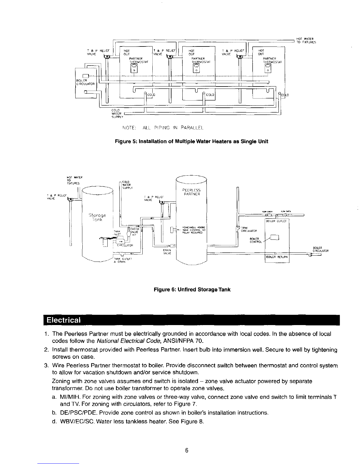
4. Peerless Partner(s) may be located adjacent to boiler to reduce piping heat loss or central to points of use to
reduce response time to fixtures.
a. Install indoors in an area not exposed to freezing temperatures. De not install outdoors.
b. Position with adequate clearance for service and maintenance. Provide access to thermostat, temperature
and pressure relief valve, and drain valve.
c. Protect surrounding area and lower floors from damage due to leakage from temperature and pressure
relief valve, drain valve, boiler or domestic water piping, and tank. Locate water heater near a floor drain or
in a drain pan suitable for the capacity of the water heater.
d. Install on level surface. Water heater must be kept in vertical position.
5. Suggested equipment list. See PIPING for additional information.
a. Water Heater Thermostat: Provided.
b, Temperature and Pressure Relief Valve: Provided.
c. Brass Drain Valve: 1 per water heater.
d. Brass Tee's: 2 per water heater.
e, Heat Exchanger to Boiler Piping: 1 inch nominal copper tubing and fittings. Circulator and flow control
valve, or zone valve.
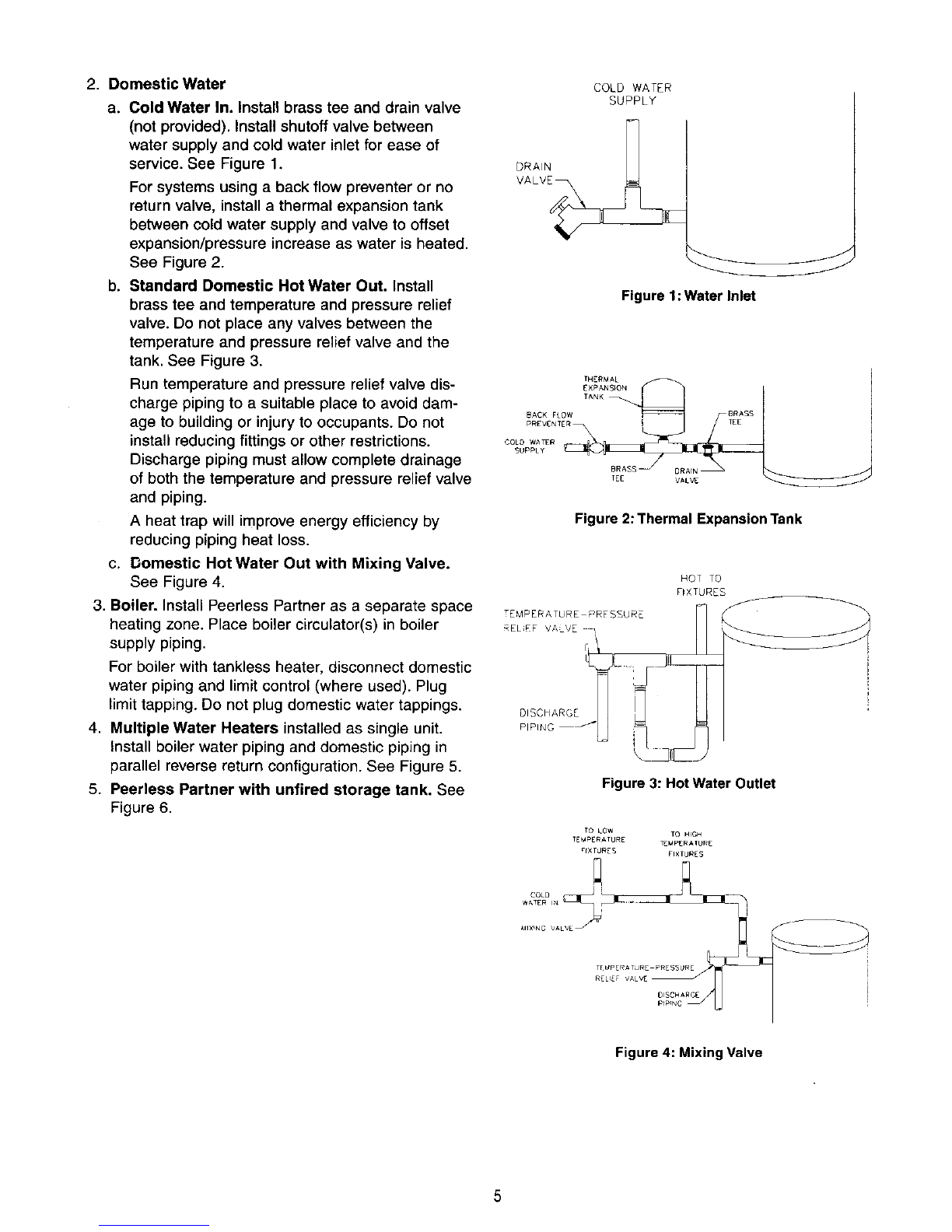
1. General
a. All plumbing must be in accordance with
the requirements of the authority having
jurisdiction.
b. Use both thread tape and pipe dope on all
mechanical connections.
c. Zone valve (if used) and circulator must be
sized to provide minimum flow rate speci-
fied in Table 4. Use 1 inch nominal copper
tubing between boiler and Peerless Partner
heat exchanger. See Table 5 and Table 6 for
sizing. Point of emphasis: using a zone
valve without a full bore may cause high
pressure drop which will adversely affect
performance. Use extreme care when
selecting zone valve.
All piping must be adequately supported.
Allow for thermal expansion.
d. High temperatures will damage plastic jack-
et. Use heat shield when soldering piping
near tank.
Table 4: Flow Specifications
Model
No,
PP-40
PP-60
PP-80
PP-120
PP-40-DW
PP-60-DW
PP-80-DW
PP-120-DW
Recommended
FlowRate
10 gpm
10 gpm
12 gprn
14 gpm
6 gpm
7 gpm
7 gpm
8 gpm
HeatExchanger
PressureDrop
7.9 ft.
7.9 ft.
9.1 ft.
11.3 ft.
7.6 ft.
10.0 ft.
10.0 ft.
13.4 ft
DomesticWater
ConnectionSizes
3/4 NPT
1 NPT
1-1/2 NPT
1-1/2 NPT
3/4 NPT
1 NPT
1-1/2 NPT
1-1/2 NPT
Table 5: Friction Loss
TubingType
Type K
Type L
Type M
)er 100 Feet of Tubing [feet]
FlowRate[gpm]
6710
3.6 4.8 9.3
3.1 4.1 8.1
2.7 3.6 7.0
Table 6: Friction Loss Allowance for Copper Fittings
[feet of straight tubing]
Fitting Wrought Cast
90° Elbow 1 4
45° Elbow 1 2
Tee, Run V2 V2
Tee, Branch 3 5
90° Bend 2 --
180° Bend 2 --
Gate Valve -- 1

2. Domestic Water
a. Cold Water In. Install brass tee and drain valve
(not provided). Install shutoff valve between
water supply and cold water inlet for ease of
service. See Figure 1.
For systems using a back flow preventer or no
return valve, install a thermal expansion tank
between cold water supply and valve to offset
expansion/pressure increase as water is heated.
See Figure 2.
b. Standard Domestic Hot Water Out. Install
brass tee and temperature and pressure relief
valve. Do not place any valves between the
temperature and pressure relief valve and the
tank. See Figure 3.
Run temperature and pressure relief valve dis-
charge piping to a suitable place to avoid dam-
age to building or injury to occupants. Do not
install reducing fittings or other restrictions.
Discharge piping must allow complete drainage
of both the temperature and pressure relief valve
and piping.
A heat trap will improve energy efficiency by
reducing piping heat loss.
c. Domestic Hot Water Out with Mixing Valve.
See Figure 4.
3. Boiler. Install Peerless Partner as a separate space
heating zone. Place boiler circulator(s) in boiler
supply piping.
For boiler with tankless heater, disconnect domestic
water piping and limit control (where used). Plug
limit tapping. Do not plug domestic water tappings.
4. Multiple Water Heaters installed as single unit.
Install boiler water piping and domestic piping in
parallel reverse return configuration. See Figure 5.
5. Peerless Partner with unfired storage tank. See
Figure 6.
COLD WATER
SUPPLY
Figure 1: Water Inlet
THERMAL
EXPANS_ON
TANK
BACK FLOW BRASS
pREVENTER I TEE
COLD WA_R _
SUpPLy
BRASS
Figure 2: Thermal Expansion Tank
TEMPERATURE PRFSSURE
RELEF VALVE ]
HOT TO
FIXTURES
Figure 3: Hot Water Outlet
TO LOW TO HIGH
TEmPErATURE TEMPERATUR E
rr×TURES FIXTURES
Figure 4: Mixing Valve
5

T & P RELIEF
VALVE
U
NOT T& P RELIEF HOT T & P RELIEF HOT
ouT;vALvE ouvA
TAT TAT TAT
..... L ... I ........................ J
__i II I - I Ii I J
COLO__l [ It
_ATER [
SUPPLY
NOTE: ALL PIPLNG IN PARALLEL
Figure 5: Installation of Multiple Water Heaters as Single Unit
HOT WATER
I TO FIXTURES
HOT WATER
fO
FIXTURES
T & P RELIEF <
VALV£
tOLD
WATER
_UPPLy
T & P RELIEF
VALV£
PEERLESS
PARTNER
_NK CONTROL NO
VALVE
TANK _
ORCUt_.TOR
801tER /_
CONTROL.
801LER RETURN
BOILER
CIRCU_TOR
Figure 6: Unfired Storage Tank
1. The Peerless Partner must be electrically grounded in accordance with local codes. In the absence of local
codes follow the National Electrical Code, ANSI/NFPA 70.
2. Install thermostat provided with Peerless Partner. Insert bulb into immersion well. Secure to well by tightening
screws on case.
3. Wire Peerless Partner thermostat to boiler. Provide disconnect switch between thermostat and control system
to allow for vacation shutdown and/or service shutdown.
Zoning with zone valves assumes end switch is isolated - zone valve actuator powered by separate
transformer. Do not use boiler transformer to operate zone valves.
a. MI/MIH. For zoning with zone valves or three-way valve, connect zone valve end switch to limit terminals T
and TV. For zoning with circulators, refer to Figure 7.
b. DE/PSC/PDE. Provide zone control as shown in boiler's installation instructions.
d. WBV/EC/SC. Water less tankless heater. See Figure 8.
6

TO P((_(_ SNT_T_C F_LAY
p_IT_R I_4(R'W_TAT H_ _194_A
TO _(_tESS
p_t_R C_I_LA T_
LOW _OLTAd:_
TO_l
_m_S,AT
I I
II
I I
i I
ii
I i I
I i L---_
ro e_w.(R
C_L_IC_
Figure 7: Wiring Diagram - MI/MIH
TO PEERt£SS
pARTNER ORCULATOe
TO PEERLESS
p_Rm£R _ERMOSTAT i--S_TCH_NG R£LAY
JHO_E_LL R845A TO ZC_E I
I I _1TE ROOC[_S 829A 845 SPACE _EA_N_
I I /_RUOST_T
D_SC_NECT
I I
F1__
______ ®
...... A. B_ONL_E_'_]TL_148A _ t t t t
-- --LOW VOLT_G_ TO B<MLER TO BURNER
Figure 8: Wiring Diagram -WBV, EC and SC less Tankless
1. General
a. Open hot water faucet when filling or draining Peerless Partner.
b. The Peerless Partner thermostat has three markings: Warm (120°F), Normal (140°F), and Hot (160°F).
The thermostat is adjusted to its lowest temperature position when shipped from the factory.
2. Fill tank and domestic water piping.
3. Adjust Peerless Partner thermostat to 119°F, or in accordance with authority having jurisdiction. Adjust
mixing valve (if used) to desired temperature.
I._'6 r
j--v IWater temperatures over 125°F can cause severe burns instantly, or
death from scalds.
Children, disabled, and elderly are at the highest risk of being scalded.
See instruction manual before setting temperature at water heater.
Feel water before bathing or showering.
Temperature limiting valves are available, see manual.
4. Follow manufacturer's instructions to start-up boiler. Set boiler limitat least 20°F above Peerless Partner
thermostat setting. For boiler limit with low limit, set temperature to lowest setting. For boiler limits with
adjustable differential, set differential tO 10-15°F range.
5. Operate boiler until Peerless Partner thermostat satisfied. Measure domestic water temperature at hot
water faucet. See Paragraph 3 above.
6. Draw hot water and allow Peerless Partner to operate through several recovery cycles to verify proper
operation.

1. General Housekeeping (continuous). Keep area clear of gasoline or other flammable vapors or liquids.
Controls on this appliance could ignite vapors causing an explosion.
2. Clean Inside of Tank (monthly).
a. Mark temperature setting on Peerless Partner thermostat. Set thermostat to lowest setting.
b. Close cold water inlet shutoff valve. Open a hot water faucet,
c. Open drain valve. Allow water to flow until free of sediment. Close drain valve.
d. Open cold water inlet shutoff valve. Close hot water faucet after flow established.
e. Set Peerless Partner thermostat to operating set point.
3. Check temperature and pressure relief valve. Follow manufacturer's instructions.
4. Maintain boiler per manufacturer's instructions.
1. No Hot Water
a. No power to boiler and control system.
* Check fuse or circuit breaker.
* Check disconnect switch.
* Check wiring.
b. Zone Valve is not open.
* Check wiring.
* Repair or replace zone valve.
C. Circulator is not operating.
* Check wiring.
* Check circulator switching relay.
* Repair or replace circulator.
d. Peerless Partner thermostat not calling for heat.
* Check wiring.
* Replace thermostat.
e. Hot water from boiler not getting to Peerless Partner.
* Air trapped in boiler piping, preventing water circulation. Purge piping.
* Check boiler for proper operation.
* Check wiring.
2. Inadequate Hot Water
a. Check operation of Peerless Partner:
i. Obtain container with known volume (in gallons) and stopwatch.
ii. Open hot water faucet until boiler starts recovery period. Close faucet.
iii. Allow boiler to operate until water heater fully recovers. Set thermostat disconnect switch to OFF
position.
iv. Open hot water faucet until water is hot. Begin filling container. Use stopwatch to measure time to fill
container.
Container Volume (gallons) seconds
Flow Rate (gpm) = x 60
Time to Fill Container (seconds) minute

v. Water temperature will remain constant within ±5°F until storage is exhausted. Continue to fill container
until temperature drops 10°E
vi. Compare total volume of water collected to Usable Hot Water in Table 1. If within 5 gallons the Peerless
Partner is operating properly. Check PRODUCT SELECTION for proper model usage.
vii. Compare calculated flow rate with first draw usage available per Table 3. If actual flow rate is greater
than first draw usage available, consider use of flow restricting fixtures or mixing valve.
b. Inadequate boiler water flow. Check circulator sizing per PIPING.
c. Boiler is undersized.
3. Slow Recovery.
See 2(b)(c) above. Approximate cold start recovery period (* use Minimum Boiler Output from Table 1 or
Boiler Rated Output, whichever is smaller):
Recovery Time [Minutes) -
Btu
Tank Capacity [gallons] x Temperature Rise [°F] x 8.33(gallons)(°F)
Btu .
Boiler Output hr
minutes
x 60 hr
Example No.l: A Peerless Partner PP-40 with a Peerless MI-03 gas boiler (DOE Heating Capacity of 58 Mbh).
The desired water temperature is 115°E Cold water temperature is 55°E
Btu
(37 gallons) x (115°F-55°F) x 8.33
Recovery time = (gall°ns)(°F) x 60 minutes
Btu hr
58,000 -- hr
19.1 minutes
Example No. 2: A Peerless Partner PP-120 with a Peerless LC-04 (Gross I=B=R Output of 547 Mbh). The
desired water temperature is 150°E Cold water temperature is 50°E
Btu
(119 gallons) x (150°F-50°F) x 8.33
Recovery time = (gall°ns)(°F) x 60 minutes
Btu hr
300,000 --hr
19.8 minutes
4. WaterTemperatureToe Hot
a. Peerless Partner thermostat set too high. Adjust to lower setting.
b. System piping and/or controls.
* Peerless Partner thermostat continues to call for heat after reaching setpoint. Replace thermostat.
* Check system piping and flow control valve.Verify space heating call for heat does not cause flow through Peerless
Partner heat exchanger.
C. Mixing Valve (if used). Verify proper operation per manufacturer's instructions.
5. Leaking Temperature and Pressure Relief Valve
a. Water expands when heated.
* Install thermal expansion tank on cold water inlet.
* Reduce Peerless Partner thermostat setting.
b. Water temperature too high. See Paragraph 4 above.
c. Water pressure is too high. Instafl pressure reducing valve on cold water inlet.
d. Valve seat has deteriorated or has sediment build-up. Replace temperature and pressure refief valve.

Hot Water Cutlet,
T&P Relief Valve
2_"Polyurethane Foam
Insulation On Outside,
Less Than 1/2°F Per
Hour Heat LOSS R 17
-- 316L Stainless Steel Tank
-- Plastic Jacket
Domestic Water
Connections (See
Dimensional Data) I
Enclosed Thermostat Weft for
Adjustable Honeywell Control
Cold Water
Inlet & Drain
(Boiler Water Supply
& Return 1" Threaded)
Boiler Supply
Cupronickel
Coil Assembly
Boiler Return
FLOOR
Figure 9: Cutaway View
Table 7: Dimensions and Specifications
Model
No,
PP-40
PP-60
PP-80
PP-120
PP-40-DW
PP-60-DW
PP-80-DW
PP-120-DW
Diameter Height
191/4 521/2
231/4 521/2
24 72
27 731/2
191/4 521/2
231/4 521/2
24 72
27 731/2
Dimensions[inches]
Floorto Floorto
'Boiler In' 'Boiler Out'
9 41/2
9 41/2
29 6
301/4 71/4
9 41/2
9 41/2
29 6
301/4 71/4
Floorto
'Cold-Drain'
3
3
6
7i14
3
3
6
7V4
Floorto
'Hot-T&P'
46
46
66
66
46
46
66
66
Pressures
[psig]
Test
300
300
300
300
300
300
30O
300
Working
150
150
150
150
150
150
150
150
Tank
Capacity
[U.S.
Gallons]
37
57
77
119
37
57
77
119
Thermostat: Honeywell L4080B1295 (Operating range = 120°F to 160°F, 15°fixed differential)
Temperature and Pressure Relief Valve: PP-40: Watts 100XL-8 (100 Mbh, 8" element)
PP-60/80/120: Watts 40XL-8 (200 Mbh, 8" element)
10

Peerless ®Partner ®
Indirect-Fired Water Heater
Installation,
Operation
Maintenance
Manual
TO THE INSTALLER:
This manual is the property of the owner and
must be affixed near the water heater for
future reference.
TO THE OWNER:
This water heater should be inspected annually
by a Qualified Service Agency.
PEERLESS"
PARTNER °
INDIRECT FIRED WATER HEATER
PEERLESS HEATER COMPANY
231 NORTH WALNUT STREET•BOYERTOWN, PA 19512-1021 •PHONE 610-367 2t53
vvww.peedess heater.corn
THE PREFERRED HEATING CHOICE
@2002 Peerless Heater Company X8033 R4 (11/02 3M)
Printed in USA
This manual suits for next models
3
Table of contents
Other PEERLESS Water Heater manuals
Popular Water Heater manuals by other brands

Schier
Schier GB-1000 installation guide

UK CYLINDERS
UK CYLINDERS 175006 installation manual

Rittal
Rittal SK 3216.480 Assembly instructions

Riello
Riello Array AR 399 SE Installation, operation and service manual

Bock Water heaters
Bock Water heaters SideKick 30SK instruction manual

MEGAFLO
MEGAFLO 400L Product guide

Haier
Haier FCD-JTHC100A-III (E) user manual

Heatworks
Heatworks MODEL 3 User manual & installation guide

Adventure Kings
Adventure Kings AKHWS01 user manual

Kenmore
Kenmore POWER MISER 9 153.337163 owner's manual

Ariston
Ariston VELIS TECH PW ABSE 80 Assembly and operation instructions

Ruud
Ruud Tankless Indoor RUTG-53PV Specification sheet