4
E. PRODUCT SELECTION
1. The following guidelines apply to residential systems
only. For commercial or institutional installations
contact your local PB Heat, LLC representative.
2. Determine the quantity of domestic hot water
required. Factors to consider:
a. Estimate typical peak hour demand. Determine
the general time of day (morning, noon, evening)
when the most hot water is used. Use chart below
to determine potential maximum usage.
b. Estimate unusual peak draw demand.
Whirlpool baths, hot tubs, and multiple head
showers require large quantities of hot water in a
short period of time. Contact fixture manufacturer
for quantity of water required. Generally speaking,
these circumstances can only be met with larger
storage volumes.
c. Domestic Water Temperature. Most residential
usage will be satisfied with 119°F water, the
temperature setting recommended by the
Consumer Product Safety Commission. Some
applications such as laundry and dishwashers may
require a higher temperature.
Ratings can be improved by increasing Peerless®
Partner®thermostat setting and using a mixing
valve to temper the hot water to the proper
temperature. When temperatures greater than
119°F are required, use a mixing valve at the
outlet of the water heater or anti-scald fittings at
point of use.
d. Domestic water priority. First hour ratings may
be less than published when boiler output is
shared with space heating. Generally a consumer
will notice a drop in domestic water temperature
before a drop in space heating temperature.
Giving domestic water production priority by
directing entire boiler output to Peerless®Partner®
will maximize domestic water output. However,
prioritization controls could result in an
unacceptable drop in space heating temperature
when large quantities of domestic hot water are
used, and a prioritization control malfunction
could result in loss of space heating.
3. Multiple Water Heaters. Peak domestic water
usage (first hour rating) or unusual peak draw may
not be met with a single water heater. Multiple units
can be installed as either a bank of tanks acting as a
single unit, or as multiple individual units sized and
located for specific draw situations.
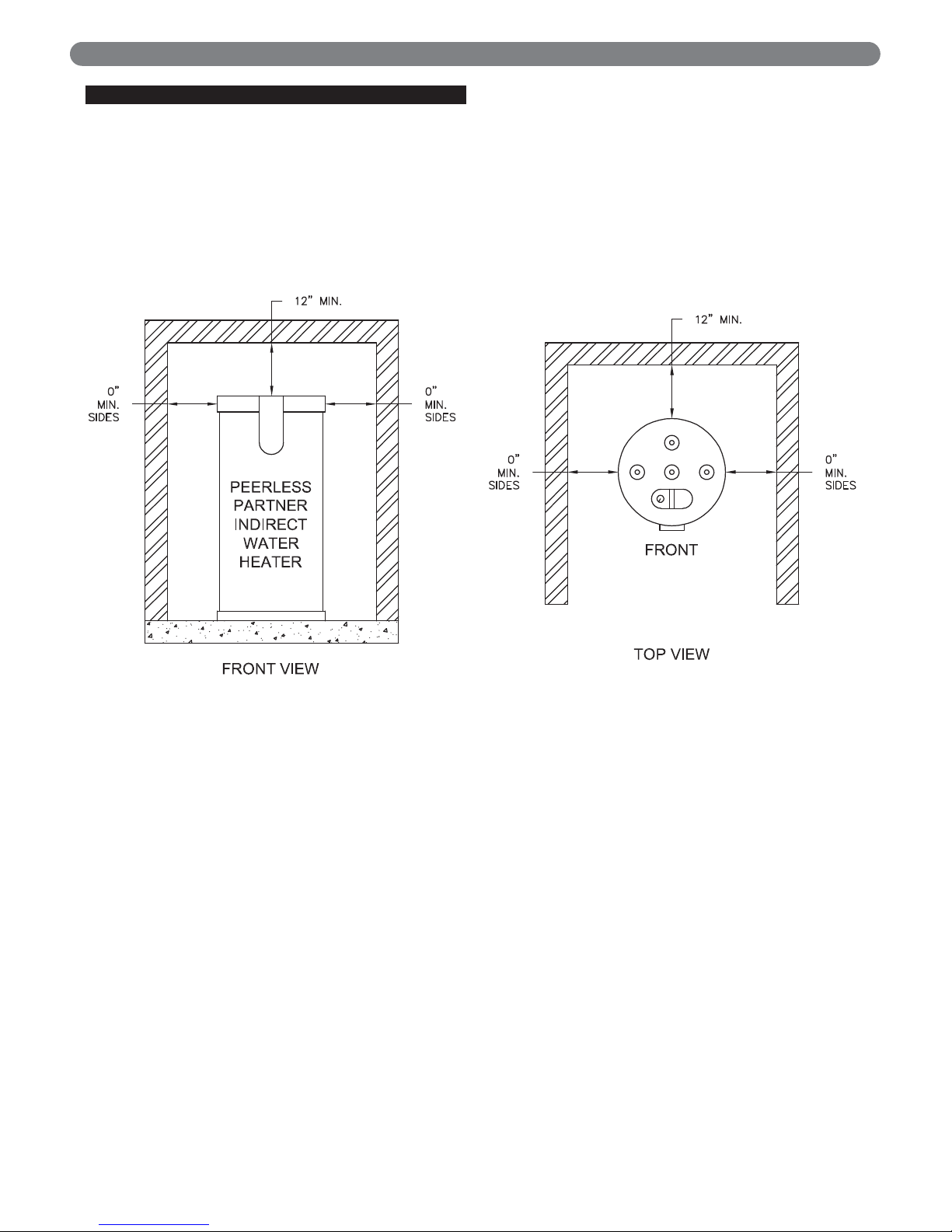
PREINSTALLATION
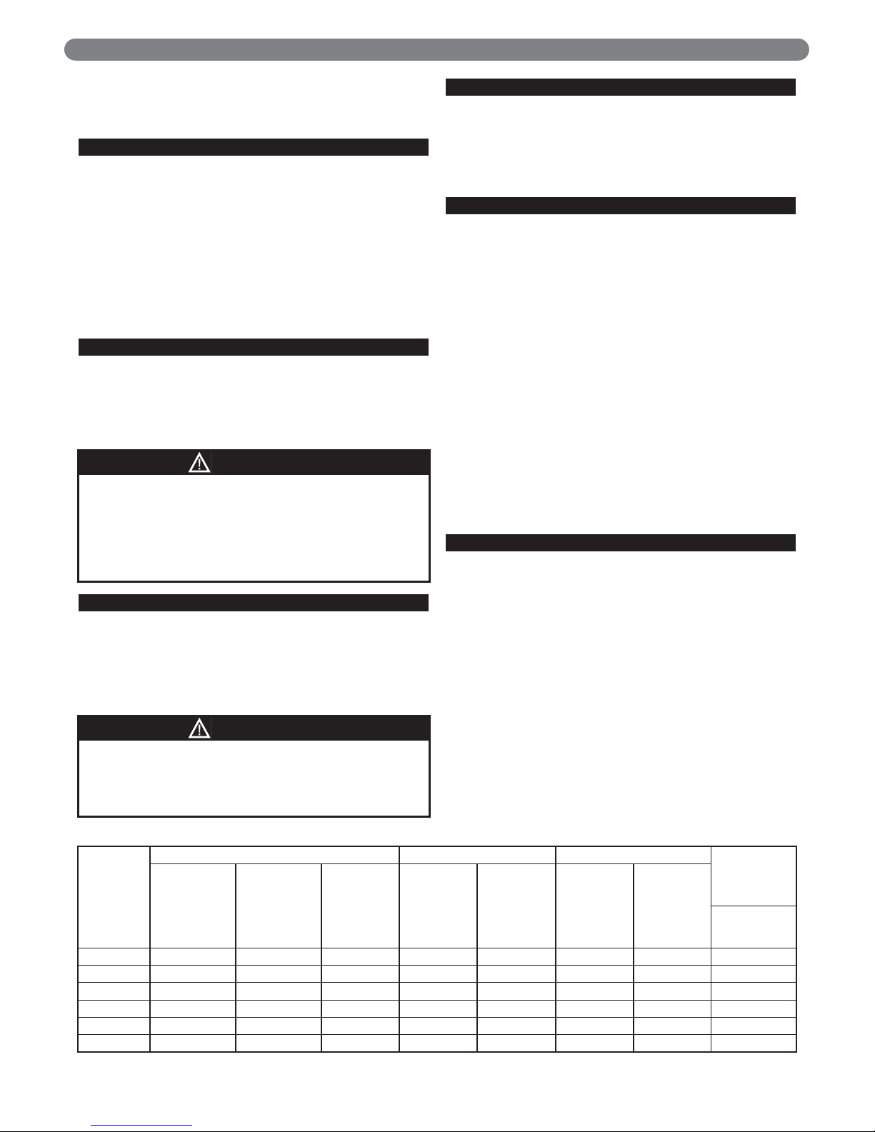
Estimate of Peak Domestic Hot Water Usage
Average Gallons of Times Used During Gallons Used in
Use Hot Water per Usage One Hour One Hour
Shower 20 x _____________ = _____________
Bath 20 x _____________ = _____________
Shaving 2 x _____________ = _____________
Hands and Face Washing 4 x _____________ = _____________
Hair Shampoo 4 x _____________ = _____________
Hand Dish Washing 4 x _____________ = _____________
Automatic Dish Washing 14 x _____________ = _____________
Food Preparation 5 x _____________ = _____________
Wringer Clothes Washer 26 x _____________ = _____________
Automatic Clothes Washer 32 x _____________ =
Total Peak Hour Demand = __________
The Peerless®Partner®indirect-fired water heater is
deemed to be used in a "commercial setting" if at
any time the unit is operated at a temperature over
150°F. Refer to warranty for additional information.
NOTICE
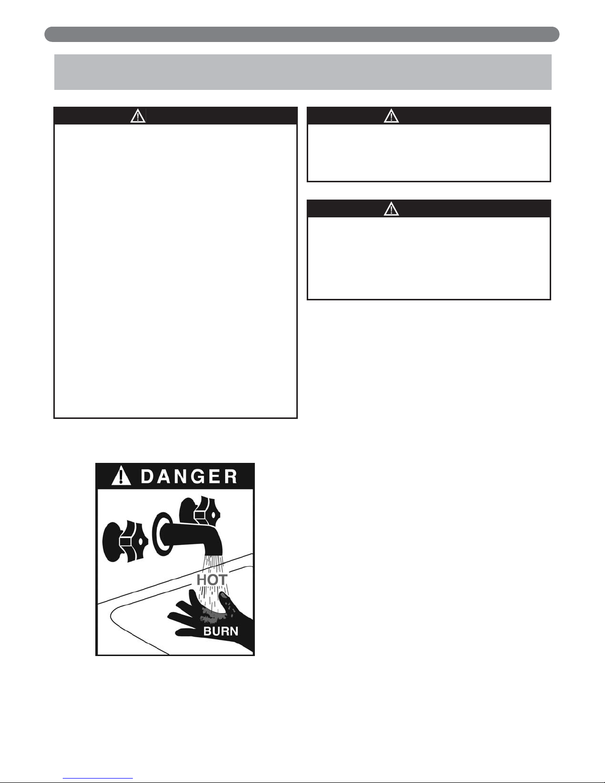
DANGER
Water temperatures over 125°F
can cause severe burns instantly,
or death from scalds.
Children, disabled, and elderly are
at the highest risk of being
scalded.
See instruction manual before
setting temperature at water
heater.
Feel water before bathing or showering.
Temperature limiting valves are available, see
manual.


 Operation and maintenance instructions")