17
8. Device Maintenance
Only the personnel who have studied the operations manual and have been trained to safely
operate the device should be allowed to maintain the device.
A heavy daily beer ow through the PEGAS Evolution may eventually clog the beer supply ele-
ments, as well as the drain and throttle parts, and hoses.
In order to avoid the clogging and fouling of device elements, the dispenser should be washed
and disinfected regularly.
Washing
To clean the device a sanitary liquid should be supplied from a hose-adapted container placed
at the beer keg position. The beer supply hose and the PEGAS Evolution device itself are the
rst ones to be washed. In order to wash the drain hose, a plastic bottle should be placed into
the down-hold mechanism. When the plastic bottle overows, the drain and throttle elements
are clean.
PEGAS Evolution Sanitary Standards
Sanitary Rules for the Brewing and Beverage Industry (СП) 3244-85* stipulate that dispensing
devices should be washed daily for 30 minutes both in hot (60°C) and cold water.
Weekly disinfection of the device (using Antiformin, Sulfochlorantin, Benzalkonium Chloride dis-
infectants) and a thorough rinse with water until the full dissolution of the disinfecting agent has
been reached is required.
* This standarts is currently in effect in the territory of the Russian Federation. Maintenance of the device should be done according
to the schemes described by Chart 1.
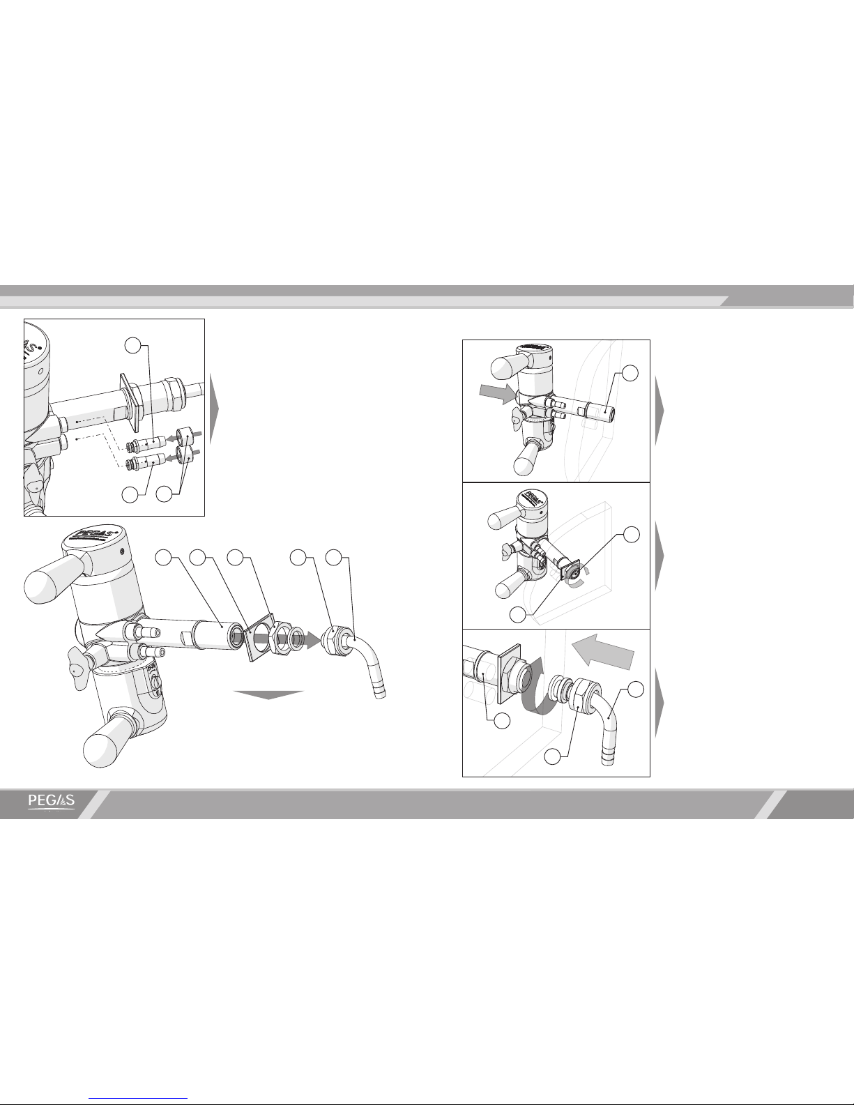
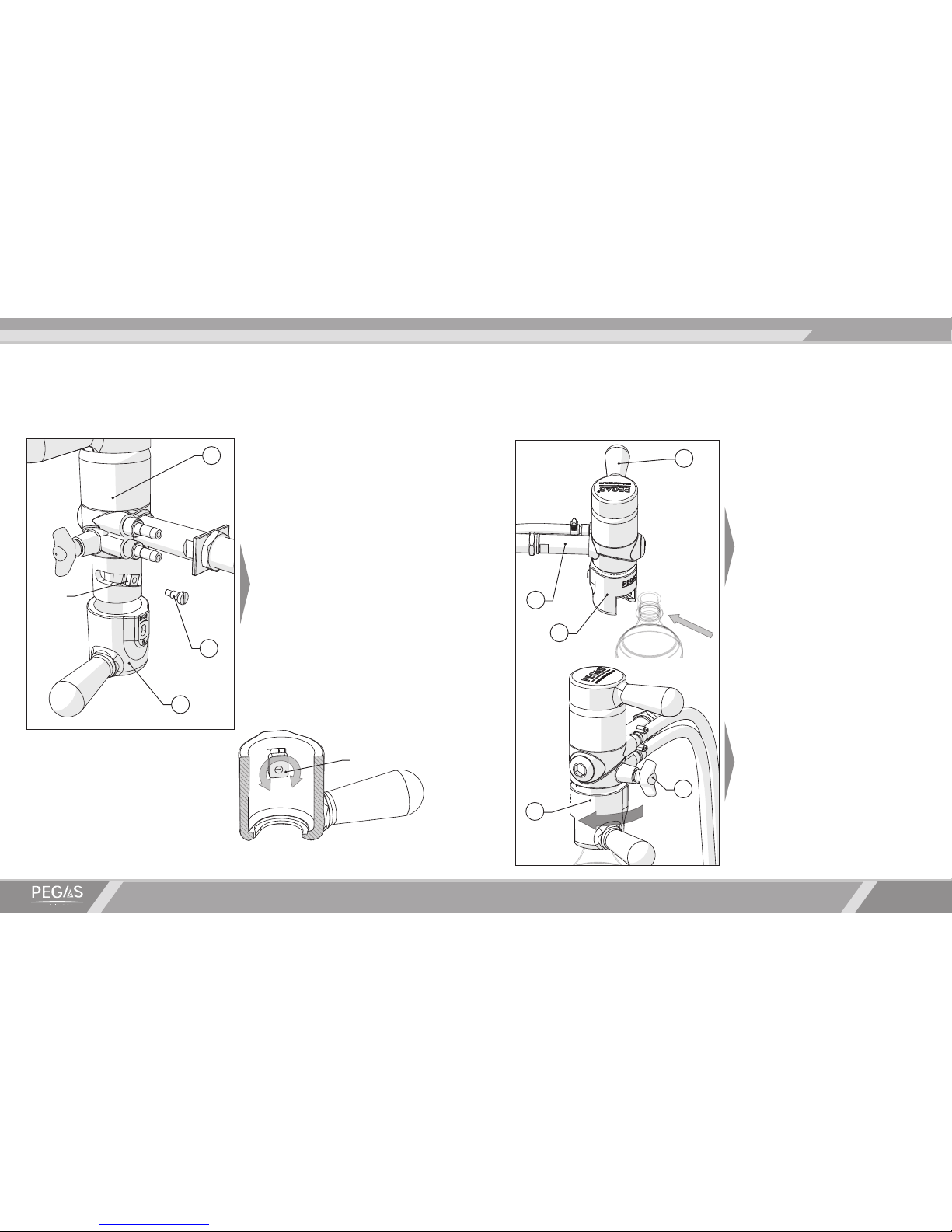
Sanitary procedures:
•Disconnect the beer keg from the beer supply system.
•Prepare a container for collecting used used water/cleaning agent.
•Make sure that the changeover valve handle is in its middle position.
•Connect the beer dispensing system to the source of water/cleaning agent.
•Place an empty plastic bottle (preferably of small capacity) into the universal bottle holder; fasten
it by turning the bottle holder lever to the left.
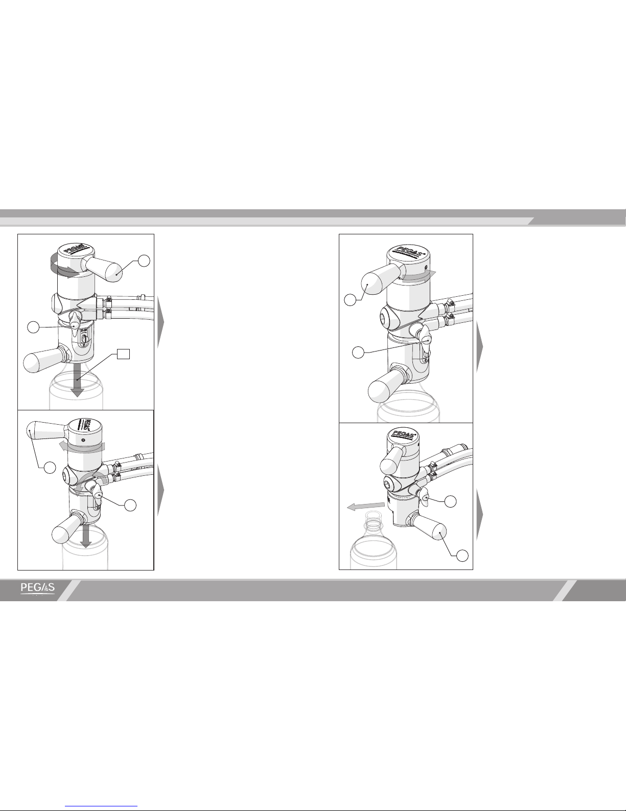
•Open the throttle valve.
•Pull the switch valve handle until it stops.
• Make sure to control the rate of ll as it can overow rapidly. Be prepared to collect any excess
solution from the drain hose.
•Sanitary procedures should be implemented according to time frames prescribed by the chart.
•In order to stop the supply of water/cleaning agent, turn the switch valve handle to its neutral
position.
•Remove the bottle from the device.
•Use a clean cloth to remove the remaining water/cleaning agent from the surface of the PEGAS
Evolution device.
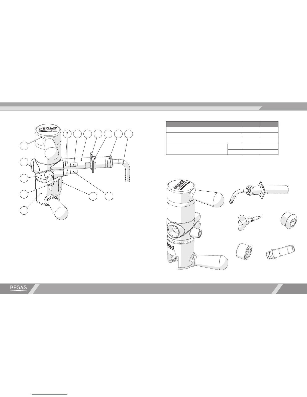
Type of
sanitary
procedure
Frequency Cleaning agent Time,
min. t0, C
Source of
cleaning
agent
Washing Every day after
use
Water 10 20 Water pipe
Rinsing Water 15 70-85 Water pipe
Disinfection Weekly
Lerades C 178 or similar
agents used in food
processing equipment
disinfection
10-15 60
Container
with a proper
tting
(wash-keg)
Rinsing After each
disinfection
Water 10 40-60 Water pipe
Rinsing Water 15 20 Water pipe
Sanitary and hygienic measures:
Chart 1