Pelican TC1 User manual

!
Before you start
Review all instructions before starting to avoid discovering or creating any
issues during installation. This thermostat is designed to be installed on 24
VAC systems only.
This thermostat is designed to be installed by a licensed professional.
A Pelican Gateway must be used with this thermostat. The thermostat cannot
be configured or managed without the gateway. We recommend installing
the gateway prior to installing this product.
Installation location
NEVER INSTALL IN AN ENCLOSED METAL BOX OR ON A METAL SURFACE.
Install in a location where it can communicate with the Pelican wireless mesh
network.
Install 48" to 60" from the floor in the room where it will be maintaining the
temperature.
Install on an interior wall away from doors, filing cabinets, electrical
equipment, or other metal objects.
Commercial Connected Thermostat
Installation Guide
PELICAN
Model: TC1

ON
OFF
Turn off the power to the equipment
this thermostat is going to be wired to.
Either turn off power at the circuit
breaker panel or by turning off the
master power.
Replacing an existing wired thermostat
Remove the cover from the old
thermostat and either take a picture
or label the wires as a guide for wiring
the new Pelican thermostat.
Uninstall the old thermostat and set
aside.
Installing a Pelican thermostat in a new location
This Pelican thermostat is designed to
either mount flush on the wall or on a
vertical 1-gang electrical box.
Choose a mounting location where
the thermostat:
is at least 48" to 60" above the floor.
is on an interior wall.
where it can detect the temperature
of the room it will be maintaining.
and is away from sun exposure or
airflow drafts.
Turn Off power
2

Install the thermostat back plate
Use the included screws to attach the thermostat to the
wall following one of the examples below:
Feed thermostat wire
through opening on back
plate.
Limited Wires? No Common Wire?
Follow pages 4 - 5 for limited wire instructions.
Follow pages 8 – 15 for common
thermostat wiring guides.
Connect wires to thermostat
3
electrical box installation wall installation
Use provided machine screws.
Drill two 3/16" holes (if using drywall
anchors).
Install provided drywall
anchors (if required).
Use provided sheet metal screws.
Vertical electrical
box.

4
Some installations have limited wires
between the thermostat and the HVAC
equipment. The included Wiring
Module can be used to control the
HVAC equipment without having to
run new or additional wires to the
thermostat.
This installation requires at least three
(3) wires between the thermostat and
the Wiring Module (unshielded wire is
okay).
This accommodates a maximum wire
distance of 500 feet between the
Wiring Module and the thermostat.
Step 1: Remove the Wiring Module
from the thermostat’s back plate.
Loosen the (R), (C), and (D) terminals
on the Wiring Module. Gently slide
the Wiring Module upwards (away
from the three pin connector) to
remove.
Step 2: Install the Wiring Module in
the HVAC equipment.
Locate the HVAC equipment’s
control board. Using new wire,
connect the Wiring Module’s
terminals to the corresponding
low-voltage input terminals on the
HVAC control board.
Follow the wiring diagrams from
Pages 8 – 15.
HVAC Control Board
Wiring Module
Wiring Module
Loosen
terminals.
Three pin
connector
Y2
W2
G
W
Y
R
C
Limited Wire Installation
Use a sheet metal
screw to secure the
Wiring Module.

5
Step 3: Connect Wiring Module to thermostat.
Use the existing wires from the Wiring Module to where the thermostat is
installed to connect the (R), (C), and (D) terminals from the Wiring Module to
the matching (R), (C), and (D) terminals at the thermostat’s back plate.
HVAC Control Board
Wiring Module mounted at control board.
Thermostat back plate mounted in room.
Y2
W2
G
W
Y
R
C
Maximum 500'. We recommend
unshielded 18 gauge thermostat
wire.

6
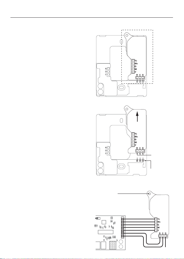
there are three (3) alignment
pins found on the left and right
sides of the base plate.
Attach the display
Before attaching the display, write
down the serial number on the screen
for use when configuring the
thermostat.
Align the display with the back plate’s
alignment pins. Press into back plate
until it clicks into place.
Switch on the power to the HVAC
equipment the thermostat is wired to.
If your Pelican thermostat does not
power on, see page 16 for assistance.
See page 17 for instructions on setting
the thermostat for Conventional or Heat
Pump control.
Optional: Tamper Resistant Lock
The thermostat contains an internal
locking mechanism to secure the display
to the back plate. This is intended to keep
unauthorized individuals from tampering
with the power and thermostat wire.
To engage the lock, assemble the
thermostat and insert a 1/8" flat head
screwdriver into the hole on the left side
of the thermostat. Push in slightly and
rotate 1/4 turn clockwise until reaching
the stop. Remove the screwdriver from
the hole.
To disengage, insert a 1/8" flat head
screwdriver into the hole on the left side
of the thermostat. Rotate 1/4 turn
counter-clockwise until reaching the stop.
Remove the screwdriver from the hole.
Do NOT force the display from the back
plate otherwise damage may occur.

7
DATA
COMMON
24 VAC POWER
COOL STAGE 1
HEAT STAGE 1
FAN
HEAT STAGE 2
COOL STAGE 2
D
C
R
Y
W
G
W2
Y2
DATA
COMMON
24 VAC POWER
COMPRESSOR STAGE 1
REVERSING VALVE (O/b)
FAN
AUXILIARY HEAT
COMPRESSOR STAGE 2
D
C
R
Y
W
G
W2
Y2
Conventional
DATA
COMMON
24 VAC POWER
VALVE OPEN
UNUSED
FAN
AUXILIARY HEAT
VALVE CLOSE
D
C
R
Y
W
G
W2
Y2
Two-Pipe Fan Coil
DATA
COMMON
24 VAC POWER
CHILLED VALVE OPEN
HOT VALVE OPEN
FAN
HOT VALVE CLOSE
CHILLED VALVE CLOSE
D
C
R
Y
W
G
W2
Y2
Four-Pipe Fan Coil
Heat Pump
Wiring Guides
For conventional heating and cooling systems, see pages 8 - 9
For heat pumps, see pages 10 - 11
For two-pipe fan coils, see pages 12 - 13
For four-pipe fan coils, see pages 14 - 15
For zone damper control, see separate installation guide Zone Damper Control.
For installations that are outside of this installation guide, STOP INSTALLING
THE THERMOSTAT, and contact Pelican Sales Engineering Support for further
assistance at 888.512.0490.
24 VAC Terminal Block Designations

8
Conventional Heating and Cooling Systems
(Up to 2 stages each)
2nd Stage Cooling
2nd Stage Heating
Supply Fan
1st Stage Heating
1st Stage Cooling
24 VAC Common
24 VAC Power
Y2
W2
G
W
Y
C
R
1
2
3
3a
Notes can be found on page 16.

9
Conventional Heating and Cooling Systems
(Up to 1 stages cool, 2 stages heat, and 2 speed fan)
G2
W2
G
W
Y
C
R
High Speed Supply Fan
2nd Stage Heating
Low Speed Supply Fan
1st Stage Heating
1st Stage Cooling
24 VAC Common
24 VAC Power
Notes can be found on page 16.
1
2
3
3a

10
Heat Pump Systems
(Up to 2 stages each and Auxiliary/Emergency Heat)
Y2
W2
G
O/b
Y
C
R
2nd Stage Compressor
AUX/Emergency Heat
Supply Fan
Reversing Valve
1st Stage Compressor
24 VAC Common
24 VAC Power
Notes can be found on page 16.
1
2
3
3a

11
Heat Pump Systems
(Up to 1 stages each, 2 speed fan, and Auxiliary/Emergency Heat)
G2
W2
G
O/b
Y
C
R
High Speed Supply Fan
AUX/Emergency Heat
Low Speed Supply Fan
Reversing Valve
1st Stage Compressor
24 VAC Common
24 VAC Power
Notes can be found on page 16.
1
2
3
3a

12
Two-Pipe Fan Coils*
(Power-open/spring-return or floating water valve)
2
W2
G
W
1
C
R
Water Valve Close
AUX/Emergency Heat
Supply Fan
(Unused)
Water Valve Open
24 VAC Common
24 VAC Power
4
Notes can be found on page 16.
*Contact Pelican Technical Support for thermostat configuration assistance.
1
2
3
3a

13
Two-Pipe Fan Coils*
(Power-open/spring-return water valve and 2 speed fan)
G2
W2
G
W
1
C
R
High Speed Supply Fan
AUX/Emergency Heat
Low Speed Supply Fan
(Unused)
Water Valve Open
24 VAC Common
24 VAC Power
Notes can be found on page 16.
*Contact Pelican Technical Support for thermostat configuration assistance.
1
2
3
3a

14
Four-Pipe Fan Coils
(Power-open/spring-return or floating water valve*)
4
3
G
2
1
C
R
Chilled Water Valve Close
Hot Water/Steam Valve Close
Supply Fan
Hot Water/Steam Valve Open
Chilled Water Valve Open
24 VAC Common
24 VAC Power
4
Notes can be found on page 16.
*Contact Pelican Technical Support for thermostat configuration assistance.
1
2
3
3a

15
Four-Pipe Fan Coils
(Power-open/spring-return water valves and 2 speed fan)
G2
W2
G
W
1
C
R
High Speed Supply Fan
AUX/Emergency Heat
Low Speed Supply Fan
Hot Water/Steam Valve Open
Chilled Water Valve Open
24 VAC Common
24 VAC Power
Notes can be found on page 16.
1
2
3
3a

16
Troubleshooting
Connect to 24 VAC class 2 circuits only.
Latching relays are rated for 24 VAC @ 2 amps continuous load.
All wire to be installed by customer in accordance with local electrical
codes.
Use 18 gauge unshielded thermostat wire.
Only found for actuators that are 24 VAC floating type.
1
2
3
3a
4
If the Pelican thermostat does not power on, check the following:
1. Check that all wires are properly inserted into the terminal blocks at the thermostat and
at the HVAC equipment. Lightly pull on the wires to make sure they are not loose.
2. Use a multi-meter to ensure that 24 VAC power is being supplied by HVAC equipment. If
24 VAC is not found, check that the master power has been turned back on for the HVAC
equipment or verify that the HVAC electrical breaker has not tripped. If the breaker has
tripped contact a Licensed Professional to assist, otherwise damage can occur to the
equipment or you can get hurt.
3. Use a multi-meter to ensure that 24 VAC power is found at the thermostat. If 24 VAC
was not found, but is found at the HVAC equipment, check for loose or spliced wires.
3. If you used the Wiring Module, use a multi-meter to ensure that 24 VAC power is found
at the Wiring Module and the thermostat. Check that the (R), (C), and (D) wires are
properly connected between the Wiring Module and the thermostat.
If the thermostat still does not power on, contact Pelican technical support for further
assistance at 888.512.0490.
If the Pelican thermostat does not show up on the Pelican App, check the following:
1. Check the thermostat upper right hand corner.
If you see this symbol then the thermostat is unable to connect to your Pelican
Wireless Mesh Network.
• Finish installing all your other Pelican thermostats and/or devices.
• Verify your Pelican thermostat is not in a metal enclosure and that there are no metal
structures/objects surrounding it. Wireless can NOT communicate through metal.
2. If you see this symbol then the thermostat is connected to your Pelican Wireless
Mesh Network, but your Pelican Gateway is unable to reach the Internet.
• Check your Pelican Gateway to verify it is installed, powered on, and has Internet
connection.
If you are unable to get the thermostat to connect to the wireless mesh network or
Internet, contact Pelican technical support for further assistance at 888.512.0490.
Notes

17
Thermostat Info Page
If the Pelican thermostat does not power on, check the following:
1. Check that all wires are properly inserted into the terminal blocks at the thermostat and
at the HVAC equipment. Lightly pull on the wires to make sure they are not loose.
2. Use a multi-meter to ensure that 24 VAC power is being supplied by HVAC equipment. If
24 VAC is not found, check that the master power has been turned back on for the HVAC
equipment or verify that the HVAC electrical breaker has not tripped. If the breaker has
tripped contact a Licensed Professional to assist, otherwise damage can occur to the
equipment or you can get hurt.
3. Use a multi-meter to ensure that 24 VAC power is found at the thermostat. If 24 VAC
was not found, but is found at the HVAC equipment, check for loose or spliced wires.
3. If you used the Wiring Module, use a multi-meter to ensure that 24 VAC power is found
at the Wiring Module and the thermostat. Check that the (R), (C), and (D) wires are
properly connected between the Wiring Module and the thermostat.
If the thermostat still does not power on, contact Pelican technical support for further
assistance at 888.512.0490.
If the Pelican thermostat does not show up on the Pelican App, check the following:
1. Check the thermostat upper right hand corner.
If you see this symbol then the thermostat is unable to connect to your Pelican
Wireless Mesh Network.
• Finish installing all your other Pelican thermostats and/or devices.
• Verify your Pelican thermostat is not in a metal enclosure and that there are no metal
structures/objects surrounding it. Wireless can NOT communicate through metal.
2. If you see this symbol then the thermostat is connected to your Pelican Wireless
Mesh Network, but your Pelican Gateway is unable to reach the Internet.
• Check your Pelican Gateway to verify it is installed, powered on, and has Internet
connection.
If you are unable to get the thermostat to connect to the wireless mesh network or
Internet, contact Pelican technical support for further assistance at 888.512.0490.
To access the thermostat info, touch Touch to adjust and then press the icon in
the upper right hand corner of the screen.
Serial Number
Is the unique identifier for this thermostat. Correlate this number on the Pelican App to configure
and name this thermostat.
Thermostat Name:
This is a custom identifier for this thermostat. The thermostat is named using the Pelican App.
Configuration:
This identifies the thermostat’s current configuration and provides the ability to change this
configuration between Conventional and Heat Pump. This can also be accomplished through the
Pelican App where other thermostat configurations are found.
Model Number:
This is the model number of this thermostat.
Alarm Notifications:
If there are any icons in the upper right hand corner of the thermostat, the Info page will identify the
issue detected. Follow the troubleshooting guide on page 16 for assistance.
Thermostat Conventional/Heat Pump Configuration Page
Within the first 5 minutes after the thermostat was last powered On, the thermostat
will allows you to set it to Conventional or Heat Pump control. This can also be done
at anytime through the Pelican App.
To access the configuration page, select Touch to adjust and then press the icon in
the upper right hand corner of the screen.
Under Configuration, you will see the current control setting (default configuration is
Conventional).
To change the configuration, press the change button to the right of Configuration.
Then touch Conventional, Heat Pump (O), or Heat Pump (B) and press Save at the
bottom of the screen to set the new configuration.
If you do NOT want to change the thermostat’s configuration, press Cancel at the
bottom of the screen.

this page intentionally left blank

this page intentionally left blank

PELICAN
Website: www.pelicanwireless.com
Phone: 888.512.0490 TC1 37-2200 REV 03
Pelican Wireless Systems. All Rights Reserved.
Table of contents
Other Pelican Thermostat manuals
Popular Thermostat manuals by other brands

Pro1 Technologies
Pro1 Technologies T631-2 installation manual

Amana
Amana TSTATA4271GT owner's manual

Roth
Roth EnergyLogic Touchline Guidelines for the electrician

Honeywell
Honeywell TheraPro HR90 instruction manual

Danfoss
Danfoss TP5000 RF Si Installation and user instructions

AEG
AEG FTE 400 quick start guide