manuals.online logo
Brands
  1. Home
  2. •
  3. Brands
  4. •
  5. Penguin
  6. •
  7. Water Pump
  8. •
  9. Penguin P-HF Series Maintenance and service guide

Penguin P-HF Series Maintenance and service guide

Models:
P-7 1/2-HF
P-10-HF
P-15-HF
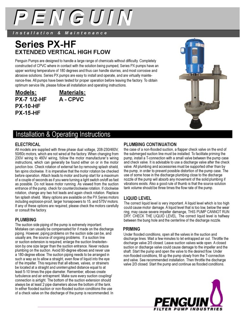
Penguin Pumps are designed to handle a large range of chemicals without difculty. Completely
constructed of CPVC where in contact with the solution being pumped, Series P-HF pumps have
an upper working temperature of 180 degrees and thus can handle slurries, and most corrosive
and abrasive solutions. Series P-HF pumps are easy to install and operate, and are virtually
maintenance-free. All pumps have been tested for proper operation before leaving the factory. To
obtain optimum service life, please follow all installation and operating instructions.
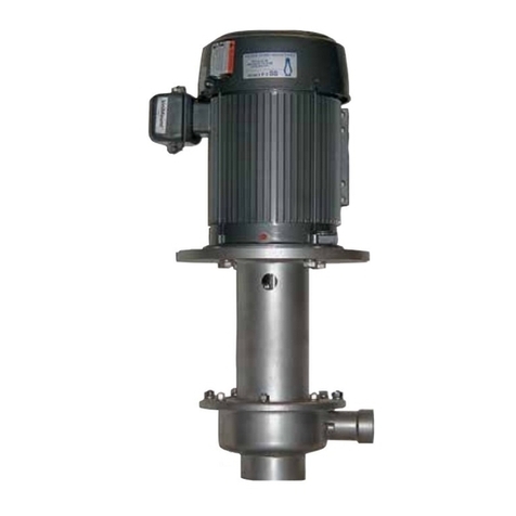
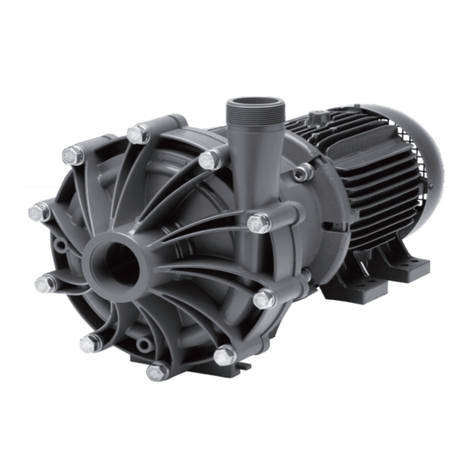
Model P-7 1/2-HF
Installation & Maintenance
PENGUIN
PENGUIN
Materials:
A - CPVC
Series P-HF
ELECTRICAL
PLUMBING
LIQUID LEVEL
PRIMING
The correct liquid level is very important. A liquid level which is too high
could cause motor damage. A liquid level that is too low, below the wear
ring, may cause severe impeller damange, THIS PUMP CANNOT RUN
DRY. CHECK THE LIQUID LEVEL. The correct liquid level is halfway
between the bung hole and the centerline of the discharge nozzle.
Under ooded conditions, open all the valves in the suction and
discharge lines. Wait a few minutes to let entrapped air out. Throttle the
discharge valve 2/3 closed. Leave suction valves wide open. A closed
suction or discharge valve could cause damage to the impeller and the
shaft. Start the pump and open the valve to the desired ow. Under
non-ooded conditions, ll up the pump slowly from the T-connection
and valve. See recommended installation. Then throttle the discharge
valve 2/3 closed. Start the pump and continue as ooded conditions.
Installation & Operating Instructions
PLUMBING CONTINUATION
HIGH FLOW VERTICAL PUMP
All models are supplied with three phase dual voltage, 208-230/460V,
50/60c motors, which are not wired at the factory. When changing from
230V wiring to 460V wiring, follow the motor manufacturers wiring instruc-
tions, which can generally be found either on or in the motor junction
box. Check rotation of external fan by removing splash shield, fan spins
clockwise. It is imperative that the motor rotation be checked before op-
eration. Attach leads to motor and bump start for a maximum of a couple
of seconds as if you were turning a light switch on/off as fast as possible.
Do not leave motor running. As viewed from the suction entrance of the
pump, check for counterclockwise rotation. If clockwise rotation, change
any two hot leads and again check rotation. Replace fan splash shield.
Many options are available on the P-HF Series motors including larger
horsepowers to 15 and 575V motors. If any of these options are required,
please check the motors carefully or consult the factory.
The suction side piping of the pump is extremely important. Mistakes
can usually be compensated for if made on the discharge piping.
However, piping problems on the suction side can be, and usually are,
the source of ongoing problems. If a suction line or suction extension
is required enlarge the suction line/extension by one size larger than
the suction entrance. Never reduce plumbing on the suction. Avoid
90-degree elbows and never use a 180-degree elbow. The suction
piping needs to be arranged in such a way as to allow a straight, even
ow of liquid into the eye of the impeller. This requires that all elbows,
valves, or strainers be located at a straight and uninterrupted distance
equal to at least 5-10 times the pipe diameter. Remember, elbows
create turbulence and air entrapment. Make sure every suction
coupling/connection is airtight. The bottom of the suction extension
should always be at least 2 pipe diameters above the bottom of the
tank. In either ooded suction or non-ooded suction conditions, the
use of a check valve on the discharge of the pump is recommended.
In the case of a non-ooded suction, a apper check valve on the end
of the submerged suction line must be installed. To facilitate priming the
pump, install a T-connection with a small valve between the pump case
and check valve. It is advisable to use a discharge valve after the check
valve. All plumbing and accessories must be supported other than by
the pump, in order to prevent possible distortion of the pump case. The
use of some hose in the discharge plumbing close to the discharge
nozzle of the pump will absorb any movement of the solid plumbing if
vibrations exists. Also a good rule of thumb is that the source solution
tank volume should be three times the ow rate of the pump.
Series P-HF_D_01-15
Recommended Installation
Suction Level
Suction Head
Recommended installation
for optimal performance
and endurance.
In Tank - Solution may pour out of weep hole during
operation
Out of tank - Solution will pour out of weep hole and
may ood motor when not in operation
Low Liquid Level
Non-ooded conditions. Pumps will not pump
Recommended
Recommended
Recommended
Liquid level halfway between discharge and
weep hole
Solution level below impeller. Pumps will not
pump
Solution level below impeller with priming tee.
Check valve and throttling valve
Solution level at impeller. No suction head
available Solution level above impeller. Suction head
available
KEY
Out-Of-Tank Installation
In-Tank Installation
Valve
Check Valve
Flapper Check Valve
High Liquid Level
Check valves installed to maintain level. Not
good to prime pumps
RECOMMENDATIONS
Always make sure there is enough liquid in the reservoir and that the level is high enough, considering the capacity of the pump unit. Inadequate liq-
uid will cause a vortex in the reservoir. A vortex occurs when air mixes from the surface into the uid, which can disturb the ow and can also prevent
the pump from priming. Therefore, a rule of thumb is to maintain a minimum of 2ft. of suction pipe submergence in order to prevent the formation of
vortices. Suction pipe velocities should not exceed 5ft/sec. In cases where the pump is installed outside the reservoir, do not run against a closed
discharge valve for more than 1 minute. This will cause overheating of the uid in the pump and will damage the CPVC parts. Temperature in this
case will increase up to 220 degrees. If the pump is being run against a closed discharge valve for a long duration of time, install a small bleed line
back into the reservoir before the discharge valve of the pump. If the line is small, there is a minimum pressure loss. This prevents overheating by
recirculating the uid.
Installation & Maintenance
PENGUIN
PENGUIN
Spare Parts List - P-7 1/2A-HF, P-10A-HF, P-15A -HF
19
2
11
2A
1
3
7
14
15
10
8
12
9
x
13
16
Item Description P-7 1/2A-HF P-10A-HF P-15A-HF
1
Motor/Shaft Ass’y
phase - volt - cycle
3 208-230/460 50/60
PHF-712-3103K PHF-1000-3103K PHF-1500-3103K
1BS Bearing Set PHF-712-01BS
1EF* External Fan w/Set Screw PHF-712-01EF
1FC* Fan Cover (w/Drip Shield) PHF-712-01FC
2 Motor Screw/Standoff Ass’y PHF-712-05(4)
3 V-Seal PHF-712-02
7A Pump Housing Ass’y -
CPVC PHF-712-06A
8Impeller - CPVC PHF-712-07AK PHF-1000-07AK PHF-1500-07AK
8V Impeller Sleeve O-Ring -
Viton PHF-712-07AV
8E Impeller Sleeve O-Ring -
EPR PHF-712-07AE
9V Head O-Ring -Viton PHF-712-11V
9E Head O-Ring -EPR PHF-712-11E
10 Head Ass’y - CPVC PHF-712-10A
11V Lip Seal Ass’y-Teon PHF-712-13T
12A Snap Ring - CPVC PHF-712-12A
13V Impeller Nut O-Ring - Viton PHF-712-08V
14A Impeller Nut Ass’y - CPVC PHF-712-09A
15T Shaft Key - Titanium PHF-712-15K
16A Snap Ring Bolts - CPVC PHF-712-16A(6)
18A Discharge Plumbing - CPVC PHF-712-18A
19A Pump Head Ass’y - CPVC PHF-712-14AK PHF-1000-14AK PHF-1500-14AK
* Specify Motor Manufacturer
P-7 1/2A-HF thru P-15A-HF
DISASSEMBLY
1. Unscrew and remove discharge piping. Remove the six (6) snap ring bolts (Item 16).
Now the snap ring (Item 12) can be removed using a screwdriver or a pair of pliers.
2. With a rubber mallet, gently hit the back of the suction casing (Item 10).
Alternating blows from one side to the other until the suction casing comes off.
Suction casing O-ring can easily be replaced.
3. Unscrew the impeller nut using a 3/4 inch socket wrench in a counterclockwise rotation.
Impeller nut O-ring can be replaced.
4. Thread a 3/4-10UNC bolt into the hole in the center of the impeller eye. Holding the
impeller, using an appropriate wrench turn the bolt clockwise until the impeller slips off
the shaft.
ASSEMBLY
1. Unscrew the fan cover screws and remove the fan, fan cover, and drip shield assembly.
In order for the motor to stand on end, the fan shaft must be placed in a hole deep
enough for it to sit at on the end bell. With the motor in a vertical position, shaft
upwards, place the four motor spacers over the motor bolt holes. Place housing over
shaft, lining up motor bolt holes in the mounting bracket with holes in the motor. Be
sure the slinger is properly in place. Screw the motor bolts into the holes beneath the
mounting bracket in a diagonal sequence.
Be sure motor screws are tight.
2. Using loctite or other type of thread-locker, secure key into keyway on shaft. Insert the
impeller into the housing. Rotate to engage key and slide or lightly tap into place until
it bottoms out. Do not hammer the impeller and sleeve down on the shaft. Screw the
impeller nut clockwise holding impeller. Be sure impeller nut O-ring is properly in place.
After hand-tight, turn with wrench 180 degrees (10-15 inch lbs).
DO NOT OVERTIGHTEN.
4. Place the pump upright resting on the motor. Look down into the housing and,
while rotating the impeller, check to see that the impeller is centered. The impeller
must not be touching the side of the housing.
5. Lubricate support casing and casing O-ring. Be sure casing O-ring is properly in
place. Slide suction casing over support casing, lining up timing marks to assure
proper t. Using a soft mallet, tap suction casing down onto support casing until
snap ring groove is exposed. Line up through holes in snap ring with the threaded
holes in the support casing by rotating the snap ring clockwise. Insert and tighten
the six (6) snap ring screws.
Installation & Maintenance
PENGUIN
PENGUIN
14
15
10
8
12
16
9
7
x
13
3/4-10 UNC Bolt
To help in disassembly, note 4
Fan Cover
w/Drip Shield
External Fan
Motor
Assembly - Step 1
Motor Parts
Pad with hole used for
protection.
Fan Shaft

This manual suits for next models

3

Other Penguin Water Pump manuals

Penguin P Series Maintenance and service guide

Penguin

Penguin P Series Maintenance and service guide

Penguin MTD Series User manual

Penguin

Penguin MTD Series User manual

Penguin PX Series Maintenance and service guide

Penguin

Penguin PX Series Maintenance and service guide

Penguin PX-HF Series Maintenance and service guide

Penguin

Penguin PX-HF Series Maintenance and service guide

Penguin MTD Series Maintenance and service guide

Penguin

Penguin MTD Series Maintenance and service guide

Penguin P Series Maintenance and service guide

Penguin

Penguin P Series Maintenance and service guide

Penguin RTM-ATCA-F140 User manual

Penguin

Penguin RTM-ATCA-F140 User manual

Penguin MTD-1/8 User manual

Penguin

Penguin MTD-1/8 User manual

Penguin PSS Series Instructions for use

Penguin

Penguin PSS Series Instructions for use

Popular Water Pump manuals by other brands

Nutricia Flocare Infinity user manual

Nutricia

Nutricia Flocare Infinity user manual

Pentair Jung Pumpen U3 Series instruction manual

Pentair Jung Pumpen

Pentair Jung Pumpen U3 Series instruction manual

Clarke CFT230 Installation & operating instructions

Clarke

Clarke CFT230 Installation & operating instructions

Pentair HYDROMATIC S4TX Installation and service manual

Pentair

Pentair HYDROMATIC S4TX Installation and service manual

KNF NMP 830 KPDC Operating and installation instructions

KNF

KNF NMP 830 KPDC Operating and installation instructions

Neptune Systems APEX PMUP user guide

Neptune Systems

Neptune Systems APEX PMUP user guide

Nakayama PRO SP6200 user manual

Nakayama

Nakayama PRO SP6200 user manual

FUXTEC FX-TP1250 Original manual

FUXTEC

FUXTEC FX-TP1250 Original manual

Kamco CF40 Evolution Operating and servicing manual

Kamco

Kamco CF40 Evolution Operating and servicing manual

Masdaf UKM-S Series operating manual

Masdaf

Masdaf UKM-S Series operating manual

Intex KRYSTAL CLEAR 638 owner's manual

Intex

Intex KRYSTAL CLEAR 638 owner's manual

Kärcher SP 16.000 Dirt Original instructions

Kärcher

Kärcher SP 16.000 Dirt Original instructions

WITA Adelino QX Service manual

WITA

WITA Adelino QX Service manual

Zoeller BASEMENT SENTRY II manual

Zoeller

Zoeller BASEMENT SENTRY II manual

LIFAN	 Power USA LF2WP Operating instructions and owenrs manual

LIFAN Power USA

LIFAN Power USA LF2WP Operating instructions and owenrs manual

Aqua Medic Ocean Runner PH 2000 Operation manual

Aqua Medic

Aqua Medic Ocean Runner PH 2000 Operation manual

Danner AP-2 Care and operating instructions

Danner

Danner AP-2 Care and operating instructions

BEKA PICO-troniX1 Original operating and assembly manual

BEKA

BEKA PICO-troniX1 Original operating and assembly manual

manuals.online logo
manuals.online logoBrands
  • About & Mission
  • Contact us
  • Privacy Policy
  • Terms and Conditions

Copyright 2025 Manuals.Online. All Rights Reserved.