KONFIGURATION ZULÄSSIGER VERSORGUNGS- MÖGLICHE ERLÄUTERUNGEN
SPANNUNGS BEREICH VPOS AUSGANGS-SIGNALE
Nur EICT/EICTM Die Versorgungsspannung 60 Vdc
(ohne Optionskarten) +10 bis +60Vdc +0.5 bis +4.5Vdc ist nur zulässig, wenn KEINE
Optionskarte eingebaut ist
EICT/EICTM
mit +10 bis +30Vdc 4 bis 20mA Die maximal lieferbare Spannung
Optionskarte CM (Strom) im Stromkreis ist VPOS - 4,0 V
-10 bis 0Vdc
+10 bis +30Vdc -5 bis 0Vdc Ein interner negativer Rail-
(siehe Hinweis A unten) -5 bis +5Vdc Generator ermöglicht
EICT/EICTM
-2.5 bis +2.5Vdc Ausgangs-spannungen <= 0 V
mit Optionskarte VM 0 bis +5Vdc
(Spannung) -10 bis +10Vdc Die Versorgungsspannung muss
+13.5 bis +30Vdc -7.5 bis +7.5 Vdc mindestens +13,5 Vdc betragen, um diese
(siehe Hinweis A unten) 0 bis +10 Vdc Ausgangsspannungen zu erzielen.
EICT/EICTM Signal mit TTL Pegel, Logisch HIGH = 4,5Vdc ± 0,5 Vdc
mit Optionskarte PWM +10 bis +30Vdc Tastverhältnis 10-90% Logisch LOW = < 0,4 Vdc
(Pulsweitenmodulation) Wählbare Ausgangsfrequenzen:
100 Hz, 130 Hz, 310 Hz, 1 kHz
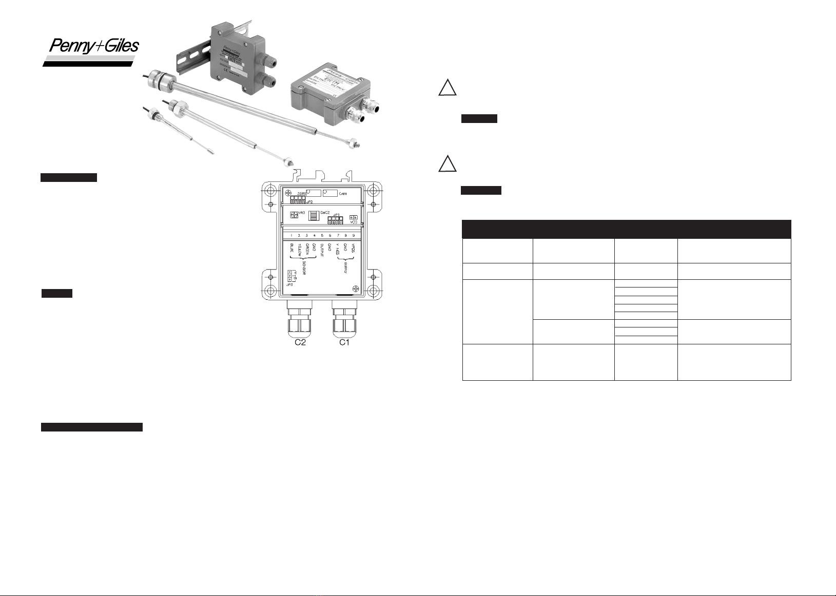
EICT
Montage- und Einstellungsanleitung
BESCHREIBUNG
Die Modelle EICT und EICTM sind spezielle
Signalaufbereitungselektronik-Module für die ICT- und SLT-
Produktpalette kontaktloser linearer Wegaufnehmer von Penny + Giles.
Diese Module enthalten eine Hochleistungsschaltung zum Betrieb des
Wegaufnehmers und liefern eine Vielzahl an Ausgangssignalen,
nachdem der Anwender eine einfache Konfiguration mit Nullpunkts-
und Verstärkungsabgleich durchgeführt hat. Die Elektronik wird in
verschiedenen Gehäusen geliefert, die in Schutzart IP66 (EICT) oder
IP68 (EICTM) abgedichtet sind. Die vollständige Produktspezifikation der
EICT- bzw. EICTM-Module finden Sie in der jeweiligen Wegaufnehmer-
Produktbroschüre.
EINBAU
• Das EICT-Modul kann auf zwei Arten eingebaut werden. Erstens
kann es mit 4 Zylinderschrauben M5 mit mindestens 28 mm Länge
auf einer Schottwand innerhalb 10 m Abstand vom Wegaufnehmer
mit einem empfohlenen Anzugmoment von 4 Nm angeschraubt
werden. Die Befestigungsbohrungen finden Sie nach dem Öffnen
des Gehäusedeckels in den Gehäuseecken. Alternativ ist die
Gehäuserückwand für die Montage auf einer Hutschiene nach DIN EN50022 oder EN50035 gestaltet.
Das EICT-Modul ist in Schutzart IP66 abgedichtet.
• Das EICTM-Modul kann nur auf einer Schottwand, genau wie beim EICT-Modul beschrieben, befestigt
werden. Das EICTM-Modul ist in Schutzart IP68 abgedichtet.
• Der Anwender sollte darauf achten, dass die Gummidichtung im Deckel richtig eingelegt ist, bevor er den
Deckel nach der Konfigurierung wieder aufschraubt. Das empfohlene Anzugmoment für die
Deckelschrauben ist 2 Nm.
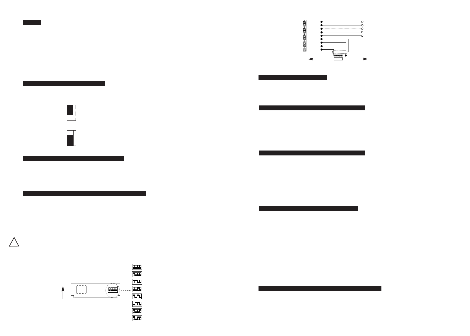
HINWEISE ZUR VERKABELUNG
• Die Module steuern die ICT- oder SLT-Wegaufnehmer nur dann korrekt, wenn eine geeignete
Sensorkalibrierungs-Modulkarte (SCMC) auf die Stiftleiste JP1 gesteckt ist. Dieses SCMC-Längenmodul
wird in der Verpackung des Wegaufnehmers mitgeliefert.
•EICT-Modul – Die Spannungsversorgung für das Modul, die Wegaufnehmer- und Ausgangs-Anschlüsse
werden durch zwei in Schutzart IP66 abgedichtete Kabelverschraubungen geführt, die für
Kabeldurchmesser von 2,5 bis 6 mm geeignet sind
•EICTM modul - Die Spannungsversorgung für das Modul, die Wegaufnehmer- und Ausgangs-Anschlüsse
werden durch zwei in Schutzart IP68 abgedichtete Kabelverschraubungen geführt, die für
Kabeldurchmesser von 3 bis 8 mm geeignet sind.
• Der Anwender sollte darauf achten, dass die Kabelverschraubungen genügend angezogen sind, um sicher
zu stellen, dass die Kabel ordnungsgemäß geklemmt und abgedichtet sind.
• Der Anwender sollte auch auf eine geeignete Abdichtung der entgegengesetzten Anschlüsse der
Spannungsversorgung, des Wegaufnehmers und der Ausgänge achten, damit keine Feuchtigkeit innerhalb
der Kabel in das EICT/EICTM-Modul kriechen kann.
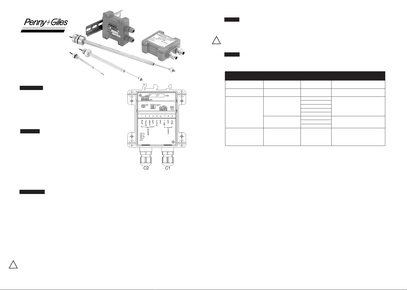
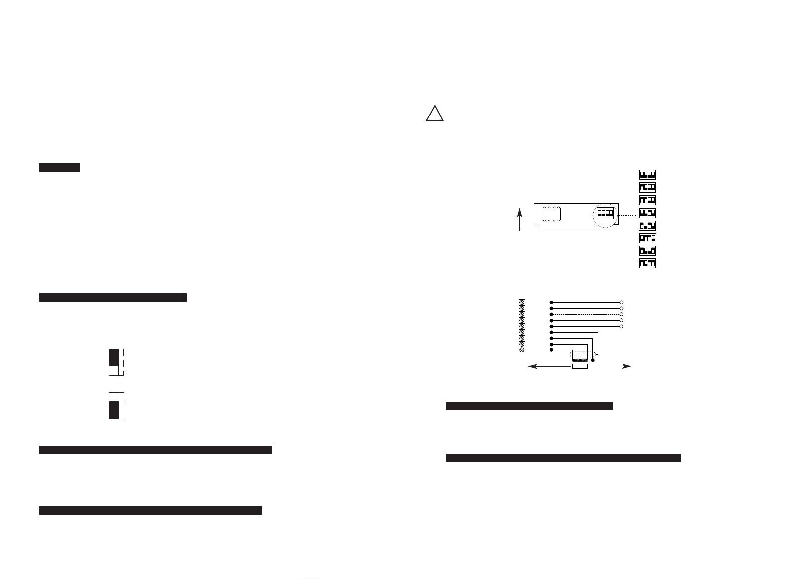
INNOVATION IN MOTION
Fig.1
• Der Kabelanschluss erfolgt über eine Schraubklemmleiste auf der EICT/EICTM- Platine.
• Das Gehäuse ist intern nicht gemasst, weshalb es auf einem Chassis montiert werden kann, das auf
einem Spannungspotential ungleich 0 Vdc liegt.
• Bei Fragen zur Massung wenden Sie sich an Ihren Systemingenieur.
•Wichtig: Die Schritte 1 bis 7 müssen vor dem Anschluss einer Spannungsversorgung an das
EICT/EICTM-Modul durchgeführt werden. Fehlerhafte Verbindungen können das EICT/EICTM beim
Einschalten zerstören!
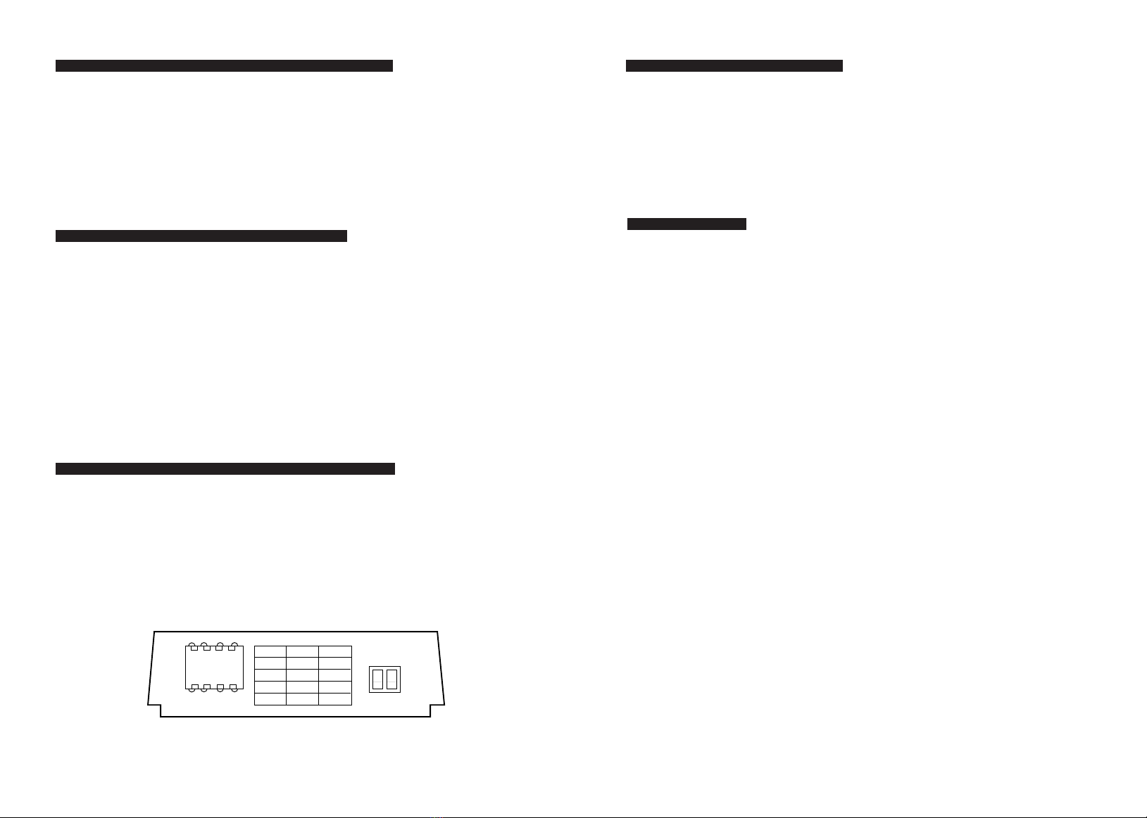
Schritt 1
Zum Entfernen des Gehäusedeckels die vier Schrauben lösen. Die Position der Dichtung im Deckel sollte
festgehalten werden. Die mit dem Wegaufnehmer gelieferte Längenmodulkarte (SCMC) ist in Position JP1
einzusetzen (siehe Abb. 1).
Wichtiger Hinweis: Die Sensorkalibrierungs-Modulkarte (SCMC) darf nach der Kalibrierung nicht
entfernt werden, damit eine einwandfreie Funktion des Sensorsystems gewährleistet ist!
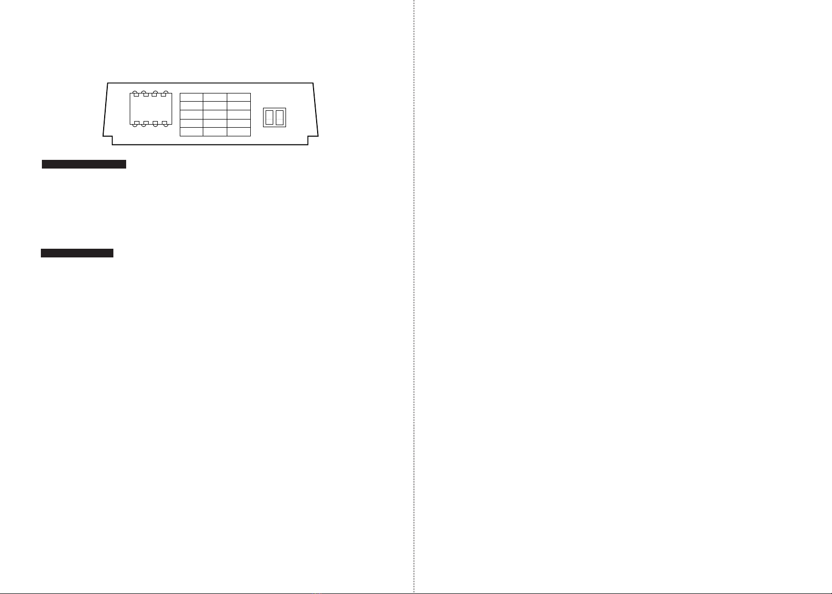
Schritt 2
Bestimmen Sie mit Hilfe der folgenden Optionsmatrix die MAXIMALEN und MINIMALEN
Versorgungsspannungs-Parameter.
CAUTION
!
CAUTION
!
Hinweis A: Duale Versorgungsspannung
• Das EICT/EICTM benötigt - mit oder ohne Optionskarte - nur eine unipolare Versorgungsspannung an den
Klemmen GND und VPOS. Wenn die Optionskarte VM (Spannungsmodul) eingebaut ist, erzeugt ein
interner negativer Rail-Generator 0 V und negative Ausgangsspannungen.
• In manchen Fällen ist eine externe negative Versorgungsspannung im Bereich - 10 bis -30 Vdc verfügbar
(z. B., wenn das EICT eine früheres Signalaufbereitungs-Modell ersetzt). Es ist zulässig, diese Spannung
an VNEG anzuschließen, wodurch der interne negative Rail-Generator auf der EICTVM-Optionskarte
deaktiviert wird und Strom aus der externen Versorgung gezogen wird.
• Um Ausgangssignale von -10 Vdc oder -7,5 Vdc zu erhalten, sollte die externe negative
Versorgungsspannung mindestens -13,5 Vdc betragen.
Hinweis B: Einstellbereich
• Das Zero Potentiometer hat ca. 20 Umdrehungen, entsprechend einem Einstellbereich von -10% bis
+60% des nominellen Sensorbereichs.
• Das Gain Potentiometer hat ca. 20 Umdrehungen, entsprechend einem Einstellbereich von +40% bis
+110% des nominellen Sensorbereichs.
• Der minimale Sensorbereich ist 50% des nominellen Sensorbereichs.
Die Überwurfmuttern C1 und C2 lösen (siehe Abb. 1). Siehe Hinweis [4] hinsichtlich des Kabeldurchmessers.